
Ceramic Quad Flat Package (CQFP): Design, Reliability, Assembly, and When to Use It
13 min
- What Is a Ceramic Quad Flat Package (CQFP)?
- Why CQFP Still Matters in High-Reliability Electronics
- Ceramic Quad Flat Package (CQFP) vs Plastic Quad Flat Package (PQFP): Key Differences Engineers Must Know
- When Should You Choose a CQFP Package?
- How Is a CQFP Package Constructed?
- CQFP Package Sizes, Pin Counts, and Dimensions
- PCB Footprint Design Guidelines for CQFP Package
- How Does a CQFP Package Handle Heat and Thermal Cycling?
- Common Engineering Mistakes When Using CQFP Package
- What Are the Assembly Challenges of CQFP Packages?
- How JLCPCB Handles CQFP Assembly Reliably
- Design for Manufacturing (DFM) Tips for CQFP Assembly
- Conclusion
- FAQ: Ceramic Quad Flat Pack (CQFP)
When system failure is not acceptable, IC package selection becomes a reliability-driven engineering decision rather than a cost-driven one. In such scenarios, the limitations of plastic IC packages quickly emerge under sustained thermal stress, vibration, and harsh environmental exposure.
This is precisely where the Ceramic Quad Flat Package (CQFP) remains a deliberate choice. Unlike plastic QFPs, CQFP packages offer hermetic sealing, superior dimensional stability, and predictable long-term aging—characteristics that are critical in aerospace, space, defense, and other high-reliability electronics.
In this article, we examine what truly differentiates CQFP packaging from its plastic counterparts, including internal construction, material systems, PCB footprint design considerations, assembly challenges, and thermal performance. The goal is to help engineers determine when a CQFP package is necessary—and when it is not—so reliability margins are never left to assumption.
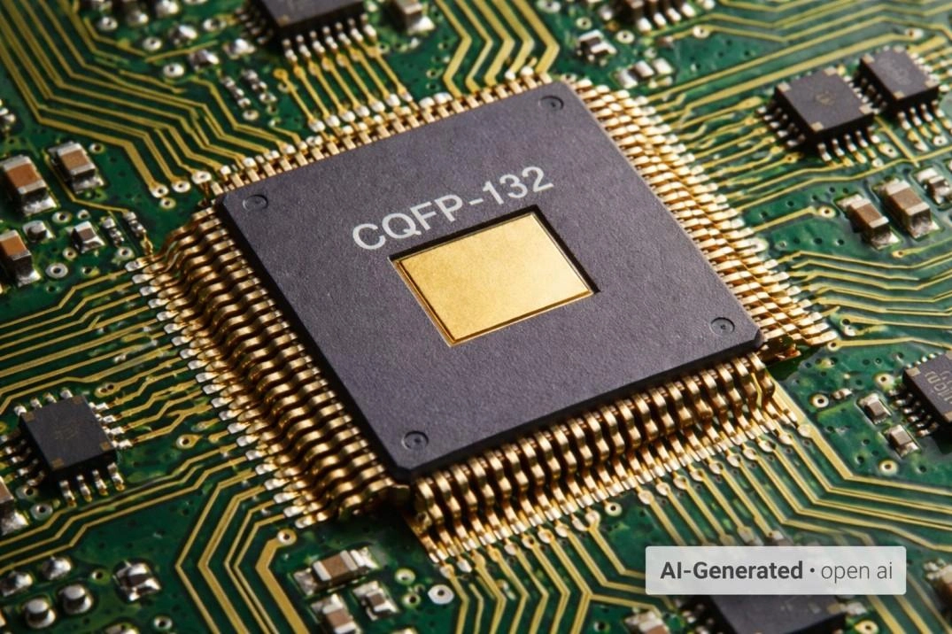
Ceramic Quad Flat Package CQFP-132 IC package
What Is a Ceramic Quad Flat Package (CQFP)?
A Ceramic Quad Flat Package (CQFP) is a surface-mount IC package with a ceramic body and gull-wing leads on all four sides, designed for high-reliability electronics. Unlike plastic QFPs, CQFP packages are hermetically sealed, providing long-term protection against moisture and environmental contamination.
In a CQFP, the silicon die is mounted on a ceramic substrate and enclosed within a sealed cavity using a ceramic or metal lid bonded by glass frit or solder. This construction prevents moisture absorption, package swelling, and material aging commonly seen in plastic packages, especially under high temperature and long service life conditions.
Due to their higher cost and stricter assembly requirements, CQFP packages are not used for manufacturing convenience. They are intentionally selected for aerospace, space, and other mission-critical applications where predictable aging, thermal stability, and decades-long reliability are mandatory.
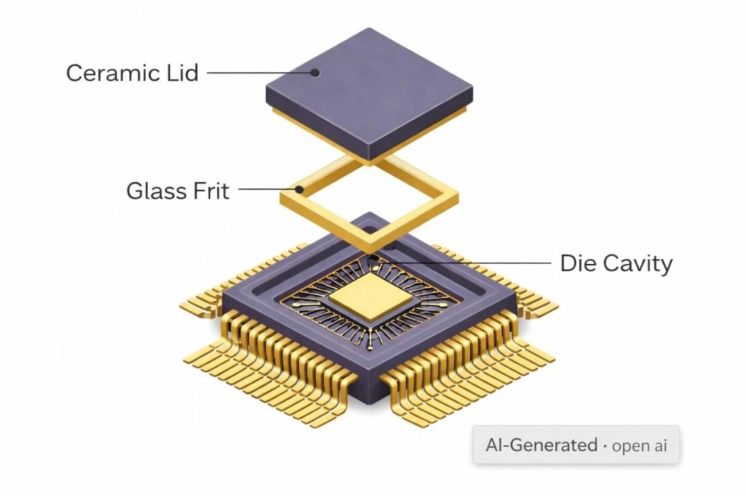
CQFP internal structure
Technical Specifications of CQFP Package
| Property | Typical Value / Material | Industry Standard |
|---|---|---|
| Body Material | High-purity Alumina (90–92%) | Verified per ASTM D116 |
| Seal Type | Hermetic (Glass Frit or AuSn Solder) | MIL-STD-883, Method 1014 |
| Lead Frame | Kovar (Fe-Ni-Co) or Alloy 42 | ASTM F15 |
| CTE (Ceramic) | ~6.5 to 7.0 ppm/℃ | Substrate only, matches silicon |
| Moisture Sensitivity | MSL 1 (Unlimited Floor Life) | J-STD-020 |
Why CQFP Still Matters in High-Reliability Electronics
CQFP packages remain relevant in applications where long-term reliability limits plastic IC packaging. In aerospace and space systems, wide temperature ranges, vibration, and decades-long service life make hermetic sealing and ceramic dimensional stability essential rather than optional.
CQFPs are also deliberately used in industrial and high-temperature environments where sustained heat accelerates moisture ingress, material aging, and mechanical creep in plastic packages. Although CQFPs increase cost and assembly complexity, they are justified when predictable aging and environmental isolation are critical. Where these requirements do not dominate, CQFP is often unnecessary.
Ceramic Quad Flat Package (CQFP) vs Plastic Quad Flat Package (PQFP): Key Differences Engineers Must Know
| Parameter | CQFP (Ceramic QFP) | Plastic QFP (PQFP) |
|---|---|---|
| Body Material | Ceramic substrate with sealed cavity | Epoxy molding compound |
| Moisture Protection | Hermetic, typically MSL 1 | Moisture permeable |
| Thermal Stability | Stable across wide temperature range | Degrades at elevated temperature |
| CTE (ppm/°C) | 6–7 (closer to silicon) | 15–25 (mismatch causes stress) |
| Long-Term Aging | Minimal change over the decades | Noticeable over time |
| Assembly Cost | Higher, due to materials and tighter process control | Lower, optimized for volume |
| Typical Applications | Aerospace, space, high-reliability industrial | Consumer and standard industrial |
Engineers' Takeaway:
CQFPs are deliberately chosen for environments where long-term reliability, hermetic protection, and thermal stability are critical. Plastic QFPs excel in cost-sensitive, high-volume applications, but their epoxy bodies absorb moisture, creep under heat, and transfer stress to wire bonds over time.
Key differentiators for CQFP are:
● Hermetic sealing prevents moisture-related failures
● CTE matching with silicon reduces thermal fatigue
● Stable material properties ensure predictable aging over decades
In short, CQFP is not about cost or ease of assembly—it’s about guaranteed performance where failure is unacceptable.
CQFP construction prioritizes decades-long reliability under thermal, mechanical, and environmental stress, making it the preferred choice for aerospace, space, and high-reliability industrial systems, where plastic packages cannot meet lifetime requirements.
When Should You Choose a CQFP Package?
| Condition | Recommendation |
|---|---|
| Hermetic sealing required | CQFP preferred |
| Long-term thermal stability needed | CQFP preferred |
| Operation in harsh environments (humidity, vibration, high temp) | CQFP preferred |
| Service life of 10–30+ years | CQFP preferred |
| Cost-sensitive, high-volume production | Plastic QFP preferred |
| Simple assembly or benign conditions | Plastic QFP sufficient |
Summary: CQFP packages should be chosen only when reliability, environmental resistance, and long service life outweigh cost and assembly complexity. For standard consumer or industrial applications, plastic QFPs remain more practical.
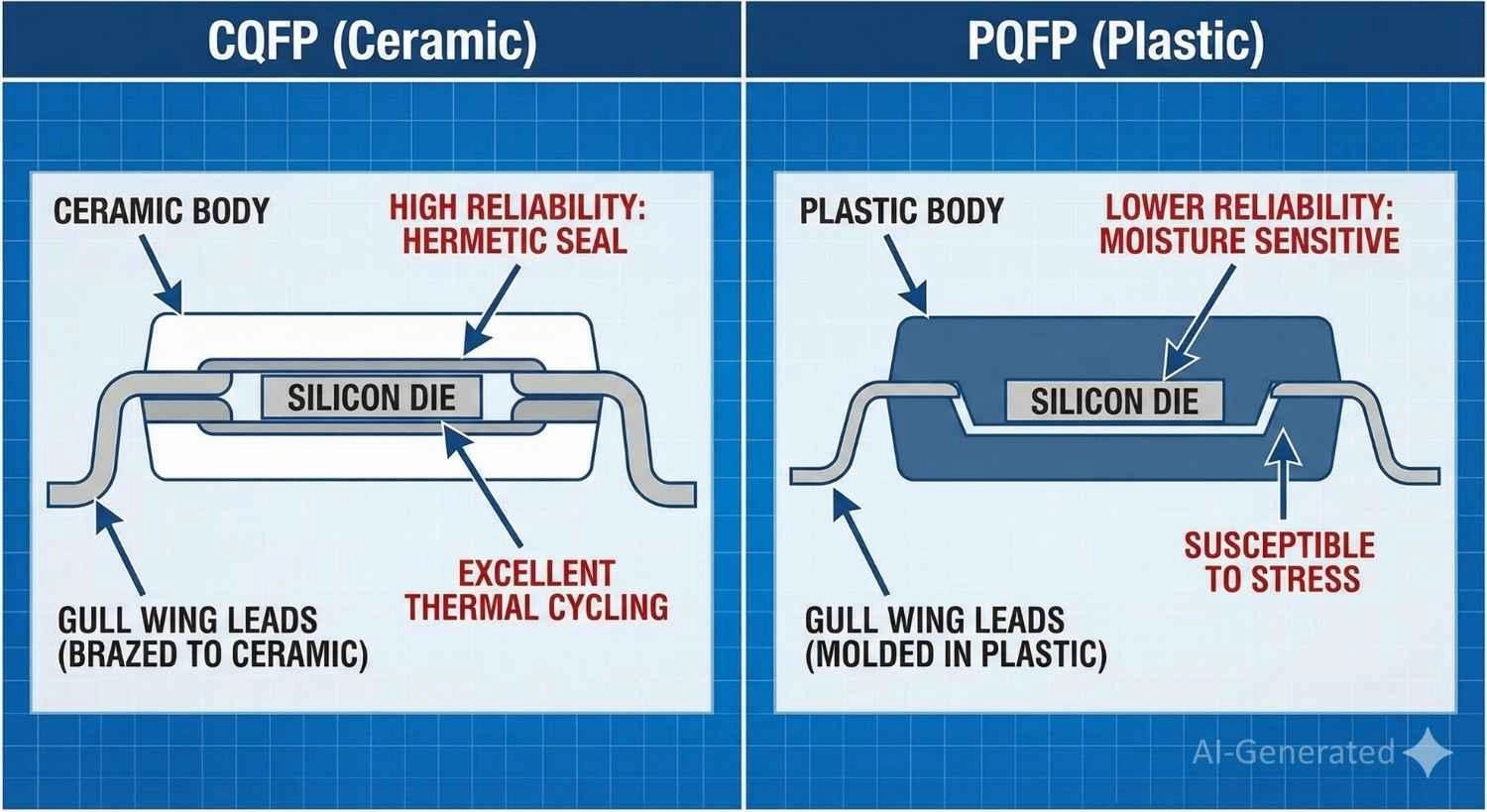
CQFP vs PQFP internal frame, showing the difference between ceramic hermetic sealing and plastic encapsulation
Pro Tip:
CQFP ceramic packages are rigid, expensive, and unforgiving of footprint errors.
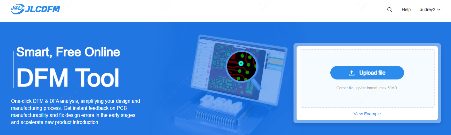
Before releasing the layout, it is strongly recommended to run a DFM check focused on pad geometry, lead pitch clearance, and solder fillet allowances. Catching these issues early helps avoid costly rework or scrap on high-reliability ceramic assemblies.
JLCPCB offers a free online DFM tool that can be utilized during the layout stage to validate these details before fabrication.
How Is a CQFP Package Constructed?
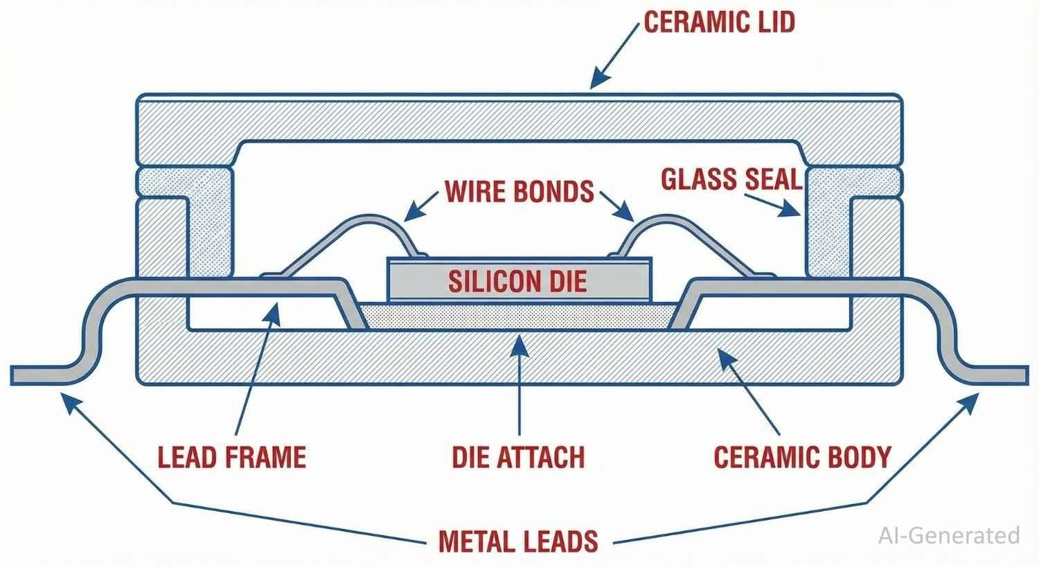
CQFP package structure
The reliability of a CQFP (Ceramic Quad Flat Package) comes directly from its construction and materials. Every component is selected for long-term thermal and mechanical stability, ensuring predictable performance over decades.
1. Ceramic Body and Substrate
At the core is a ceramic substrate, typically high-purity alumina or multilayer ceramic. Ceramics provide dimensional stability, high stiffness, and low thermal expansion, maintaining die, wire, and lead alignment through repeated thermal cycling. Their stable dielectric properties make them ideal for precision analog and mixed-signal designs, while resistance to humidity and contaminants supports long service life.
2. Die Attach and Wire Bonding
The silicon die is bonded directly to the ceramic substrate using gold-based die attach or conductive epoxy. Electrical connections are made with gold wire bonding, chosen for corrosion resistance and proven long-term reliability. The rigid ceramic base minimizes mechanical strain on the bonds, significantly reducing fatigue during thermal cycling compared to plastic QFPs.
3. Hermetic Sealing
A CQFP features a hermetic cavity, sealed with a ceramic or metal lid via glass frit or solder. This isolation prevents moisture ingress, corrosion, and parameter drift, maintaining MSL 1 classification. Hermeticity also ensures compatibility with vacuum environments and provides protection against ionizing radiation, critical for aerospace and space applications.
4. Lead and Metallization
Leads are made from Kovar (Fe-Ni-Co) or copper alloys, chosen for controlled thermal expansion and mechanical durability. Leads are plated for reliable soldering and designed to withstand vibration, shock, and thermal cycling, preserving mechanical integrity over long service life.
CQFP Package Sizes, Pin Counts, and Dimensions
CQFP packages are offered in a limited set of manufacturer-defined outlines, typically tied to aerospace or high-reliability qualification programs rather than open, high-volume standards. Compared with plastic QFPs, available options are fewer, reflecting the constraints of ceramic construction and hermetic sealing.
| Parameter | Engineering-Relevant Characteristics |
|---|---|
| Pin Count | Commonly encountered in mid- to high-pin-count devices (e.g., ~44 to ~200 leads), with exact offerings dependent on vendor and qualification level |
| Lead Pitch | Most CQFPs use 1.27 mm (50 mil) or 0.635 mm (25 mil) pitch; finer pitches exist but are less common and tightly controlled |
| Body Size | Larger than equivalent plastic QFPs due to the ceramic substrate and sealed cavity |
| Package Height | Greater overall height, driven by the ceramic base and hermetic lid |
| Dimensional Tolerance | Tighter lot-to-lot control than mass-market plastic packages, with reduced warpage and mechanical variation |
Because CQFPs are frequently used in aerospace and space-qualified programs, manufacturer datasheets and outline drawings must be treated as authoritative.
Nominal package sizes alone are insufficient for footprint design. Small deviations in lead geometry or body dimensions can significantly affect solder fillet formation and long-term joint reliability in ceramic packages.
PCB Footprint Design Guidelines for CQFP Package
Designing PCB footprints for CQFP packages requires a different mindset than plastic QFPs. Ceramic packages are mechanically rigid and do not absorb strain through package deformation.
As a result, thermal expansion mismatch and mechanical loading are transferred almost entirely into the solder joints. In CQFP assemblies, footprint accuracy is a reliability driver, not just an assembly concern.
Why CQFP Footprints Are More Sensitive
Unlike plastic QFPs, CQFP bodies do not flex during reflow or thermal cycling. Differential expansion between the ceramic package, copper pads, and the PCB laminate concentrates stress at the heel and toe regions of the solder joints. Small errors in pad length, lead alignment, or coplanarity that might be tolerated in plastic packages can accelerate fatigue cracking in CQFP assemblies.
For this reason, CQFP packages show lower tolerance to generic or “reused” QFP land patterns. Designs that initially pass inspection may still develop joint degradation after extended thermal cycling or vibration exposure.
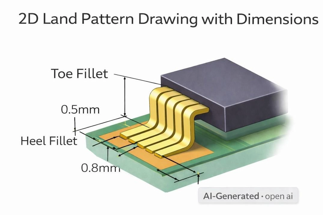
CQFP PCB land pattern design dimensions and solder mask dams
CQFP-Specific Land Pattern and Pad Design Guidelines
● Follow the manufacturer’s recommended land pattern without substitution. For CQFPs, datasheet dimensions override IPC nominal footprints.
● Avoid oversized pads. Excess solder volume increases joint stiffness and raises cyclic stress at the heel of the lead.
● Control pad length to ensure balanced toe and heel fillets. Overextended pads shift the neutral point of the joint and reduce fatigue life.
● Match pad width closely to lead width. This minimizes lateral solder flow and helps maintain lead coplanarity during reflow.
● Use conservative solder mask openings. Well-defined mask dams are critical at finer lead pitches to prevent bridging and uneven fillet formation.
● Verify courtyard and inspection access early. CQFP leads are less forgiving during rework due to ceramic rigidity and lead strength.
Reusing a plastic QFP footprint for a CQFP package is a common root cause of long-term reliability failures. While such designs may assemble successfully, the mechanical behavior of ceramic packages makes these shortcuts risky in high-reliability applications. For CQFP assemblies, footprint correctness is inseparable from product lifetime.
How Does a CQFP Package Handle Heat and Thermal Cycling?
CQFP packages are well suited for environments where high temperature and repeated thermal cycling are normal operating conditions. The ceramic body remains mechanically stable at elevated temperatures and does not creep or soften over time, preventing the gradual package deformation seen in plastic IC packages.
Although thermal expansion still generates stress, the rigidity of ceramic materials prevents stress accumulation through package distortion. This results in more predictable solder joint loading and improved fatigue resistance over long service life.
In addition, ceramic substrates maintain stable thermal conductivity, helping keep junction-to-case thermal behavior consistent throughout extended operation.
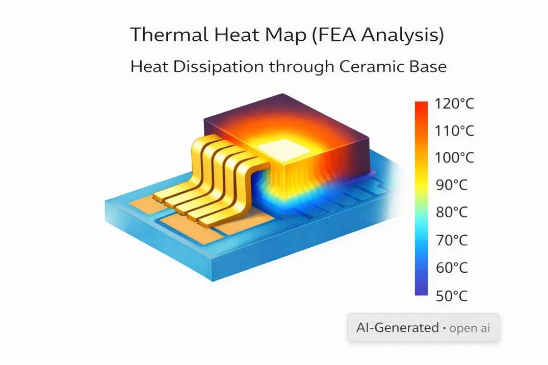
CQFP thermal resistance junction-to-case heat dissipation analysis
Common Engineering Mistakes When Using CQFP Package
Even experienced engineers can encounter reliability issues if CQFP-specific requirements are ignored. Common mistakes include:
1. Reusing plastic QFP footprints – Ignoring ceramic-specific pad geometries leads to solder joint fatigue or bridging.
2. Neglecting CTE mismatch – Failing to account for differential expansion between ceramic and PCB can accelerate joint fatigue.
3. Applying generic reflow profiles – Profiles tuned for plastic packages may overheat or under-reflow ceramic leads.
4. Underestimating assembly complexity and cost – Assuming ceramic behaves like plastic can lead to unexpected failures and increased scrap.
5. Skipping DFM or inspection for ceramic rigidity – Lack of pre-production review can miss subtle design errors that impact long-term reliability.
What Are the Assembly Challenges of CQFP Packages?
CQFP packages behave differently from plastic QFPs due to their rigid ceramic body and hermetic construction. Key assembly constraints include:
● Limited process margin – Ceramic packages cannot flex to absorb placement errors. Minor misalignments show up directly in solder joints.
● Thermal sensitivity during reflow – Rapid local heating can induce stress or cracking; reflow profiles must match the ceramic thermal mass.
● Rework constraints – Localized soldering or hot-air rework carries higher risk of damaging the package or leads.
● Lead coplanarity and solder wetting – Deviations in lead height or pad geometry are less forgiving than with plastic QFPs.
In summary, CQFP assembly demands tighter process control, precise placement, and adherence to recommended thermal profiles. Experience with ceramic packages significantly improves yield and reliability.
How JLCPCB Handles CQFP Assembly Reliably
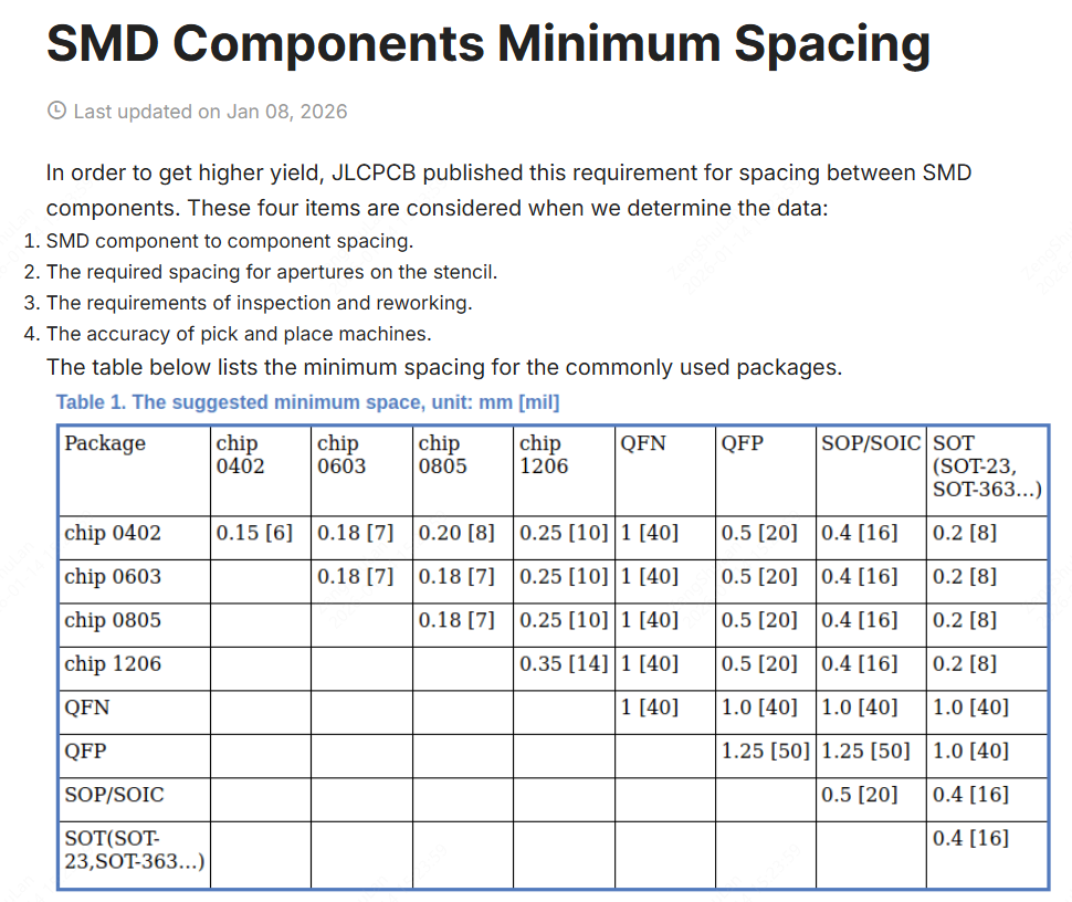
JLCPCB’s SMT assembly process reliably supports CQFP packages with 0.5 mm pin pitch, a common fine-pitch QFP configuration, by adhering to defined minimum spacing standards for surface-mount components.
These spacing rules account for component-to-component clearance, stencil aperture requirements, inspection and rework access, and the placement accuracy of automated pick-and-place machines, ensuring manufacturability for fine-pitch ICs such as CQFP.
By maintaining sufficient spacing and following proven assembly protocols, JLCPCB helps reduce risks like solder bridging and misplacement during reflow, enabling consistent, high-quality results for boards using CQFP and other fine-pitch packages.

Further read: Minimum spacing requirements for SMD components
Design for Manufacturing (DFM) Tips for CQFP Assembly
CQFP packages demand precise DFM planning due to their rigid ceramic body and hermetic construction. Key considerations include:
● Pad geometry & solder mask – Ensure pad lengths and widths support robust toe/heel fillets; maintain mask dams to prevent bridging.
● Lead coplanarity & clearance – Check for uniform lead height and adequate spacing for inspection and rework.
● Reflow profile & thermal mass – Adjust soldering profiles to accommodate ceramic’s slower heat absorption.
● Early DFM verification – Use tools like JLCPCB’s design checks to catch footprint, soldering, or clearance issues before fabrication.
Compliance: Align with MIL-PRF-38535, MIL-STD-883, and NASA-STD-8739.3 to meet high-reliability and aerospace-grade requirements.
Following these tips reduces assembly failures, improves yield, and ensures long-term reliability of CQFP-based systems.
Conclusion
Ceramic Quad Flat Packages (CQFPs) remain the preferred choice for high-reliability electronics where hermetic sealing, thermal stability, and decades-long service life are critical.
While more expensive and demanding in assembly than plastic QFPs, their predictable mechanical, thermal, and environmental behavior ensures long-term performance in aerospace, space, and harsh industrial applications.
Designers should carefully consider footprint, DFM, and thermal management to fully leverage CQFP advantages, ensuring robust, reliable systems over extended operational lifetimes.
FAQ: Ceramic Quad Flat Pack (CQFP)
1. Can a CQFP directly replace a plastic QFP?
No. While CQFP and plastic QFP may appear similar externally, CQFP packages differ in mechanical rigidity, thermal behavior, and assembly requirements. Direct replacement without redesign often causes solder joint fatigue, wire bond stress, and long-term reliability issues in high-reliability electronics such as aerospace or industrial systems.
2. Are CQFP packages moisture sensitive?
No. Most CQFPs are hermetically sealed and rated MSL 1, making them inherently resistant to moisture absorption. Unlike plastic QFPs, they maintain stable electrical and mechanical performance even in humid or high-temperature environments, which is critical for long-term operation in harsh or space-grade applications.
3. Why are CQFP packages more expensive than plastic QFPs?
CQFP costs are higher due to ceramic materials, hermetic sealing processes, tighter dimensional tolerances, and low-volume production. These factors ensure predictable mechanical and thermal performance over decades, which is essential for high-reliability electronics, aerospace, and industrial systems.
4. Do CQFP packages require special PCB footprints?
Yes. CQFP footprints require conservative pad geometry, precise solder mask design, and attention to lead-to-pad alignment. Simply reusing a plastic QFP footprint can result in solder joint cracks or assembly defects. Proper CQFP footprint design is crucial for maintaining long-term reliability and robust performance in high-reliability applications.
Popular Articles
• SMD Diode Code Lookup: Full List, Marking Guide & Identification [2026 Guide]
• SMD Resistor Package Sizes: Complete Size Chart, Footprints & How to Choose
• SMD Capacitor Codes: Identification, Markings, and Polarity
• SMD Capacitor Sizes: Complete Size Chart and Selection Tips for PCB Design and Assembly
• How to Solder SMD Components Like a Pro [2026 Updated]
Keep Learning
Thin Film vs. Thick Film Resistors: Key Differences & Selection Guide
Key Takeaways Default to thick film resistors for most designs. They are cost-effective, robust, and ideal for pull-ups, LED current-limiting, digital circuits, and surge-prone applications. Choose thin-film resistors whenever a resistor defines an analog quantity, such as a voltage divider, reference network, gain-setting circuit, or current-sensing signal chain. Their tight tolerance and low TCR help maintain measurement accuracy over temperature and time. Most PCB designs use thick film or thin fil......
Capacitor Types Explained: Applications, Differences, and Selection Guide
Capacitors are the most widely used parts in electronics design, from input/output coupling to bypassing and decoupling networks; they find applications everywhere. And if you get the wrong part/value placed, the consequences may be you get an audible whine from a supply rail, a bootloader that won't start, or a capacitor that lights up like a match. The question that never comes up is "which brand?" It's always “which type and what value.” This tutorial does not waste time on a textbook explanation o......
PoP Package (Package on Package) Explained: Architecture, Assembly, and SMT Challenges
In the race for miniaturization, fitting more processing power into smaller footprints is the ultimate challenge for PCB designers. Package on Package (PoP) technology answers this by integrating logic and memory vertically, becoming the standard for modern mobile processors. However, this 3D architecture demands advanced SMT assembly capabilities beyond standard fabrication. JLCPCB specializes in the high-precision manufacturing required to master these complex stacks. This guide covers how PoP packa......
What Is a PQFP Package? Plastic Quad Flat Package Design, Footprint, and Assembly Guide
The Plastic Quad Flat Package (PQFP) is a widely used IC package in industrial, automotive, and embedded designs. This article provides a practical, engineering-focused guide to PQFP package. It explains how PQFP is built, when it makes sense to use it, how it compares with newer package types, and what designers should consider in terms of footprint design, thermal performance, signal integrity, manufacturing, and reliability. What Is a PQFP Package (Plastic Quad Flat Package)? A Plastic Quad Flat Pa......
Small Outline Integrated Circuit (SOIC): Package, Specs & Uses
As designs transition from legacy through-hole components to high-density Surface Mount Technology (SMT), the Small Outline Integrated Circuit (SOIC) remains the industry standard for operational amplifiers, flash memory, sensors, and microcontrollers. It stands as a testament to balanced engineering, offering a perfect compromise between the miniaturisation demanded by modern consumer electronics and the ruggedness required for industrial applications. This article serves as a definitive engineering ......
A Complete Guide to Surface Mount Device (SMD)
Imagine holding a smartphone in your hand. Inside that sleek device lies a complex network of thousands of miniature components — resistors smaller than a grain of rice, capacitors thinner than a fingernail, and integrated circuits containing millions of transistors. Without Surface Mount Technology (SMT) and its compact Surface Mount Devices (SMDs), none of this would exist. Just a few decades ago, electronics were bulky. Radios filled desks, computers filled rooms, and assembling a circuit meant dri......