
ZIF Connectors Simplify Flexible PCB Assembly with Tool-Free Reliability
13 min
- The Growing Need for ZIF Connectors in Flexible PCB Designs
- Main Types of ZIF Connectors and Their PCB Applications
- Design Best Practices for Reliable ZIF Integration
- Manufacturing Considerations for ZIF Connector PCBs
- JLCPCB's Expertise in ZIF Connector PCB Production
- Frequently Asked Questions (FAQ)
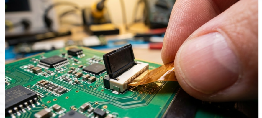
Did you ever attempt to mate a fragile flex cable into a connector and experience that unpleasant resistance, and wonder whether you were tearing off the tail or breaking the casing? It is precisely that tension that the ZIF connectors were supposed to help remove. Zero insertion force technology allows you to slide a flexible printed circuit or flat flexible cable into the receptacle to be mated with, using almost no push force at all, but rather allows a mechanical actuator to hold the cable firmly in position. The ZIF connector has become unavoidable in a market that is characterized by thinner devices, smaller board spaces, and increased assembly lines.
Reliable flex-to-rigid interconnections are needed in smartphones, laptops, wearables, medical instruments, and automotive displays, and they must be able to withstand production handling and thermal cycling. Misaligning this interface will result in intermittent contacts, signal dropouts, and rework that is expensive. In the present day, we will explore all the features of ZIF connector technology, starting with the fundamental operation of the process and connector types, all the way up to footprint design guidelines, manufacturing, and quality control. If you are choosing your first ZIF part number, or you are trying to optimize a high-density flex design, this guide will provide you with the experience to get it just right.
The Growing Need for ZIF Connectors in Flexible PCB Designs
Flexible and rigid-flex PCBs are no longer a niche product. They are found in almost all small consumer devices, and one of the most susceptible interfaces in the whole assembly is the connection point between a flex tail and a rigid motherboard. The requirements of the mating connector have never been greater than they are now, when pitch sizes are reduced to less than 0.5 mm, Band signal speeds are in the gigabit range.
Mechanical stress on the flex tail is induced on the flex tail each time the traditional press-fitting or friction-insertion connectors mate. That stress damages contact pads, raises coverlay edges, and causes micro-cracks in the copper traces at the connector area through repeated assembly and rework operations. All these issues are solved at the source by the ZIF technology.
What Is a ZIF Connector and How Does It Work?
A zero insertion force (ZIF) connector is a two-component connector where the flex circuit or flat cable is pushed into the connector housing virtually without resistance. The connection is not electric when it is inserted. In its place, a mechanical actuator, usually a lever of the flip-type or a sliding clamp, is inserted once the cable has been placed, forcing the cable contacts to press the connector terminals.
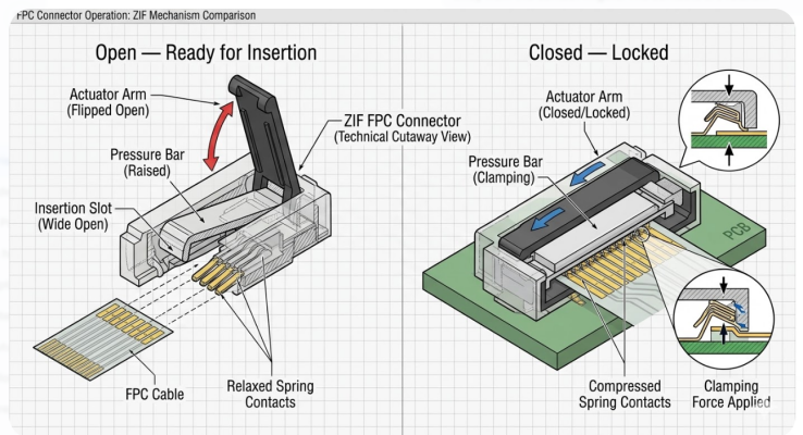
The order is simple. The operator opens the actuator, inserts the FPC or FFC until it clips the internal stop, and closes the actuator. The closing of the actuator pushes a cam or pressure bar, pushing the cable contacts into the connector terminals at a regulated and constant clamping force. This force is spread uniformly throughout all the positions, and contact resistance is maintained consistently across all the pins.
Why Tool-Free Insertion Matters in Modern Flexible Applications
Among the most viable benefits of ZIF connectors, it is possible to note that they do not have to be assembled or reworked with a special tool. Within seconds, an operator can open the actuator using a fingertip or a simple plastic spudger and insert the cable and lock it in place. This is more important than it may seem. When production is of high volume, the cost per unit is directly proportional to assembly speed. A ZIF connection can be achieved in less than 3 seconds as opposed to the time-consuming alignment and controlled force needed to make friction-fit connections.
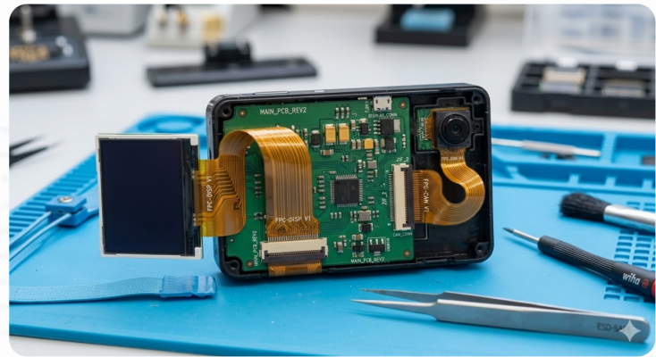
In rework, the cable may be released and reinserted without risking damage to the connector or the flex tail, which is important in yield recovery on costly assemblies. In handheld and small-sized devices, including laptops, tablets, cameras, and health wearables, flex cable disconnection and connection capabilities should be able to be disconnected and reconnected during service and repair to increase the product life. Communities involved in consumer electronics repair are aware of ZIF connectors when they see them, since they are meant to be handled in this manner, tool-free and repeatedly. What has come out is a connector technology that is as effective in the field service bench as it is on the factory floor.
Main Types of ZIF Connectors and Their PCB Applications
Standard ZIF vs. Locking ZIF Designs
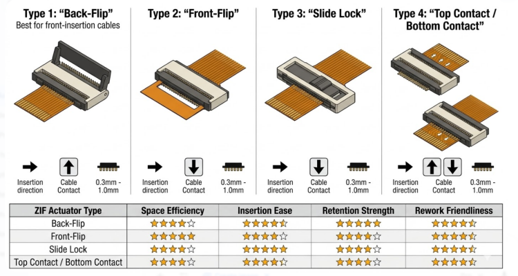
ZIF connectors are available in several actuator configurations, each optimized for different board layouts and cable routing scenarios.
| Actuator Style | Description | Best For |
| Front Flip | Actuator rotates forward, away from the PCB edge; cable inserts from the front | Top-entry designs with vertical cable routing |
| Back Flip | Actuator rotates toward the PCB edge; cable inserts from the opposite side | Low-profile assemblies where the cable routes under the connector |
| Slider | A sliding cover clamps the cable from above | High-vibration environments needing strong retention |
| One-Touch | Push-in latch engages automatically on cable insertion | High-speed assembly lines requiring minimal operator steps |
The most used designs in consumer electronics are front flip and back flip designs. The slider type has better retention force, hence it is a good option when it comes to automotive dashboards and industrial controllers, and any other device that may experience constant vibration. One-touch versions simplify the manufacturing process, but can have a reduced retention force than slider mechanisms.
FPC/FFC Compatibility and Pitch Options
Selecting a ZIF connector starts with matching its specifications to your cable and circuit requirements. The key selection parameters are pitch, position count, contact orientation, and cable thickness.
| Parameter | Common Options |
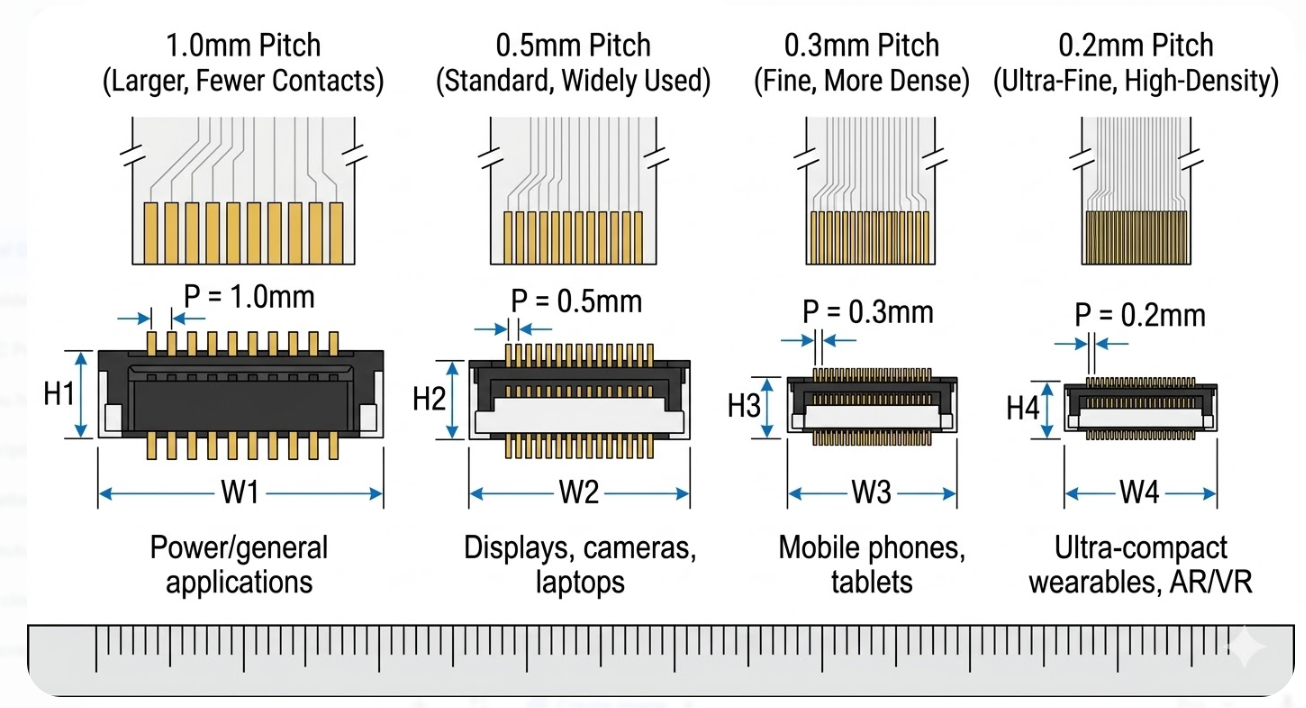
| Pitch | 0.2 mm, 0.225 mm, 0.3 mm, 0.5 mm, 1.0 mm, 1.25 mm |
| Position Count | 4 to 80+ positions |
| Contact Orientation | Top contact, bottom contact, dual contact (both sides) |
| Cable Thickness at Mating Zone | 0.2 mm or 0.3 mm |
| Current Rating (per contact) | 0.3 A to 0.5 A typical |
| Voltage Rating | 50 VAC/DC typical |
| Operating Temperature | -40 C to +105 C |
The 0.5 mm pitch is the workhorse of the industry, covering the vast majority of consumer, industrial, and medical applications.
Design Best Practices for Reliable ZIF Integration
Footprint Layout and Mechanical Reinforcement
Always start with the manufacturer's recommended land pattern. Verify the footprint against the connector datasheet, paying close attention to these items:
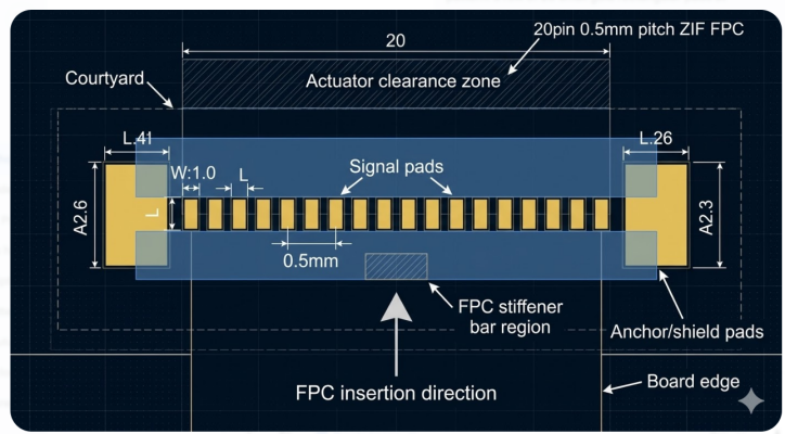
1.Pad geometry and pitch accuracy: even a 0.05 mm error in pad pitch across a 60-position connector accumulates into a significant alignment problem at the far end.
2.Keep-out zones: define keep-out areas around the actuator swing path. A front-flip actuator needs clearance above and in front of the connector body.
3.Insertion direction: Ensure no adjacent tall components block the cable insertion path. The FPC or FFC must slide in straight without deflection.
4.Pick-and-place allowances: SMT placement machines grip the connector body, so confirm that the component has a flat, accessible surface for the vacuum nozzle pickup.
5.Mechanical anchor pads: most ZIF connectors have solder tabs or through-hole anchors on the sides. These carry the mechanical load of cable insertion and actuator operation, so ensure they are properly sized and connected to copper.
For the flex tail itself, a polyimide stiffener is almost always required at the ZIF mating zone. The stiffener must produce a final tail thickness that matches the connector specification.
Creepage, Clearance, and Signal Integrity Rules
Look at the connector datasheet before laying traces to a ZIF connector: check rated voltage, current per contact, and minimum recommended spacing between adjacent pins. Under normal 0.5 mm pitch ZIF rated at 50 VAC, the pin-to-pin gap is naturally constrained by the pitch itself, and therefore, the connector manufacturer has already tested the connector to confirm that the gap would be acceptable under the rated voltage at the specified pollution degree. The general clearance guidelines are presented by IPC-2221.
For high-speed FFC and FPC applications, signal integrity becomes a primary concern. Consider these guidelines:
- Interfaces, including LVDS, MIPI or USB, should use controlled-impedance cables (usually 90 impedance or 100 impedance differential).
- The route differentiates in a symmetric fashion from the connector pads to reduce skew.
- Make FFC as short as practicable. The attenuation of signals with cable length and the crosstalk and EMI pickup are more prone to longer cables.
- In cases where EMI is an issue, use a shielded FFC with ground foil laminated on the cable, and make the shield attached to the board ground by having special ground pins on the connector.
- Make sure that the connector has a connector loss and return loss that matches your channel budget at the desired data rate.
Manufacturing Considerations for ZIF Connector PCBs
Precise Gold Finger Plating and Alignment
The electrical interface is the contact fingers on the flex tail, and the quality of the surface determines the contact resistance and reliability in the long term directly. The most common finish on ZIF contact areas is the electroless nickel immersion gold (ENIG), which offers a flat, corrosion-free finish that is the best conductor. To obtain a longer mating life, electrolytic nickel-gold with a heavier gold layer of 0.5 um up to 1.0 um can be requested.
The presence of any contamination, oxidation, or residual solder paste on the contact fingers will enhance contact resistance, leading to intermittent connections. Protection of the contact area during assembly can be provided by removable masking or process sequencing to ensure that the area remains clean until the final cable insertion.
Assembly Compatibility and Quality Assurance
During SMT assembly, the ZIF connector is placed and reflow-soldered like any other surface-mount component. However, post-reflow inspection must verify several ZIF-specific items:
- Actuator state -- the actuator must be in the fully open position after reflow and before cable insertion. A partially closed actuator can prevent proper cable seating.
- Insertion depth -- after cable insertion, verify that the cable is fully seated against the internal stop. Under-insertion is one of the most common ZIF assembly defects.
- Cable skew -- the cable must be centered and parallel to the connector body. Even slight angular misalignment can cause open contacts on one side.
JLCPCB's Expertise in ZIF Connector PCB Production
Advanced Fabrication for High-Precision ZIF Interfaces
The fabrication process at JLCPCB fully satisfies the fine geometry requirements of ZIF connector landing patterns - the accuracy of the pitch down to 0.5 mm and below, ENIG surface finish with controlled gold thickness allowing reliable contact mating, and laser-cut flex profiles with edge tolerances making ZIF insertion zones error-free. These do not consist of generic hype statements; they are the individual process controls that literally determine whether a ZIF connection will be or will not be a reliable working component, or will become a field failure.
In those impedance-controlled designs, the online impedance calculator of JLCPCB is a life-saving tool--you will be able to enter the desired impedance of a differential pair of routing between those ZIF connector pads. Then the fake stack-up gives the electrical performance that your high-speed FFC interface requires. It particularly comes in handy with LVDS, MIPI, and USB connections that go through ZIF interfaces.
DFM Support and Scalable Manufacturing Solutions
JLCPCB's DFM review checks for common ZIF-related design issues before your boards go into production. Key DFM checkpoints include:
- Connector pad-to-edge clearance and panelization compatibility
- Solder mask opening accuracy around fine-pitch ZIF pads
- Mechanical anchor pad sizing and copper connection
- Flex-tail mating region dimensional compliance with the target connector specification
- Stiffener overlap and thickness buildup verification for the ZIF insertion zone
This upfront review catches problems that would otherwise surface as assembly defects or field failures. Combined with JLCPCB's fast turnaround, starting from $2 for standard PCBs and with 1-2 day production options, you can iterate quickly from prototype to production without sacrificing the precision that ZIF connectors demand.
Proven Reliability for Flexible and Hybrid Boards
Therefore, it is the flex and rigid-flex operations of JLCPCB that are verified against the dimensional and surface specifications in the connector datasheets of the large corporations like Hirose, Molex, Wurth Elektronik, and Amphenol. The fab controls such as the plating of the gold finger, tolerance of the edges, the cleanliness of the surfaces are directly attributed to the connector mating specifications and not some arbitrary internal numbers.
When you are a grad student or an engineer assembling a hybrid rigid-flex using ZIF, the JLCPCB SMT assembly has the capability to follow the entire process, including bare board assembly, connector assembly, reflow, and AOI inspection to ensure the small-pitch ZIF components solder properly. This combined process eliminates the additional handling that always disturbs the parts and ensures the final assembly meets the IPC-A-610 Class 2 or Class 3 requirements, based on the requirements of your product.
Frequently Asked Questions (FAQ)
Q: What is the difference between a ZIF connector and an LIF connector?
A ZIF (Zero Insertion Force) connector uses a mechanical actuator to clamp the cable after it is inserted with no force. A LIF (Low Insertion Force) connector uses spring-loaded terminals that grip the cable through friction during insertion, with no actuator involved. ZIF offers more mating cycles (typically 20-30 vs. 10 for LIF), better cable protection, and more consistent contact force, while LIF is smaller, simpler, and less expensive.
Q: How do I select the correct pitch for my ZIF connector?
Pitch selection depends on your signal density, current requirements, and board space. The 0.5 mm pitch is the most widely used and offers the best balance of density, current capacity (up to 0.5 A per pin), and manufacturing tolerance margin. Use 0.3 mm or 0.2 mm pitch only when board space forces it, and be prepared for tighter layout and fabrication tolerances.
Q: What happens if the FPC cable thickness does not match the ZIF connector specification?
A thickness mismatch will cause either incomplete insertion (cable too thick) or insufficient contact pressure (cable too thin), both leading to unreliable connections. The solution is to use a polyimide stiffener bonded to the flex tail, machined to achieve the target thickness of 0.2 mm or 0.3 mm with a tolerance of plus or minus 0.03 mm.
Q: Which locking style should I choose: front flip, back flip, or slider?
Front flip is the most common choice for general-purpose applications because it provides easy visual confirmation that the actuator is open or closed. Back flip works well when the cable needs to route flat against the PCB surface or exit from the rear. Slider types offer the highest retention force and are preferred for automotive, industrial, and other high-vibration environments.
Q: Are ZIF connectors suitable for high-speed signal applications?
Yes, but with careful design. For interfaces like LVDS, MIPI, or USB operating at gigabit data rates, you need controlled-impedance FFC or FPC cables (typically 90 ohm or 100 ohm differential), symmetric differential pair routing to the connector pads, and shielded cables where EMI is a concern.
Popular Articles
Keep Learning
Creating Clear and Professional Reference Designators for Better PCB Assembly
Key Takeaways Reference designators are essential for accurate PCB assembly, debugging, and maintenance. Use minimum 0.8 mm text height and 0.15 mm line width for clear silkscreen printing. Keep designators on solder mask with proper clearance from pads and vias. Maintain consistent font, size, and orientation across the board. For high-density designs, use an assembly drawing instead of crowded silkscreen. Always run DFM checks to avoid overlapping or missing labels. Ever wonder about the little labe......
How to Design a PCB with Flux.ai (Step-by-Step Guide)
Key Takeaways This step-by-step Flux PCB design tutorial demonstrates the complete workflow by creating a compact 15 × 15 mm USB 2.0 hub, refining the layout, routing high-speed differential traces, and preparing manufacturing files for JLCPCB PCB fabrication and assembly. We are all hearing news; new AI models are being released every month. And it has finally reached the schematic editor. Flux.ai is a browser-based AI PCB design tool with a built-in AI agent that behaves like a junior hardware engin......
How to Design Your Own Keyboard PCB: From Layout to Firmware
Designing a custom keyboard PCB is one of the most rewarding entry points into practical electronics. You not only get a really useful product on your desk, but also you learn schematic capture, matrix scanning, footprint selection, USB, and firmware. Most of the hardware engineers use the same skills that show up on professional boards. This guide walks the entire build from choosing switches, wiring the diode matrix, adding the microcontroller and USB-C, laying out the board, and flashing QMK or VIA......
Don't Let Design Errors Ruin Your Hardware: The Complete Guide to PCB Design Verification
Key Takeaways PCB design verification is the systematic process of validating layouts against electrical, signal integrity, and manufacturing rules before production, preventing costly board respins and launch delays. Schematic verification through Electrical Rules Check (ERC) catches floating inputs, power shorts, and footprint mismatches before layout begins. Design Rule Checking (DRC) ensures trace widths, clearances, and via sizes comply with your fabricator's manufacturing tolerances, especially ......
How to Determine the Right PCB Voltage Clearance for Safe and Reliable Designs
Key Takeaways Clearance is the air gap; Creepage is the surface path — both essential for high-voltage safety. Base spacing on peak voltage and follow IPC-2221 / IEC 60664-1 standards. Major factors: voltage, pollution degree, CTI, altitude, and conductor location. Use isolation slots, guard rings, and conformal coating to optimize spacing. Always run clearance calculations, DFM checks, and Hipot testing before production. Why do two copper traces that work fine at 5V suddenly arc over and burn at 400......
Mastering PCB Footprints: Design Best Practices for Reliable Manufacturing
Key Takeaways A PCB footprint (land pattern) translates component datasheet dimensions into copper pads, solder mask openings, paste apertures, silkscreen, and clearance areas that enable reliable soldering and assembly. Follow IPC-7351 standards and manufacturer DFM rules for pad dimensions, spacing, and layer design to minimize defects like solder bridging, tombstoning, and cracked joints. Choose between through-hole (THT) and surface mount (SMT) footprints based on electrical needs, thermal perform......