
Simultaneous Dual-Frequency Induction Power: When One Frequency Forces the Wrong Compromise
10 min
- Why Two Frequencies Can Be Better Than One
- What "Simultaneous" Means Electrically
- How to Structure Development: Give Each Frequency a Role
- Validation Table: What Success Looks Like
- Electrical Integration: What Gets Harder (and How to Make It Manageable)
- When Sequential Multi-Frequency Is the Better Answer
- A Practical Commissioning Checklist
- Recipe Engineering: Treat Power Split as a First-Class Parameter
- Quality Signals That Prove Dual-Frequency Value
- Integration with Monitoring and QA
- Where Dual-Frequency Often Helps Most
- A Practical Decision Rule
- Designing the Combining Network: Keep Interactions Predictable
- Measurement Strategy: Avoiding Control Ambiguity
- Process Development: What to Record
- Operator Guidance: Keep Adjustments Intentional
- Failure Modes to Plan For
- Practical Documentation: Keep the System Transferable
- A Simple Training Message That Helps
- A Specific Use Case: Gear Hardening as the Classic Dual-Frequency Problem
- Dual-Inverter Architectures: Inductive vs. Capacitive Coupling Paths
- How to Present Dual-Frequency to Stakeholders
- Acceptance Testing: Prove Both Performance and Robustness
- A Note on Maintenance and Spare Strategy
- FAQ about Simultaneous Dual-Frequency Induction Heating
Key Takeaways
Dual-frequency is justified by robustness, not complexity: It should only be adopted when a single frequency forces an unacceptable compromise between surface and bulk heating requirements.
Give each frequency a defined role: Assign the lower frequency to bulk heating/penetration and the higher frequency to surface shaping—then develop recipes one variable at a time.
The combining network is the engineering center of gravity: Frequency-selective coupling paths, thermal rating for worst-case circulating currents, and validated measurement separation are what make dual-frequency reliable.
Treat power split as a first-class parameter: Log split setpoints alongside part outcomes, define operator-adjustable bounds, and prove robustness under realistic disturbances during commissioning.
Why Two Frequencies Can Be Better Than One
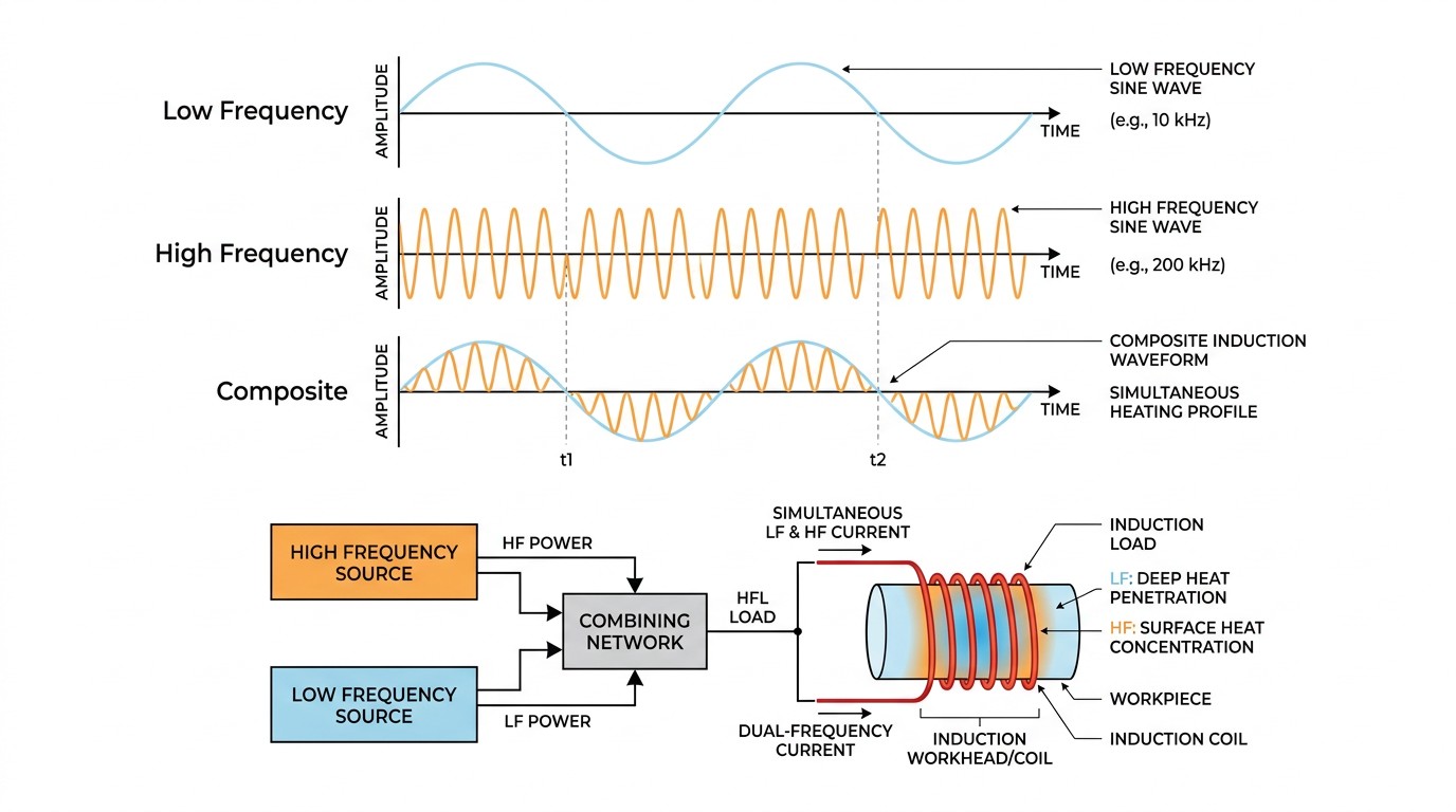
Dual-frequency concept: two components superimpose in the load, creating a composite heating effect.
Frequency shapes where current flows in the workpiece. Lower frequency generally supports deeper penetration; higher frequency concentrates heating nearer surfaces and small features. If your process needs both behaviors simultaneously—not sequentially—dual-frequency can widen the process window.
Examples include applications where surface overheating must be avoided while raising core temperature rapidly, or where material property transitions change coupling and make single-frequency control unstable.
What "Simultaneous" Means Electrically
Simultaneous dual-frequency is not recipe switching. The coil/load sees the superposition of two power components, which changes how matching, sensing, and protection must be designed.
The combining network must prevent one source from back-driving the other, and the matching network must behave acceptably in both frequency bands. Measurement circuits must distinguish components without creating control ambiguity.
How to Structure Development: Give Each Frequency a Role
Teams new to dual-frequency often tune both channels at once and learn nothing. A more reliable approach assigns roles:
- The lower-frequency channel provides bulk heating and penetration.
- The higher-frequency channel shapes surface condition and local gradients.
Then recipe development becomes structured: set LF power to meet core requirements, then add HF power to correct surface behavior.
Validation Table: What Success Looks Like
| Validation Goal | Evidence You Should Collect |
|---|---|
| Wider process window | Lower scrap under coupling/part variation |
| Better gradient control | Measurable reduction in surface-to-core spread |
| Higher productivity | Same quality at shorter cycle time |
| Higher robustness | Fewer trips and less "frequency hunting" |
Electrical Integration: What Gets Harder (and How to Make It Manageable)
Dual-frequency adds integration complexity in predictable areas: combining networks, sensing, and protection. The combining network must keep the two power sources from interacting destructively. Measurement must separate components so control loops do not "fight." Protection must account for composite peaks, not just single-frequency RMS behavior.
The way to make it manageable is to treat dual-frequency as a system from day one. Define measurable success criteria, instrument the right variables, and document the intended tuning process.
When Sequential Multi-Frequency Is the Better Answer
Not every "two behaviors" problem requires simultaneous dual-frequency. In many cases, staged heating (LF then HF) can achieve the same result with less complexity, especially if cycle time allows or if the coil line naturally provides zones.
Simultaneous dual-frequency is most justified when physics demands both effects at once—when delaying one component creates defects or reduces throughput unacceptably.
A Practical Commissioning Checklist
Before production qualification, validate: independent operation of each channel, combining network thermal behavior, measurement separation, and stability under coupling variation. If these are not proven, dual-frequency becomes a black box that only one expert can run.
Recipe Engineering: Treat Power Split as a First-Class Parameter
Once a system can deliver two frequencies simultaneously, the power split becomes a new actuator. That actuator should be treated with the same discipline as any other recipe-critical parameter. Define bounds, define how operators are allowed to adjust it, and define what quality metric it is meant to control.
In practice, teams often find that only a narrow band of splits provides stable improvement. Outside that band, the system may produce unpredictable gradients or create stress in the matching network. That is why split sweeps, recorded against part outcomes, are essential during development.
Quality Signals That Prove Dual-Frequency Value
Dual-frequency is sometimes justified with qualitative language ("more control"). Make it quantitative. Track surface-to-core gradients, cycle time, energy per part, and robustness under deliberate coupling offsets. If those metrics do not improve, the added complexity is not paying for itself.
Integration with Monitoring and QA
Because dual-frequency systems have more degrees of freedom, QA should include additional checks: correct channel enable status, correct split setpoint, and stable detuning indicators in both bands. If you do not log these, troubleshooting becomes guesswork.
Where Dual-Frequency Often Helps Most
Dual-frequency tends to shine where geometry and metallurgy fight each other: edges that overheat while cores lag, or regions where magnetic transitions create abrupt coupling changes. In these cases, simultaneous control can widen the window enough to stabilize production.
A Practical Decision Rule
When to Choose Dual-Frequency
If your single-frequency process can meet quality with acceptable robustness after improving coil design, matching range, and mechanical repeatability, keep it single frequency. If you still see an unavoidable trade-off between surface condition and bulk condition, and controlled trials show dual-frequency widens the window, then the added complexity is justified.
Designing the Combining Network: Keep Interactions Predictable
A dual-frequency system is only as robust as its combining network. The combining network must prevent one channel from seeing the other as a load, and it must do so while maintaining reasonable losses and thermal behavior. In practice, this often means frequency-selective paths, careful impedance isolation, and physical layout designed to keep parasitics from coupling the channels.
Because parasitics matter, combining networks should be validated as built, not only as drawn. High-frequency currents and voltages will find unintended paths if layout is careless.
Measurement Strategy: Avoiding Control Ambiguity
If sensors cannot distinguish the two frequency components, control loops can fight. A robust system uses measurement paths and filtering designed for the specific bands. During commissioning, validate measurement separation by running each channel independently at reduced power and confirming signals behave as expected.
Process Development: What to Record
During recipe development, record not only the split setpoint, but also the resulting kW/kVA signatures, detuning indicators, and part outcome metrics. Dual-frequency projects fail when teams cannot correlate split changes to measurable quality changes.
When you treat split as a controlled variable with logged evidence, dual-frequency becomes an engineering tool rather than a black art.
Operator Guidance: Keep Adjustments Intentional
To keep dual-frequency stable in production, define which setpoints operators may change (often total power within a bounded split) and which require engineering approval. This prevents accidental process changes and keeps the benefits of dual-frequency repeatable shift to shift.
Failure Modes to Plan For
Common Failure Modes in Dual-Frequency Systems
- Thermal failure: The combining network or capacitor elements run hotter than expected because circulating currents are higher under certain splits.
- Measurement failure: Sensors and filters blur the two components, creating unstable control action.
- Procedural failure: Operators adjust split without understanding the role of each channel, creating hidden process changes.
Mitigation Steps
Rate the combining network for worst-case circulating current, not just average kW. Validate measurement separation during commissioning. Document split limits and provide operator-facing guidance that makes correct adjustments easy.
When these steps are taken, dual-frequency systems can run reliably. When they are skipped, the system becomes "expert-only," and the business case collapses.
Practical Documentation: Keep the System Transferable
Dual-frequency projects often succeed technically but fail organizationally when knowledge is not documented. Capture the validated split ranges, the signatures that indicate healthy operation, and the troubleshooting steps that map alarms to physical causes. This is how the capability survives team turnover.
A Simple Training Message That Helps
Operator Training Tip
Explain dual-frequency to operators in one sentence: one channel heats deep, the other shapes the surface. If adjustments are needed, adjust total power first, then adjust split within the validated band. This keeps the process consistent and prevents unbounded tuning.
A Specific Use Case: Gear Hardening as the Classic Dual-Frequency Problem

Dual-frequency hardware concepts.
The source calls out gear hardening as an obvious application for simultaneous dual-frequency heating. The physics is intuitive: a relatively low frequency can drive heat toward the root region of the tooth, while a higher frequency concentrates heating at the surface and tip. If you attempt to accomplish both with one frequency, you often choose between underheating the root or overheating the tip.
This is also a useful reminder that dual-frequency is not about "more knobs." It is about mapping two heating roles to two frequency bands when geometry demands it.
Dual-Inverter Architectures: Inductive vs. Capacitive Coupling Paths
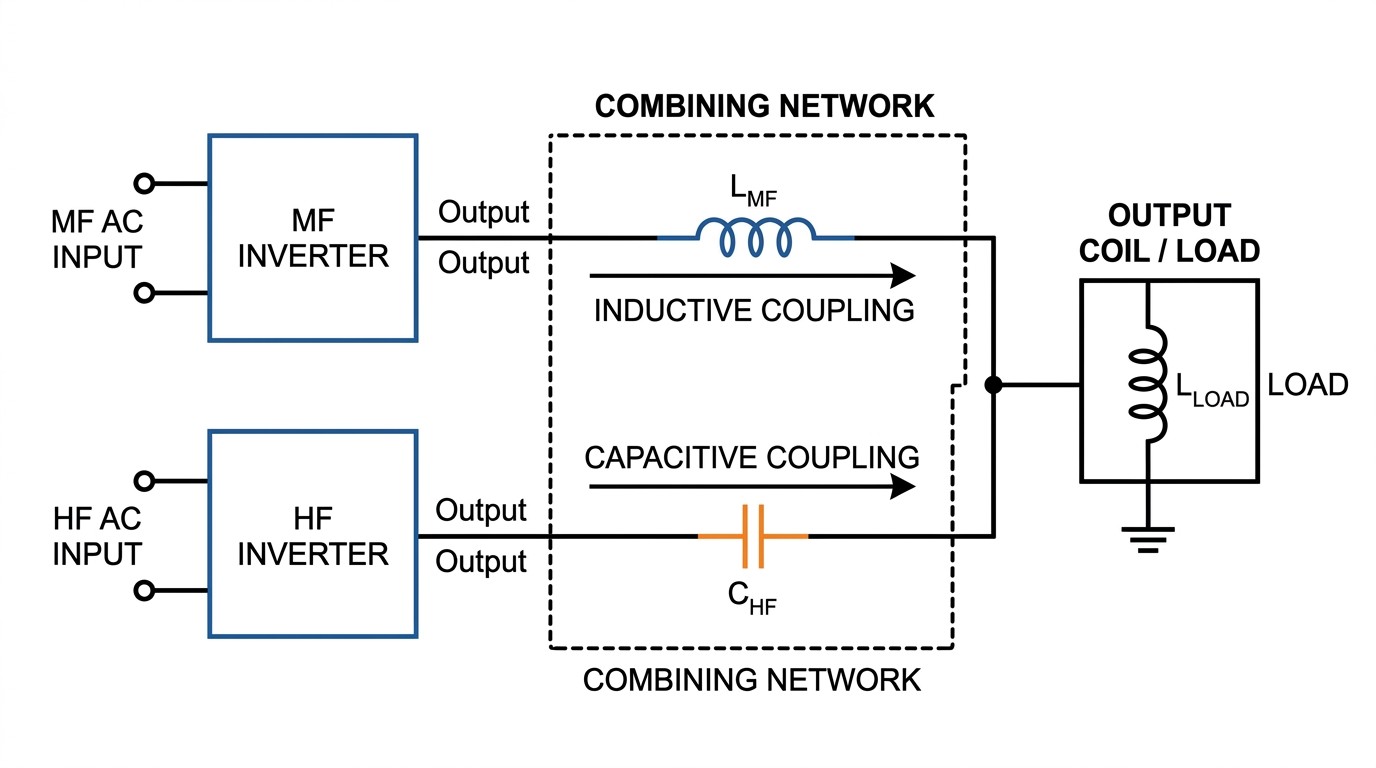
Dual-inverter combining concept.
The source outlines a basic architecture: two inverters, one medium frequency and one high frequency. The low-frequency inverter can be inductively coupled into the coil path so it passes medium-frequency current while rejecting the high-frequency component. Conversely, the high-frequency inverter can be capacitively coupled to pass the high-frequency current while blocking the medium-frequency component.
Even if you don't reproduce this exact design, the concept matters: robust dual-frequency systems must provide frequency-selective paths so the channels do not fight. That is why combining networks are the engineering center of gravity for dual-frequency reliability.
How to Present Dual-Frequency to Stakeholders
Dual-frequency is easier to justify when it is framed in terms stakeholders already understand: risk and process window. Rather than describing it as "two inverters," describe it as a way to reduce the probability of defects caused by unavoidable geometry-driven gradients. Present a before/after comparison using measurable outcomes: surface-to-core spread, hardness profile variation, scrap rate under coupling variation, and cycle time.
This framing also supports good change control. If the capability is justified by specific metrics, then split limits and alarm thresholds can be tied directly to those metrics, keeping production adjustments disciplined.
Acceptance Testing: Prove Both Performance and Robustness
Dual-frequency systems should be accepted with two categories of tests. Performance tests show that the target profile can be achieved (hardness pattern or temperature gradient). Robustness tests show that the profile remains acceptable when you apply realistic disturbances: part-to-coil gap variation, incoming temperature variation, and small throughput changes. A dual-frequency system that only works under perfect conditions will not deliver the promised value.
A Note on Maintenance and Spare Strategy
Because dual-frequency architectures add combining components and additional sensing paths, spare strategy should be reviewed early. Stocking a few high-wear or long-lead items (filters, specific capacitor modules, combining network components, key sensors) can prevent a capability that is valuable in production from becoming unavailable due to minor failures.
FAQ about Simultaneous Dual-Frequency Induction Heating
Q: What's the clearest sign dual-frequency may help?
When you cannot meet both surface and bulk requirements with one frequency without causing defects or sacrificing cycle time.
Q: How do you avoid "mystery tuning" in dual-frequency recipes?
Assign roles to each frequency, change one variable at a time, and log part response metrics alongside power split data.
Q: What commissioning checks are essential?
Verify each channel independently at reduced power, validate combining network temperature rise, confirm measurement separation, and stress test with controlled coupling variation.
Conclusion: Simultaneous Dual-Frequency Induction Heating
Dual-frequency is justified when it measurably widens the process window—quality robustness, cycle time, or energy efficiency. If controlled trials cannot demonstrate that benefit, the simpler single-frequency system is usually the better long-term choice.
If you cannot describe, measure, and control the split in a way operators can follow, the system will drift. Dual-frequency succeeds when it is engineered for repeatability, not when it is treated as an advanced knob.
Keep Learning
Simultaneous Dual-Frequency Induction Heating: When One Frequency Forces the Wrong Compromise
Key Takeaways One frequency, one compromise: When geometry demands both deep bulk heating and controlled surface gradients simultaneously, a single frequency forces an unacceptable trade-off—dual-frequency widens the process window. Give each channel a role: Assign the lower frequency to bulk penetration and the higher frequency to surface shaping. Structured recipe development follows naturally from this separation. Validate with metrics, not opinions: Dual-frequency is justified only when controlled......
Power Supplies by Application Family: Joining, Mass Heating, and Strip Processing
Key Takeaways Joining operations (brazing, soldering, bonding) demand higher frequencies and matching flexibility to handle variable coil coupling and precision surface heating. Mass heating lines (billets, bars, slabs) prioritize continuous duty, efficiency, and ruggedness at high power levels with multi-coil zone control. Strip processing requires architectures that separate control electronics from high-frequency inverter modules to cope with harsh installation environments. Specifying only kW and ......
Simultaneous Dual-Frequency Induction Power: When One Frequency Forces the Wrong Compromise
Key Takeaways Dual-frequency is justified by robustness, not complexity: It should only be adopted when a single frequency forces an unacceptable compromise between surface and bulk heating requirements. Give each frequency a defined role: Assign the lower frequency to bulk heating/penetration and the higher frequency to surface shaping—then develop recipes one variable at a time. The combining network is the engineering center of gravity: Frequency-selective coupling paths, thermal rating for worst-c......
Applying Induction Power Supplies in the Real World: Constraints That Decide Uptime and Quality
Key Takeaways Application constraints dominate real-world performance: Two induction systems with identical kW ratings can behave very differently depending on cable length, cooling water temperature, dust levels, and fixture repeatability. Design for drift, not for perfect day one: Coils deform, filters clog, sensors drift, and connectors loosen under thermal cycling. Baseline monitoring during commissioning is essential. Mechanical repeatability often beats control complexity: Improving fixturing an......
Medium- and High-Frequency Transformers in Induction Systems: Design Drivers Engineers Should Actually Care About
Key Takeaways Not Passive: Transformers set the electrical operating point for the entire induction station—coil voltage, current, capacitor stress, and inverter margin all depend on transformer choice. Frequency Effects: At higher frequencies, winding losses and stray capacitance dominate; a transformer that looks fine on turns ratio can fail a duty-cycle test if loss distribution is wrong. Placement Matters: Moving the transformer and capacitor bank closer to the coil reduces high-frequency loop len......
Load Matching in Induction Heating: Designing for Stability, Efficiency, and Real-World Variation
Key Takeaways Dynamic Load: Induction heating loads are not fixed—coupling, material properties, and temperature all shift impedance during operation, making matching a continuous design challenge. Q Factor Matters: High-Q loads can produce large circulating currents and capacitor stress even at modest delivered kW; design for the worst-case kVA, not just power. Discrete Ranges Win: Transformer taps and capacitor steps that cover discrete matching ranges outperform a single broad-range configuration f......