In-Line Induction Heating of Bars and Rods: Continuous Throughput Without Temperature Surprises
10 min
- Electrothermal Fundamentals of In-Line Induction Heating
- Multi-Coil Systems and Power Supply Configurations
- Managing Electromagnetic Interactions and Voltage Drops
- Copper Shield Plates: Roles and Effects
- Thermal Stress and Cracking Considerations
- Transient Effects and Nose-to-Tail Temperature Profiles
- Practical Design and Operational Recommendations
- FAQ about In-Line Induction Heating of Bars and Rods
Key Takeaways
Electromagnetic Skin Effect: During initial heating, eddy currents concentrate in a thin surface layer, creating steep surface-to-core temperature gradients that must be managed carefully.
Arcing Prevention: Longitudinal voltage drops along bars can cause arcing with support rolls. Alternating coil winding directions or tailored electrical connections are key mitigation strategies.
Copper Shield Plates: Unslotted copper end plates act as Faraday rings to reduce electromagnetic cross-talk and protect equipment, but they reduce coil efficiency and require water cooling.
Crack Prevention: High-carbon steels and cast materials are prone to thermal cracking. Soft-start heating profiles and low frequencies help minimize thermal stress during the initial heating stage.
Nose-to-Tail Effects: Transient heating during start-up and shutdown introduces temperature nonuniformities along bar length, requiring precise power control and coil design to compensate.
Induction heating (IH) has become a cornerstone technology in the continuous production of cylindrical metal products such as bars, rods, billets, and slugs. The integration of casting, reheating, and rolling into a seamless production line demands precise thermal control to ensure product quality and process efficiency. In-line induction heating systems offer rapid, controllable heating, but they also present unique challenges related to temperature uniformity, electromagnetic interactions, and thermal stresses. This article delves into the electrothermal principles, coil design considerations, transient effects, and practical solutions to common problems encountered in in-line induction heating of bars and rods.
Electrothermal Fundamentals of In-Line Induction Heating
Induction heating operates on the principle of electromagnetic induction, where alternating current flowing through coils generates eddy currents within the conductive workpiece. These eddy currents dissipate energy as heat due to the electrical resistivity of the material. In the context of long cylindrical bars and rods, the heating process is complex due to the evolving temperature profile along both the radial and axial directions.
Surface-to-Core Temperature Gradients
At the start of the heating process, the entire bar is ferromagnetic, and the skin effect confines induced currents to a thin surface layer, typically less than 6 mm thick at frequencies above 500 Hz. This results in rapid surface heating with minimal core temperature rise, generating substantial surface-to-core temperature gradients. The low surface temperature at this stage also means heat losses to the environment are minimal, allowing efficient energy transfer.
As heating progresses and the surface temperature approaches the Curie point, the magnetic properties of the steel change dramatically. The surface loses ferromagnetism, causing the magnetic permeability (μr) to drop to unity. This transition reduces coil efficiency and alters the power density distribution, shifting some heating deeper into the subsurface layers where magnetic properties persist. The specific heat capacity peaks near the Curie point, requiring more energy input for temperature increases and further complicating thermal gradients.
Eventually, the entire cross-section becomes nonmagnetic, and the power density distribution assumes a classical exponential decay from the surface inward. This final stage requires careful power management to avoid overheating the surface while ensuring adequate core temperature.
Multi-Coil Systems and Power Supply Configurations
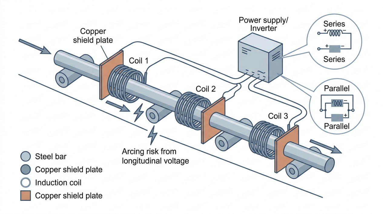
In-line induction heating systems often employ multiple coils arranged sequentially along the production line. These coils may be powered by a single inverter or multiple inverters, with electrical connections configured in series, parallel, or complex combinations to optimize load matching and operational flexibility.
- Series Connection: Coils connected end-to-end share the same current but divide voltage. This configuration suits voltage-source power supplies and simplifies control but may be limited by voltage constraints.
- Parallel Connection: Coils share voltage but divide current, appropriate for current-source supplies. It provides redundancy but requires careful balancing to avoid uneven heating.
- Complex Series/Parallel Combinations: Used for large-diameter billets or high production rates, these configurations balance voltage and current demands and can be powered by multiple inverters for modular control.
The choice of configuration impacts coil efficiency, electromagnetic interactions, and thermal uniformity.
Managing Electromagnetic Interactions and Voltage Drops
Longitudinal Voltage Drop and Arcing Risks
When heating elongated workpieces, the induced eddy currents have both circumferential and longitudinal components. The longitudinal component generates voltage drops along the bar length, which can sum across multiple coils. If the support rolls and grounding points form a closed electrical loop with the workpiece, parasitic currents may flow, leading to arcing between the bar and rolls.
Arcing consequences include:
- Surface damage such as pitting and erosion on both the bar and rolls.
- Premature bearing failure in support rolls.
- Process interruptions and increased maintenance costs.
Coil Winding Arrangements to Mitigate Voltage Drops
One cost-effective approach is to use identical coils with the same winding direction (all clockwise or all counterclockwise). While this simplifies manufacturing and maintenance, it can exacerbate longitudinal voltage build-up.
An alternative is to alternate coil winding directions (e.g., CCW–CW–CCW–CW), which can reduce the net longitudinal voltage by inducing opposing voltage drops in adjacent coils. However, this complicates coil identification and installation.
A more sophisticated solution involves using identical coils with tailored electrical connections to reverse the direction of induced longitudinal voltages without changing coil windings. This approach dramatically reduces total longitudinal voltage and mitigates arcing risks while maintaining coil uniformity.
Split Coil Windings
Split coil windings divide the coil into two sections with opposite longitudinal current directions but consistent circumferential current orientation. This design minimizes longitudinal voltage without causing electromagnetic field cancellation, preserving coil efficiency. Split windings are effective in continuous heating but may create cold spots in static heating scenarios.
Copper Shield Plates: Roles and Effects
Copper shield plates, or end plates, are installed at coil ends for mechanical protection and electromagnetic management. There are two primary types:
- Slotted Plates (Electrically Open Circuit): Provide mechanical support and protect coils from physical damage. They have minimal impact on electromagnetic fields and do not significantly reduce heating of adjacent conductive components.
- Unslotted Plates (Electrically Closed Circuit): Act as electromagnetic shields by inducing eddy currents that generate opposing magnetic fields (“robber ring” or Faraday ring effect). This reduces heating of coil end regions, support rolls, and frames, and diminishes electromagnetic cross-talk between adjacent coils or inverters.
While unslotted plates improve operational stability and protect equipment, they generate heat themselves and require water cooling. They also reduce coil electrical efficiency, especially when coil inner diameter is large, coil length is short, or coil-to-end plate distance is small.
Thermal Stress and Cracking Considerations
Bars and rods made from high-carbon steels, as-cast steels, and cast irons are susceptible to longitudinal and transverse cracks during induction heating. These cracks arise primarily from excessive thermal gradients and stresses, often during the initial heating stage when the core remains cold and brittle.
Mitigation strategies include:
- Employing low frequencies and moderate power densities to reduce surface-to-core temperature gradients.
- Implementing “soft start” heating profiles to gradually raise temperature and allow stress relaxation.
- Using advanced process controls to monitor and adjust heating parameters dynamically.
Note
Casting imperfections generally have minimal impact on eddy current flow and temperature uniformity at low to medium frequencies. However, at higher frequencies (above 30 kHz), localized heating anomalies may occur due to electromagnetic property variations in porous or segregated regions.
Transient Effects and Nose-to-Tail Temperature Profiles
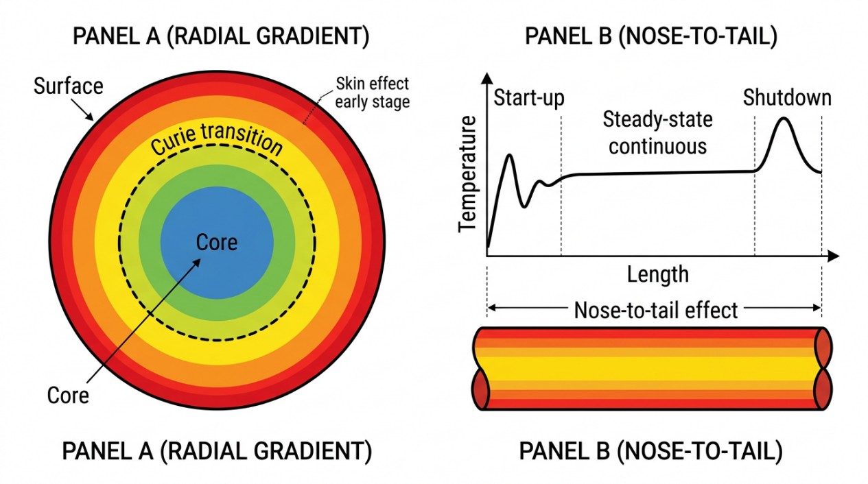
In continuous induction heating lines, transient processes such as start-up and shutdown phases introduce temperature nonuniformities along the bar length, commonly referred to as “nose-to-tail” effects.
- Start-Up: When the leading end of a bar enters the coil, the heating profile is not yet stabilized, causing temperature variations.
- Shutdown: As the trailing end exits the coil, electromagnetic end effects cause a surplus of induced heat, leading to higher temperatures at the bar end compared to its body.
These effects are influenced by coil length, frequency, and power settings. Longer coils and higher frequencies amplify end heating surpluses.
Managing transient effects requires:
- Careful control of coil power during start-up and shutdown.
- Use of coil designs and shielding to minimize electromagnetic end effects.
- Process monitoring to detect and compensate for temperature spikes.
Practical Design and Operational Recommendations
Designing an effective in-line induction heating system for bars and rods involves balancing electromagnetic, thermal, and mechanical factors:
- Coil Design: Optimize coil geometry, winding direction, and electrical connections to minimize longitudinal voltage drops and maximize heating uniformity.
- Power Supply Configuration: Select inverter types and coil connections (series, parallel, or hybrid) based on load characteristics and control requirements.
- Shielding: Employ copper shield plates judiciously to protect equipment and reduce cross-talk, considering the trade-off with coil efficiency.
- Frequency Selection: Use frequencies appropriate to bar diameter and material properties to control skin depth and heating profiles.
- Thermal Management: Implement gradual heating ramps and monitor temperature gradients to prevent cracking and thermal stress damage.
- Process Control: Utilize real-time temperature measurement and feedback systems to maintain consistent heating and compensate for transient effects.
Checklist for In-Line Induction Heating of Bars and Rods
- Design coil windings and electrical connections to minimize longitudinal voltage drops and prevent arcing.
- Use multiple coils with appropriate series/parallel configurations to balance power delivery and load matching.
- Consider alternating coil winding directions or complex electrical connections to reduce parasitic currents.
- Install copper shield plates (slotted or unslotted) at coil ends to protect equipment and reduce electromagnetic interference.
- Select induction frequency based on workpiece diameter and material magnetic properties to optimize skin depth and heating uniformity.
- Implement soft-start heating profiles to reduce thermal gradients and prevent cracking in sensitive materials.
- Monitor and control transient heating phases (start-up and shutdown) to avoid nose-to-tail temperature nonuniformities.
- Employ water cooling for copper shield plates and coils to manage heat dissipation and maintain coil efficiency.
- Use real-time temperature sensors and feedback control systems for dynamic adjustment of coil power.
- Account for casting imperfections and material heterogeneity when setting heating parameters, especially at high frequencies.
FAQ about In-Line Induction Heating of Bars and Rods
Q: Why does arcing occur between the bar and support rolls during induction heating?
Arcing happens when induced eddy currents create longitudinal voltage drops along the bar. If support rolls and grounding points form a closed electrical loop with the workpiece, parasitic currents flow between the bar and rolls, causing arcing. This can damage surfaces, cause premature bearing failure, and increase maintenance costs. Solutions include alternating coil winding directions or using tailored electrical connections to minimize voltage build-up.
Q: What causes cracks in bars during induction heating, and how can they be prevented?
Cracks occur due to excessive thermal gradients between the hot surface and cold core, especially in high-carbon steels and cast materials. During initial heating, the skin effect confines heat to a thin surface layer while the core remains brittle. Prevention strategies include using low frequencies with moderate power, implementing “soft start” heating profiles to gradually raise temperature, and employing dynamic process controls to manage thermal stress.
Q: What is the “nose-to-tail” temperature effect in continuous heating lines?
The nose-to-tail effect refers to temperature variations along the bar length during transient phases. At start-up, the leading end experiences unstable heating profiles. At shutdown, electromagnetic end effects cause the trailing end to receive surplus heat, resulting in higher temperatures than the bar body. These effects are more pronounced with longer coils and higher frequencies, requiring careful power control and process monitoring to maintain temperature uniformity.
Conclusion: In-Line Induction Heating of Bars and Rods
In-line induction heating of bars and rods is a sophisticated process requiring a deep understanding of electromagnetic phenomena, thermal dynamics, and mechanical constraints. By carefully designing coil systems, managing electrical connections, and controlling thermal profiles, manufacturers can achieve continuous throughput with minimal temperature surprises, ensuring product quality and operational reliability.
Keep Learning
Induction Billet Heating: How to Achieve Uniform Heating
Induction billet heating prepares metal for forging, extrusion, or rolling by generating heat inside the workpiece. For steel billets, reaching the required exit temperature is only part of the task: the temperature distribution from surface to core and along the billet must also suit the forming process. Uniformity depends on how frequency, coil geometry, heat transfer, power distribution, and billet movement work together. This guide focuses on through-heating steel billets, particularly in progress......
How to Upgrade a 3D Printer Heated Bed with a Silicone Heater
If your 3D printer heated bed takes too long to reach temperature, develops uneven heating, or struggles to maintain a stable surface temperature, a silicone heater can be a practical upgrade. Faster warm-up and more uniform heat can improve first-layer consistency and reduce temperature-related printing issues. This guide explains how to identify when a heated-bed upgrade is needed, choose a suitable silicone heater, install it safely, and verify the results. Quick Answer A silicone heater can be a s......
How Graphene and MXene Flake Sensors Detect Force
Key Takeaways Flake networks sense force through microstructural change: Graphene and MXene coatings distribute conduction across overlapping platelets whose contacts shift under stretch or pressure, producing measurable resistance changes. Three mechanisms compete: Crack propagation, flake slippage, and quantum tunnelling each dominate at different deformation levels, giving many sensors multiple sensitivity regions rather than one uniform response. The substrate is an active partner: Elastomers, tex......
Conductive 2D Coatings Are a Matching Problem, Not a Miracle Ink
Key Takeaways Ink is a system, not a material: Conductivity depends on the combined effect of flake chemistry, solvent, additives, substrate, coating method, and post-processing—not on the 2D filler alone. Three carbon routes carry different trade-offs: GNPs demand dispersion engineering, GO shifts effort to a reduction step, and MXenes move the bottleneck to synthesis, storage, and oxidation control. Substrate geometry drives method selection: Spray and blade coating suit flat sheets; dip coating nat......
Graphene Heat Spreader Design: Layers and Interfaces
Key Takeaways Conductivity alone is not enough: A record thermal-conductivity value does not guarantee a cooler chip. Effective thickness, interface resistance, hot-spot geometry, and heat-sink connections all belong to the same thermal path. Few-layer graphene can outperform a single layer in practice: A few-layer sheet provides a larger heat-flow cross section and better tolerates transfer, embedding, and defects, even though its intrinsic conductivity is lower. Interface resistance is the bottlenec......
How Graphene Heat Spreaders Cool SOI Chip Hot Spots
Key Takeaways Buried oxide is a thermal bottleneck: SOI's insulating layer improves electrical isolation but traps heat near transistor channels, creating dangerous hot spots that package-level cooling alone cannot fix. Graphene enables lateral heat routing: Placing graphene or few-layer graphene beneath the buried oxide adds a high-conductivity sideways path, redistributing hot-spot energy toward dedicated sinks without removing any heat itself. Multi-source chips benefit most: Finite-element modelin......