
Power Supplies by Application Family: Joining, Mass Heating, and Strip Processing
11 min
- Three Application Families and Their Power-Supply Demands
- Joining Operations: Brazing, Soldering, and Bonding
- Mass Heating Before Forming: Billets, Bars, and Rods
- Strip Processing: Continuous Heating of Thin Sections
- Joining Stations: Why Matching Flexibility Is a Quality Feature
- Mass Heating Lines: Controlling Uniformity, Not Just Temperature
- Strip Processing: Architecture Follows Installation Physics
- Typical Measurement Strategy by Family
- Why "One Cabinet" Is Rarely the Best Strip-Line Answer
- Commissioning Deliverables That Make These Lines Sustainable
- Engineering Consequence: How Frequency Choice Changes Coil Tooling and Operations
- A Practical Acceptance Strategy by Family
- Designing for Changeover and Mixed Production
- Joining Frequencies: A Concrete Example
- Mass Heating: Technology Evolution and Selection Logic
- Why Current Needed for the Same Heating Drops with Frequency
- A Useful Rule: Tie Frequency Selection to What You're Trying to Control
- FAQ about Induction Power Supplies by Application
Key Takeaways
Joining operations (brazing, soldering, bonding) demand higher frequencies and matching flexibility to handle variable coil coupling and precision surface heating.
Mass heating lines (billets, bars, slabs) prioritize continuous duty, efficiency, and ruggedness at high power levels with multi-coil zone control.
Strip processing requires architectures that separate control electronics from high-frequency inverter modules to cope with harsh installation environments.
Specifying only kW and kHz under-specifies real requirements. Start from the process control objective to determine the right architecture.
Three Application Families and Their Power-Supply Demands
Induction power supplies are not one-size-fits-all. The "right" architecture depends on what the process is trying to control: a tiny joint interface, a continuous stream of billets, or a fast-moving steel strip. Each application family pushes design priorities in different directions—power level, frequency, matching flexibility, packaging, and environmental protection.
This guide compares three common application families and explains what changes in power supply requirements and integration strategy.
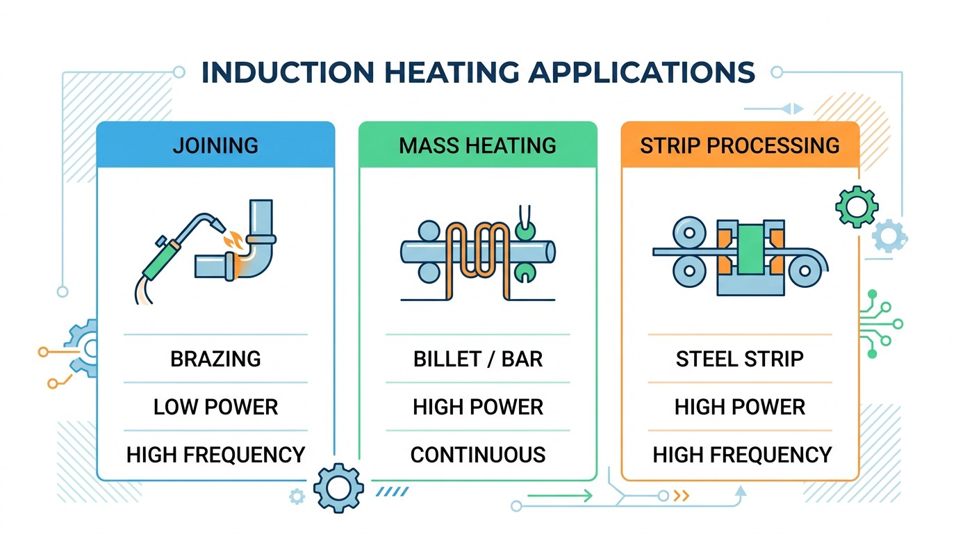
Three application families and the power-supply traits they most often demand.
| Typical Power | Typical Frequency | Design Priority | |
|---|---|---|---|
| Joining (brazing/soldering/bonding) | Low to moderate | Medium to high | Matching flexibility, portability, precision |
| Mass heating (billet/bar/slab) | High to very high | Low to medium | Continuous duty, efficiency, ruggedness |
| Strip processing | High | Medium to high | Efficiency, architecture for harsh layout constraints |
Joining Operations: Brazing, Soldering, and Bonding
Joining is about heating adjacent surfaces precisely so filler material melts and solidifies into a robust joint. The heated zone is intentionally small, and avoiding collateral heating is part of the quality requirement. This typically leads to lower power requirements but higher frequency choices to concentrate heating near surfaces and to support small, maneuverable coils.
In many joining stations, operators manipulate the coil or fixture, which introduces coupling variation during the cycle. The power supply must therefore tolerate high-Q loads and provide broad matching flexibility.
joining or application-specific supply packaging.
Mass Heating Before Forming: Billets, Bars, and Rods
Mass heating is throughput-driven. The goal is uniform through-heating at high power, often continuous duty. Efficiency becomes economically dominant: small differences in efficiency translate to large continuous energy costs. Environmental conditions are often harsh: dust, scale, high ambient heat, vibration.
These systems frequently use multi-coil lines and may allocate power by zone to manage surface-to-core gradients rather than simply hitting an average temperature.
Strip Processing: Continuous Heating of Thin Sections
Strip lines resemble mass heating in throughput and duty cycle, but workpiece thickness forces higher frequencies for coupling and efficiency. Installation constraints can be extreme (height, heat, dust, proximity to aggressive atmospheres). Architectures that split control/rectification from the high-frequency inverter module are common when the induction head must live near the strip and the main electronics must remain serviceable.
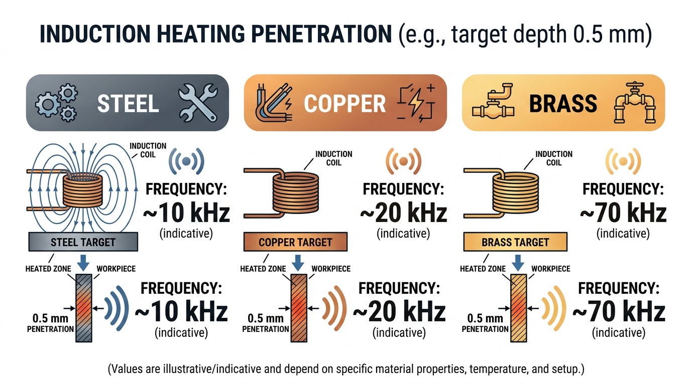
Indicative frequency differences for similar penetration targets across materials.
Joining Stations: Why Matching Flexibility Is a Quality Feature
In joining, the coil is often a tool held close to the work and sometimes manipulated during the cycle. That makes the electrical load variable by design. A supply that cannot tolerate load variation forces operators to slow down, rework fixtures, or accept inconsistent heating.
For that reason, matching flexibility should be treated as a quality feature, not a convenience. The supply must remain stable across a realistic range of coil geometries and coupling conditions. Logging and alarm behavior should support operator workflow rather than requiring expert interpretation.
Mass Heating Lines: Controlling Uniformity, Not Just Temperature
Forming processes often care more about gradients than average temperature. If the surface is too hot, oxidation and defects increase. If the core is too cold, forming loads rise and die wear increases. Multi-coil lines address this by shaping a thermal profile along the line.
This is where power supply modularity matters. Independent control per coil (or per zone) can improve uniformity and efficiency by allocating power where it is most effective.
Strip Processing: Architecture Follows Installation Physics
Strip lines can force the induction head into physically hostile locations. The best architectures separate what must be near the strip (HF inverter + coil module) from what should remain accessible (rectifier/control). DC transmission over distance is often the practical solution.
If you specify strip equipment without considering these layout realities, the project often ends up with expensive retrofits.
Typical Measurement Strategy by Family
In joining stations, the most useful measurements often include delivered energy per cycle and a simple temperature confirmation near the joint, because small timing differences can matter. In mass heating lines, the most useful measurements include power per zone and line speed, because the thermal history is distributed. In strip lines, throughput and exit temperature (or coating cure indicators) often dominate, and the system must remain stable under continuous duty.
The power supply should support these strategies by providing stable signals, exportable logs, and alarms that map to physical causes.
A Note on Cost Drivers
Joining systems are often limited by matching flexibility and coil tooling rather than raw kW cost. Mass heating systems are limited by energy cost and cooling cost over life of the line. Strip systems are limited by installation complexity and service access. If you evaluate all three families with the same procurement lens, you will choose the wrong trade-offs.
Why "One Cabinet" Is Rarely the Best Strip-Line Answer
In strip processing, the process station may be physically far from where technicians can safely service electronics. Separating rectification/control from the HF module is not an exotic choice; it is a maintainability choice. This architecture also shortens the HF loop and can improve efficiency.
Commissioning Deliverables That Make These Lines Sustainable
Regardless of application family, insist on a commissioning package that includes: baseline signatures, verified alarm thresholds, and a documented changeover procedure. Joining stations need coil-ID and matching documentation; mass heating lines need zone power profiles and speed envelopes; strip lines need verified thermal performance at maximum throughput and worst-case ambient conditions. When these deliverables exist, the line remains stable long after the commissioning team leaves.
Engineering Consequence: How Frequency Choice Changes Coil Tooling and Operations
In joining, higher frequency often enables smaller tooling, but it can also increase sensitivity to coil wear and positioning. In mass heating, lower frequency supports deeper heating, but coil lines become physically larger and power levels increase, which raises both electrical and mechanical design challenges. In strip processing, frequency selection is intertwined with strip thickness and speed; the chosen band must maintain coupling efficiency without creating unacceptable surface overheating.
These operational consequences matter because they determine how often coils must be replaced, how often the line must be tuned, and how stable the process remains under normal variation.
A Practical Acceptance Strategy by Family
For joining systems, acceptance should include tests across coil variants and deliberate coupling offsets to confirm matching flexibility and stability. For mass heating lines, acceptance should include steady-state thermal runs at maximum duty cycle with verified zone power profiles and exit temperature distribution. For strip lines, acceptance should include maximum throughput tests under worst-case ambient conditions, plus verification that the architecture supports service access without shutting down the entire line.
If these acceptance tests are not specified, projects often "pass" on paper but fail in practice.
Designing for Changeover and Mixed Production
Many induction installations are asked to run more than one product. Joining cells may switch fixtures daily, and heat-treat cells may run multiple part variants on the same machine. In these environments, the power supply must support controlled changeover rather than improvisation.
A practical changeover strategy includes coil identification, documented matching configuration, and a standard verification cycle that produces a known electrical signature. If the signature is off, the changeover is not complete. This approach prevents drift and reduces the temptation to "tune until it works," which is how validated processes slowly degrade.
In continuous mass heating lines, the equivalent challenge is throughput variation. If line speed changes, the thermal history changes. Systems that can redistribute power by zone and maintain stable control under speed changes tend to produce more consistent exit temperature distributions.
In strip lines, product mix may involve thickness and coating changes. The induction system must remain stable under those changes while maintaining service access and thermal margin. Here, architecture choices (distributed HF module vs centralized cabinet) often determine how maintainable the line is under frequent adjustments.
Joining Frequencies: A Concrete Example
If you target roughly 0.5 mm penetration depth, a heating frequency on the order of ~10 kHz may be appropriate for carbon steel under certain low power density, room-temperature conditions, while copper may require ~20 kHz and brass ~70 kHz for the same penetration depth. The exact numbers shift with temperature and power density, but the principle is durable: different materials drive different frequency needs for the same thermal objective.
This is also why joining supplies often favor higher frequency: higher frequency can reduce the current required for a given heating effect, which in turn enables smaller coils and smaller conductors. That size reduction cascades into more portable equipment and more practical access to confined joints.
Mass Heating: Technology Evolution and Selection Logic
For mass heating, the evolution from line-frequency supplies and motor-generator sets toward SCR-based and transistorized supplies has shaped today's selection landscape. The practical decision today often comes down to frequency and economics: transistorized solutions are often attractive at ~10 kHz and above due to compactness, while SCR solutions remain common at very high power and lower frequencies.
For the integrator, the actionable takeaway is to align topology selection with where your process sits on the power-frequency map, and to validate continuous-duty thermal performance. In mass heating, steady-state thermal stability and energy efficiency are usually more important than peak transient response.
Why Current Needed for the Same Heating Drops with Frequency
At higher frequency, less current can be needed to achieve the same heating effect at the surface. In engineering terms, this often means the coil and the conductors feeding it can be smaller, which reduces copper cost and makes tooling easier to handle. It also means matching components can often be more compact because the magnetic cores and current paths scale down. This is one reason portable joining supplies exist as a mainstream industrial product rather than as a niche solution.
Design Note
The frequency benefit is only realized when layout is disciplined. High frequency also increases AC resistance and sensitivity to parasitics, so compactness must be paired with good conductor design and capacitor placement.
A Useful Rule: Tie Frequency Selection to What You're Trying to Control
When teams debate frequency, the simplest resolution is to restate the controlled variable. If you are controlling a small surface region (a joint interface), higher frequency is usually justified. If you are controlling bulk temperature for forming, lower frequency and longer coil lines are usually justified. If you are controlling thin strip temperature at high throughput, higher frequency is often required for coupling efficiency, but architecture must be chosen to keep the high-frequency loop physically short.
This rule prevents "frequency debates" from becoming personal preference and keeps decisions tied to measurable process requirements.
FAQ about Induction Power Supplies by Application
Q: Why are joining power supplies often high frequency even at low kW?
Because joining is surface-focused and benefits from small coils and conductors. Higher frequency can achieve the required heating with smaller current and more compact equipment.
Q: Why do mass heating systems emphasize efficiency and continuous duty?
They run at high power for long periods. Even small losses translate into significant energy cost and heat rejection requirements.
Q: What is the most common strip-line integration mistake?
Trying to transmit high-frequency AC over long distances. Many strip installations benefit from transporting DC and placing the high-frequency inverter near the coil to reduce losses and detuning sensitivity.
Conclusion: Specify the System Around What You Must Control
If you specify only kW and kHz, you will under-specify the real requirements: matching range, cable length constraints, environmental protection, and control/monitoring strategy. Start from the process control objective—precision joint heating, uniform bulk heating, or continuous strip heating—and the right architecture becomes much clearer.
Keep Learning
Simultaneous Dual-Frequency Induction Heating: When One Frequency Forces the Wrong Compromise
Key Takeaways One frequency, one compromise: When geometry demands both deep bulk heating and controlled surface gradients simultaneously, a single frequency forces an unacceptable trade-off—dual-frequency widens the process window. Give each channel a role: Assign the lower frequency to bulk penetration and the higher frequency to surface shaping. Structured recipe development follows naturally from this separation. Validate with metrics, not opinions: Dual-frequency is justified only when controlled......
Power Supplies by Application Family: Joining, Mass Heating, and Strip Processing
Key Takeaways Joining operations (brazing, soldering, bonding) demand higher frequencies and matching flexibility to handle variable coil coupling and precision surface heating. Mass heating lines (billets, bars, slabs) prioritize continuous duty, efficiency, and ruggedness at high power levels with multi-coil zone control. Strip processing requires architectures that separate control electronics from high-frequency inverter modules to cope with harsh installation environments. Specifying only kW and ......
Simultaneous Dual-Frequency Induction Power: When One Frequency Forces the Wrong Compromise
Key Takeaways Dual-frequency is justified by robustness, not complexity: It should only be adopted when a single frequency forces an unacceptable compromise between surface and bulk heating requirements. Give each frequency a defined role: Assign the lower frequency to bulk heating/penetration and the higher frequency to surface shaping—then develop recipes one variable at a time. The combining network is the engineering center of gravity: Frequency-selective coupling paths, thermal rating for worst-c......
Applying Induction Power Supplies in the Real World: Constraints That Decide Uptime and Quality
Key Takeaways Application constraints dominate real-world performance: Two induction systems with identical kW ratings can behave very differently depending on cable length, cooling water temperature, dust levels, and fixture repeatability. Design for drift, not for perfect day one: Coils deform, filters clog, sensors drift, and connectors loosen under thermal cycling. Baseline monitoring during commissioning is essential. Mechanical repeatability often beats control complexity: Improving fixturing an......
Medium- and High-Frequency Transformers in Induction Systems: Design Drivers Engineers Should Actually Care About
Key Takeaways Not Passive: Transformers set the electrical operating point for the entire induction station—coil voltage, current, capacitor stress, and inverter margin all depend on transformer choice. Frequency Effects: At higher frequencies, winding losses and stray capacitance dominate; a transformer that looks fine on turns ratio can fail a duty-cycle test if loss distribution is wrong. Placement Matters: Moving the transformer and capacitor bank closer to the coil reduces high-frequency loop len......
Load Matching in Induction Heating: Designing for Stability, Efficiency, and Real-World Variation
Key Takeaways Dynamic Load: Induction heating loads are not fixed—coupling, material properties, and temperature all shift impedance during operation, making matching a continuous design challenge. Q Factor Matters: High-Q loads can produce large circulating currents and capacitor stress even at modest delivered kW; design for the worst-case kVA, not just power. Discrete Ranges Win: Transformer taps and capacitor steps that cover discrete matching ranges outperform a single broad-range configuration f......