
Induction Power Supply Topologies: A Practical Guide to Converters, Inverters, and Matching Networks
11 min
- The Universal Block Diagram (Why It’s Still Useful)
- Converter / Rectifier Options: What Changes in the Plant
- Inverter Families: Voltage-Fed vs. Current-Fed as an Integration Decision
- Where Load Matching Lives (and Why Distance Matters)
- Comparative Table: What Topology Choices Change
- How Topology Choices Show Up During Commissioning
- Power Quality: Why Partial Load Is Where Problems Appear
- Packaging Choices: Unitized vs. Distributed Heat Stations
- Protection and Fault Philosophy: A Hidden Topology Difference
- A Simple Selection Matrix for Early Specs
- Deep Dive: How the Same kW Can Produce Very Different Waveforms and Stress
- Control Interfaces and Diagnostics: What Makes Integration Fast
- Converter Control Speed and Why It Matters for Induction
- Harmonics and Instrumentation: Why Power Quality Isn’t Only a Utility Issue
- FAQ about Induction Power Supply Topologies
Key Takeaways
Point 1: Topology choices determine input power quality, response speed, detuning tolerance, and physical constraints in real installations.
Point 2: Converter options (diode vs SCR vs active front end) significantly affect partial-load power factor and plant power quality.
Point 3: Inverter types (voltage-fed vs current-fed) dictate protection philosophy and sensitivity to load changes, while matching network placement is driven by cable length limitations.
Induction heating power supplies are often discussed as if they are interchangeable “black boxes” defined by nameplate kW and kHz. In real installations, topology choices determine whether the system behaves calmly or constantly fights itself: input power quality, response speed, detuning tolerance, cable length constraints, and how much matching hardware must live near the coil.
This guide organizes modern induction power supplies into a clear taxonomy—converter (AC–DC), inverter (DC–AC), and matching network—so engineering teams can specify equipment with fewer surprises and integrate it into real plant layouts.
The Universal Block Diagram (Why It’s Still Useful)
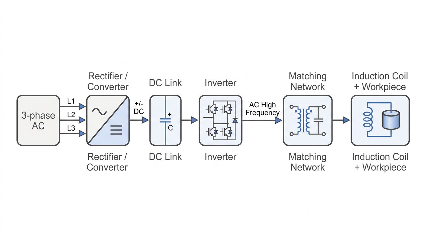
Almost every industrial induction power supply can be reduced to the same functional chain. The differences are in how each block is implemented and how control authority is distributed.
At a high level, the job is simple: take three‑phase line power, produce a DC link, switch it into single‑phase AC at the heating frequency, then transform and tune that output so the coil sees the right voltage/current at the right phase angle.
Converter / Rectifier Options: What Changes in the Plant
The converter stage is not only about making DC; it sets the tone for how the system interacts with the grid. Two supplies with the same kW output can behave very differently at partial load depending on converter design.
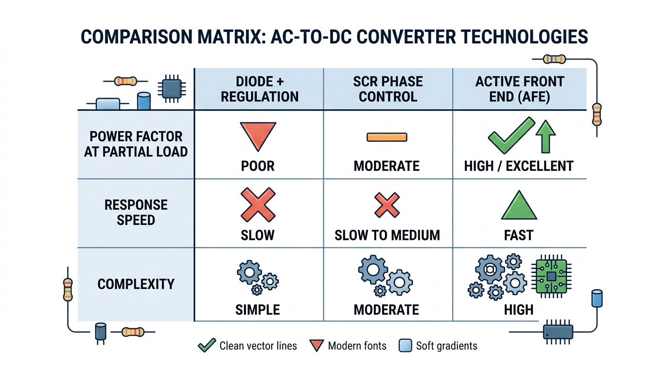
A diode bridge front end is robust and common, but it typically provides limited DC bus control. SCR phase-controlled rectifiers can regulate DC by firing angle, but they may degrade input power factor at reduced output—an increasing concern under modern power-quality standards. Active front ends and switch-mode regulation strategies can maintain better power factor and faster control response, at the cost of additional complexity.
The practical engineering question is not “which is best,” but “which fits our duty cycle and power-quality constraints.” A continuous process that runs near full load may tolerate a simpler converter better than a process that lives at partial load most of the day.
Inverter Families: Voltage-Fed vs. Current-Fed as an Integration Decision
The inverter stage synthesizes the heating-frequency waveform. Industrial discussions often separate inverters into voltage-fed and current-fed families because that choice influences protection philosophy, waveform characteristics, and sensitivity to load variation.
Voltage-fed inverters typically operate from a stiff DC link and can be compact—one reason they are common in transistorized medium and high-frequency systems. Current-fed inverters behave more like controlled current sources, which can be advantageous in certain power ranges but impose different constraints on commutation and protection.
Regardless of family, what matters during integration is how the inverter behaves when the load changes: coil coupling drift, part temperature drift, and high-Q conditions. This is where vendor “kW/kHz” specs are not enough; you need to understand the acceptable operating envelope.
Where Load Matching Lives (and Why Distance Matters)
Induction systems are frequently “load resonant,” meaning the coil + capacitors form the resonant tank. Matching hardware (transformers, capacitor banks, taps/steps) adapts inverter output to coil requirements.
If the coil is close, a unitized cabinet can package inverter + transformer + capacitors compactly. If the coil is far away, transmitting high-frequency power over long leads creates loss, voltage drop, and parasitic resonance risk. In those cases, many systems move the matching station (or even the inverter) closer to the coil, and transport DC over distance instead of high-frequency AC.
Comparative Table: What Topology Choices Change
| Design Choice | What It Optimizes | Typical Trade-Off |
|---|---|---|
| Simple diode rectifier | Robustness, cost | Less DC bus control |
| SCR phase-controlled rectifier | DC regulation capability | Partial-load power factor penalties |
| Active front end | Power quality, fast response | Higher complexity/cost |
| Voltage-fed inverter | Compactness, high frequency | Sensitive to detuning if poorly matched |
| Current-fed inverter | Certain robustness characteristics | Different protection/commutation constraints |
| Remote matching station | Long cable feasibility | More distributed equipment |
How Topology Choices Show Up During Commissioning
Commissioning is where topology stops being theory. If the converter strategy provides slow regulation, the line will feel sluggish during ramps and may overshoot thermal targets when throughput changes. If the inverter strategy is sensitive to detuning, small coupling changes will cause nuisance trips or audible instability. If matching is too narrow, operators will compensate by changing frequency or time, which changes the physics of heating.
A useful way to evaluate a system is to think in terms of where control authority lives. Some systems regulate primarily through DC bus control, some through inverter modulation, and some through frequency shift. Each approach can work, but each produces different process behavior. Engineers should explicitly ask: what happens to frequency when I change power? If frequency moves a lot, then power changes also change penetration behavior.
Power Quality: Why Partial Load Is Where Problems Appear
Many plants discover power-quality issues not at full load, but at partial load. If a converter approach degrades power factor at reduced output, the plant can see penalties or internal compliance failures even though the machine “works.” Active front ends and modern regulation can reduce that risk, but they must be evaluated against cost and maintenance strategy.
If your process spends most of its time below rated output—common in flexible job shops or multi-part lines—ask for input power factor and harmonic behavior across the operating range, not just at nameplate.
Packaging Choices: Unitized vs. Distributed Heat Stations
A compact unitized cabinet can be excellent in automated cells where the coil is close. The problems start when plant layout forces distance. High-frequency transmission over long distance increases loss and adds parasitics; it also complicates grounding and makes troubleshooting harder.
Distributed architectures—where a rectifier/control cabinet stays on the floor and an inverter/matching module sits near the coil—often solve these issues. The engineering work shifts from “one cabinet” to “system integration,” but the result is usually more robust.
A Short Vendor Interview Script
When vendor discussions become vague, bring them back to specific behaviors.
- What is the maximum allowed distance from inverter to tank, and what assumptions does that include?
- How does the system indicate detuning, and what does it do automatically to protect itself?
- What is the allowable load Q range, and how does it change with frequency?
- What measurements are logged per cycle, and can they be exported for QA?
These questions quickly separate “rated capability” from “production robustness.”
Protection and Fault Philosophy: A Hidden Topology Difference
Two supplies can deliver the same kW, yet behave very differently during faults. Some architectures trip quickly on detuning and require manual reset; others gracefully reduce output and hold a safe operating point while alarming. That behavior is partly control design, but it is also influenced by topology and sensing.
Ask explicitly how the system handles common events: momentary coupling loss, coil short events, coolant flow dips, and line voltage sags. A “fast trip” philosophy can be correct for safety, but if it triggers on normal variation, it becomes downtime.
A Simple Selection Matrix for Early Specs
This matrix keeps discussions tied to plant reality rather than brochure terms.
| If your reality is… | You should prioritize… |
|---|---|
| Frequent partial-load operation | Converter strategy with good power quality at partial load |
| Long distance to the coil | Distributed architecture / remote heat station capability |
| High-Q loads common | Robust detuning sensing, matching range, capacitor ratings |
| Highly automated cells | Compact unitized packaging, fast response control |
Final Note: Choose the Simplest Topology That Meets the Real Requirements
Teams sometimes over-specify topology because it sounds safer. A better approach is to specify the behaviors that matter—power quality at operating range, cable-length feasibility, detuning tolerance, and diagnostics—then select the simplest architecture that demonstrates those behaviors with data.
Deep Dive: How the Same kW Can Produce Very Different Waveforms and Stress
When two vendors both claim “100 kW, 10–100 kHz,” engineers often assume the output looks similar. In practice, waveform shape and stress distribution can differ enough to matter for coil life and process repeatability. Some inverters produce near-sinusoidal current in the tank; others produce switched waveforms that rely on the tank to filter. Both can work, but the measurement, EMC behavior, and protection margins differ.
This is why it is valuable to ask for typical output waveforms, not just RMS values. If a system produces higher peak voltage for the same RMS, insulation and arcing risk change. If peak current is higher, mechanical forces on the coil change. If switching edges are fast, coupling to nearby sensors and wiring increases and grounding discipline becomes more important.
In high-Q loads, waveform differences can be amplified. A small change in how the inverter transitions or how it detects commutation can produce large differences in nuisance trips. For system integrators, the practical lesson is to evaluate the supply with your coil family and your installation geometry, not only with generic test loads.
Control Interfaces and Diagnostics: What Makes Integration Fast
Modern induction systems increasingly live inside automated lines. That means integration is not only electrical; it is also controls engineering. A topology that provides fast power response but weak diagnostics can still be a poor choice if commissioning requires guesswork.
Look for practical diagnostics: clear detuning indicators, logged kW/kVA/current/voltage/frequency, and time-stamped faults that can be correlated with motion events. Ask whether these signals are available through standard industrial interfaces and whether the vendor supports exporting data for QA.
A simple benchmark is whether the system can explain itself. If a trip occurs, can you determine in minutes whether it was cooling, mismatch, motion, or a true electrical fault? Topology and sensing choices strongly influence that answer.
Converter Control Speed and Why It Matters for Induction
One point that is easy to overlook is that converter choice affects control response time. The source notes that phase-controlled rectifiers have necessarily slow control response because they act on the input line frequency. That matters when the induction process requires fast and repeatable ramps: the ability to reach set power quickly at heat-on and to drop power quickly at heat-off. If the power supply cannot repeat ramps, the thermal recipe is not repeatable even if steady-state kW is accurate.
This is also why many modern systems distribute control authority: some regulate the DC link, some regulate at the inverter stage, and some blend both. From an integration viewpoint, the question is not “which block regulates,” but whether the overall system can deliver the time-domain behavior your process requires.
Harmonics and Instrumentation: Why Power Quality Isn’t Only a Utility Issue
Another detail in the source is that non-sinusoidal currents contain harmonics, and high-frequency harmonics and magnetic fields can interfere with sophisticated instruments that measure power factor, sometimes producing erroneous readings. In real plants, this shows up as confusing diagnostics: meters disagree, or the system appears to violate a spec while the actual delivered heating is stable.
The practical mitigation is to treat measurement and grounding as part of the power supply system. Specify how kW and kVA are measured (true RMS capability, bandwidth), and ensure the installation follows the vendor’s grounding and bonding guidance. Doing this early prevents weeks of debugging “phantom” power-quality issues.
FAQ about Induction Power Supply Topologies
Q: What topology question should be asked first in a selection meeting?
Ask how the system controls output power across the operating range: DC bus regulation, inverter modulation, frequency shifting, or a combination. That answer predicts both process behavior and power-quality impact.
Q: Why does cable length force architectural changes?
At heating frequencies, long leads add loss and parasitic inductance/capacitance that can destabilize the resonant tank. Moving matching/inverter hardware closer to the coil often improves efficiency and stability.
Q: What evidence should you request from vendors beyond nameplate ratings?
Request efficiency vs. power, input power factor vs. power, acceptable Q/load range, and any limits on distance between inverter and coil/matching station.
Conclusion: Topology Is a Process Decision
Choosing a topology is not a theoretical exercise. It determines how your induction machine behaves when the real world happens: line voltage variation, coupling drift, dust, heat, and operators swapping coils. When teams can speak in the language of converter + inverter + matching, specifications become clearer and commissioning becomes faster.
Keep Learning
Simultaneous Dual-Frequency Induction Heating: When One Frequency Forces the Wrong Compromise
Key Takeaways One frequency, one compromise: When geometry demands both deep bulk heating and controlled surface gradients simultaneously, a single frequency forces an unacceptable trade-off—dual-frequency widens the process window. Give each channel a role: Assign the lower frequency to bulk penetration and the higher frequency to surface shaping. Structured recipe development follows naturally from this separation. Validate with metrics, not opinions: Dual-frequency is justified only when controlled......
Power Supplies by Application Family: Joining, Mass Heating, and Strip Processing
Key Takeaways Joining operations (brazing, soldering, bonding) demand higher frequencies and matching flexibility to handle variable coil coupling and precision surface heating. Mass heating lines (billets, bars, slabs) prioritize continuous duty, efficiency, and ruggedness at high power levels with multi-coil zone control. Strip processing requires architectures that separate control electronics from high-frequency inverter modules to cope with harsh installation environments. Specifying only kW and ......
Simultaneous Dual-Frequency Induction Power: When One Frequency Forces the Wrong Compromise
Key Takeaways Dual-frequency is justified by robustness, not complexity: It should only be adopted when a single frequency forces an unacceptable compromise between surface and bulk heating requirements. Give each frequency a defined role: Assign the lower frequency to bulk heating/penetration and the higher frequency to surface shaping—then develop recipes one variable at a time. The combining network is the engineering center of gravity: Frequency-selective coupling paths, thermal rating for worst-c......
Applying Induction Power Supplies in the Real World: Constraints That Decide Uptime and Quality
Key Takeaways Application constraints dominate real-world performance: Two induction systems with identical kW ratings can behave very differently depending on cable length, cooling water temperature, dust levels, and fixture repeatability. Design for drift, not for perfect day one: Coils deform, filters clog, sensors drift, and connectors loosen under thermal cycling. Baseline monitoring during commissioning is essential. Mechanical repeatability often beats control complexity: Improving fixturing an......
Medium- and High-Frequency Transformers in Induction Systems: Design Drivers Engineers Should Actually Care About
Key Takeaways Not Passive: Transformers set the electrical operating point for the entire induction station—coil voltage, current, capacitor stress, and inverter margin all depend on transformer choice. Frequency Effects: At higher frequencies, winding losses and stray capacitance dominate; a transformer that looks fine on turns ratio can fail a duty-cycle test if loss distribution is wrong. Placement Matters: Moving the transformer and capacitor bank closer to the coil reduces high-frequency loop len......
Load Matching in Induction Heating: Designing for Stability, Efficiency, and Real-World Variation
Key Takeaways Dynamic Load: Induction heating loads are not fixed—coupling, material properties, and temperature all shift impedance during operation, making matching a continuous design challenge. Q Factor Matters: High-Q loads can produce large circulating currents and capacitor stress even at modest delivered kW; design for the worst-case kVA, not just power. Discrete Ranges Win: Transformer taps and capacitor steps that cover discrete matching ranges outperform a single broad-range configuration f......