
Applying Induction Power Supplies in the Real World: Constraints That Decide Uptime and Quality
10 min
- Why "Application Engineering" Matters More Than Nameplate Ratings
- Constraint 1: Duty Cycle and Thermal Reality
- Constraint 2: Load Variation and Mechanical Repeatability
- Constraint 3: Cable Length and Layout Parasitics
- Constraint 4: Power Quality and Grid Interaction
- Constraint 5: Contamination and Harsh Environments
- Comparison Table: Which Constraints Hurt Which Applications
- A Practical Reliability Mindset: Design for What Drifts
- Human Factors: Preventing "Creative Tuning"
- A Lightweight Quarterly Audit That Catches Most Problems
- Process Transitions: Startup, Stops, and Upsets
- Data as a Maintenance Tool (Not Just QA)
- Safety and Housekeeping Are Engineering Requirements
- The One Metric Many Teams Forget: Energy per Part
- Turning Constraints into Requirements: A Template You Can Use
- The Economics of Margin
- A Note on Documentation: Keep the Line Repeatable
- Field-Proven Practices for Harsh Environments
- Inline Heat Treatment: The Hidden Importance of Ramp Repeatability
- Floor Space and Integration: Compactness as a Reliability Feature
- A Short Acceptance Test That Predicts Production Behavior
- FAQ about Applying Induction Power Supplies
Key Takeaways
Application constraints dominate real-world performance: Two induction systems with identical kW ratings can behave very differently depending on cable length, cooling water temperature, dust levels, and fixture repeatability.
Design for drift, not for perfect day one: Coils deform, filters clog, sensors drift, and connectors loosen under thermal cycling. Baseline monitoring during commissioning is essential.
Mechanical repeatability often beats control complexity: Improving fixturing and coil positioning delivers larger process gains than adding sophisticated control algorithms.
Energy per part is the forgotten metric: Tracking energy consumption per unit reveals coupling efficiency loss and system degradation before scrap appears.
Why "Application Engineering" Matters More Than Nameplate Ratings
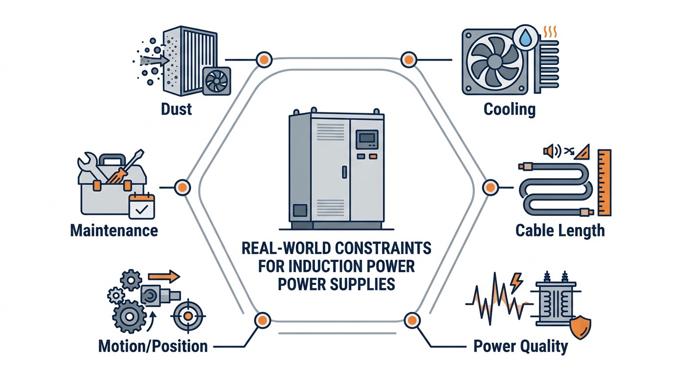
Real-world constraints that must be engineered, not hoped away.
Two systems with the same rated kW can behave very differently under the same process because application constraints change the electrical environment. A machine that is stable on the factory floor can become unstable after installation if the coil is farther away, the cooling water is warmer, or dust accumulation changes insulation behavior.
Instead of treating these as "commissioning issues," treat them as design inputs.
Constraint 1: Duty Cycle and Thermal Reality
Compact/unitized equipment considerations.
Intermittent surface heating and continuous mass heating stress power electronics differently. Continuous systems must survive steady-state thermal loading for hours; intermittent systems often suffer from thermal cycling and repeated peak stress. In both cases, cooling design and derating behavior matter more than the headline rating.
Constraint 2: Load Variation and Mechanical Repeatability
Coupling variation is not an electrical nuisance; it is often a mechanical problem. If fixtures allow the part-to-coil gap to wander, electrical control will spend its effort protecting the inverter rather than following the recipe. Improving fixturing repeatability can deliver larger gains than adding control complexity.
Constraint 3: Cable Length and Layout Parasitics
At heating frequencies, cables and buswork are part of the resonant system. Long runs add loss and introduce parasitic inductance/capacitance that can cause detuning sensitivity. If the coil must be remote, consider moving matching hardware closer to the coil or transporting DC to a remote inverter module.
Constraint 4: Power Quality and Grid Interaction
Modern plants often enforce power factor and harmonic limits. Converter topology determines whether partial-load operation creates unacceptable power factor behavior. If your process spends much of its time at reduced power, power quality becomes a selection criterion rather than a compliance afterthought.
Constraint 5: Contamination and Harsh Environments
Conductive dust, high ambient temperatures, and coolant mist are common around forging and heat-treating operations. Dust can create tracking paths on high-voltage components. High ambient temperature reduces cooling margin. These are predictable hazards that require cabinet sealing, filtration, and maintenance planning.
Comparison Table: Which Constraints Hurt Which Applications
| Often Most Severe In | Why It Matters | |
|---|---|---|
| Conductive dust | Forging / mass heating areas | Tracking, shorts, insulation aging |
| Cable length | Remote heat stations | Loss, detuning, voltage stress |
| Partial-load power factor | Variable throughput lines | Utility compliance and cost |
| Mechanical positioning drift | Close-coupled heat treating | Heating pattern changes |
| Cooling variability | High duty-cycle equipment | Trips, accelerated aging |
A Practical Reliability Mindset: Design for What Drifts
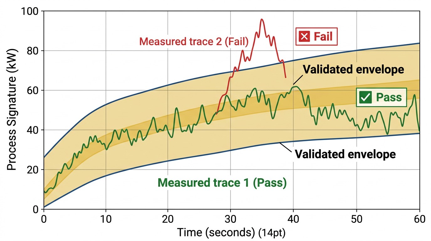
Commissioning golden envelope for drift detection.
Induction lines rarely fail with a single dramatic event. More often, they drift into trouble. Coil geometry changes as copper work-hardens and is repaired. Filters clog and reduce cooling flow. Contact surfaces oxidize and increase resistance. Sensors drift out of calibration.
A robust application plan assumes drift and builds in detection. Baseline electrical signatures during commissioning and re-run them periodically. Trend cooling flow and inlet temperature. Inspect high-stress joints on a schedule rather than waiting for a trip.
Human Factors: Preventing "Creative Tuning"
Many quality escapes start as well-intentioned troubleshooting. An operator sees a temperature drift and adjusts frequency because it "seems to help." That might restore temperature, but it may also change penetration and cause hidden metallurgical changes.
A better approach is to restrict which knobs are allowed in production and to provide clear diagnostics that point to likely causes (cooling drift, positioning drift, matching range mismatch). When the right action is obvious, teams stop inventing new recipes under pressure.
A Lightweight Quarterly Audit That Catches Most Problems
A short audit can prevent many failures:
- Verify branch cooling flow and inlet temperature at the machine.
- Compare a standard test recipe signature to the commissioning baseline.
- Inspect cabinet contamination and filter condition.
- Verify interlocks and alarm thresholds function.
This audit turns induction reliability into routine maintenance rather than heroic debugging.
Process Transitions: Startup, Stops, and Upsets
Many induction lines fail stability tests not during steady operation but during transitions. A cold load at startup behaves differently than a hot, continuously running load. Line stops change convection and radiation losses, and restarts often see different coupling because fixtures and coils have moved thermally.
Treat startup and restart behavior as part of the specification. Define ramp limits, preheat steps, and the acceptable behavior during brief throughput dips. A system that only works in steady state is not production-ready.
Data as a Maintenance Tool (Not Just QA)
If you log kW, current, voltage, and a match indicator, you can detect drift before it becomes scrap. For example, a gradual rise in current required to deliver the same kW often points to worsening coupling, connector resistance increase, or cooling degradation.
When maintenance teams use these trends, induction equipment stops being mysterious. It becomes a system that is monitored and maintained like any other critical asset.
Safety and Housekeeping Are Engineering Requirements
Induction equipment mixes high voltage, high current, and water cooling. Safety outcomes depend on disciplined grounding, leak management, cabinet sealing, and arc clearance. These details belong in engineering checklists, not in "operator caution" footnotes.
The One Metric Many Teams Forget: Energy per Part
In variable-throughput environments, kW alone can mislead. Tracking energy per part (or energy per meter of strip) provides a clearer indicator of drift and efficiency. If energy per part rises over time at constant output quality, you are likely losing coupling efficiency or adding losses somewhere in the system.
Turning Constraints into Requirements: A Template You Can Use
A useful way to prevent "it worked in the quote but not in the plant" outcomes is to convert constraints into explicit requirements. For example, instead of writing "robust to dust," specify cabinet sealing approach, filter rating, maintenance interval assumptions, and allowable internal contamination level. Instead of writing "fast response," specify a power step response requirement at fixed frequency with measurable tolerance.
Likewise, instead of writing "good matching range," specify the acceptable coil inductance/resistance range (or the expected Q range) and require the system to demonstrate stable operation across that range with your cable lengths.
This approach shifts procurement from vague adjectives to behaviors you can test during acceptance.
The Economics of Margin
Adding margin—better cooling, better sealing, better sensing—costs money up front. But in induction systems, margin often buys large reductions in downtime and scrap. A few nuisance trips per shift can cost more than the incremental hardware cost over the life of the line.
Therefore, it is useful to quantify the cost of instability: lost throughput, rework, and maintenance burden. When that is visible, decisions about converter type, cabinet sealing, and monitoring become easier to justify.
A Note on Documentation: Keep the Line Repeatable
The simplest way to preserve performance is to document a baseline: photos of bus layout, recorded signatures for a standard part, and a list of allowed recipe edits. Induction systems stay stable when changes are controlled.
Field-Proven Practices for Harsh Environments
In harsh induction environments, reliability is rarely limited by semiconductor technology; it is limited by contamination control, cooling discipline, and how well the installation prevents accidental damage. Conductive dust is especially problematic because it can settle on insulating surfaces and create tracking paths under high voltage. Once tracking starts, components that looked healthy can degrade rapidly.
A practical mitigation stack usually includes cabinet sealing and filtration, positive pressure where appropriate, and strict housekeeping around coil stations. In addition, many plants benefit from simple physical barriers that prevent coolant spray or quench mist from reaching electronics. These measures are not glamorous, but they reduce the frequency of hard-to-diagnose intermittent faults.
Another field-proven practice is to make inspections easy. If filters are hard to access, they will not be replaced on time. If water shutoffs are buried, technicians will delay preventive work. If bus joints cannot be inspected without disassembly, resistance drift will go unnoticed until overheating occurs. Designing for easy inspection is one of the most effective reliability multipliers.
Finally, treat grounding and bonding as a maintenance item. Over time, grounding straps loosen or corrode, especially in environments with coolant mist or vibration. Because measurement stability and protection behavior depend on clean reference paths, periodic verification of bonding integrity can prevent both nuisance trips and measurement errors.
Inline Heat Treatment: The Hidden Importance of Ramp Repeatability
The source highlights that inline heat treatment machines often operate below 50% duty cycle with rapid cycling of heat on and off, and that ramp-up and ramp-down must be short and repeatable. This is not a minor control convenience—it is a quality requirement. If the station’s power response varies cycle to cycle, the time-at-temperature history varies even when the recipe looks identical.
This is one reason modern systems invest in both power electronics and control design that can respond quickly, and in monitoring that verifies what actually happened. When you review a system, look for evidence of repeatable time-domain behavior: how quickly it reaches set power, how it behaves at heat-off, and whether those behaviors drift as cooling or ambient conditions change.
Floor Space and Integration: Compactness as a Reliability Feature
The industry trend toward compact, unitized heat-treat machines minimizes floor space by integrating more functions into fewer components. While compactness is often marketed as a convenience, it can also improve reliability by reducing cabling, reducing parasitic loops, and simplifying grounding—provided the design maintains cooling margin and service access.
In other words, compactness helps when it is used to shorten the resonant loop and simplify interfaces. Compactness hurts when it makes filters inaccessible or forces technicians to service high-voltage components in cramped spaces. Evaluate both sides during layout review.
A Short Acceptance Test That Predicts Production Behavior
A highly effective acceptance test is to run a standard part under three deliberately different conditions: nominal coupling, worst-case coupling within fixture tolerance, and a hot utility condition (highest expected inlet water temperature). Record kW, current, voltage, and detuning indicators for each case. If the signatures remain stable and margin remains clear, the system will usually behave well in production. If the system becomes sensitive under any of these cases, the issue is often architectural (matching range, cable length, cooling margin) rather than "tuning."
FAQ about Applying Induction Power Supplies
Q: What is the most common reason stable factory tests fail after installation?
Plant constraints: longer cable runs, warmer cooling water, higher dust contamination, and different utility stiffness. These change losses and stability margins.
Q: What is the most cost-effective way to improve process robustness?
Improve mechanical repeatability (fixturing and coil positioning) and baseline key signals during commissioning (kW/kVA, resonance indicator, cooling flow/temperature). These steps reduce both scrap and nuisance trips.
Q: Which specification items prevent the most commissioning disputes?
Minimum cooling flow per branch, maximum inlet water temperature at rated power, maximum allowed inverter-to-coil distance (or required remote heat station design), and power factor behavior across the operating range.
Conclusion: Applying Induction Power Supplies in the Real World
Most induction lines do not fail catastrophically on day one. They drift: coils deform, filters clog, sensors drift, and connectors loosen under thermal cycling. A robust application plan anticipates drift with monitoring and maintenance-friendly design. Engineer for what drifts, not for what works perfectly on day one.
Keep Learning
Simultaneous Dual-Frequency Induction Heating: When One Frequency Forces the Wrong Compromise
Key Takeaways One frequency, one compromise: When geometry demands both deep bulk heating and controlled surface gradients simultaneously, a single frequency forces an unacceptable trade-off—dual-frequency widens the process window. Give each channel a role: Assign the lower frequency to bulk penetration and the higher frequency to surface shaping. Structured recipe development follows naturally from this separation. Validate with metrics, not opinions: Dual-frequency is justified only when controlled......
Power Supplies by Application Family: Joining, Mass Heating, and Strip Processing
Key Takeaways Joining operations (brazing, soldering, bonding) demand higher frequencies and matching flexibility to handle variable coil coupling and precision surface heating. Mass heating lines (billets, bars, slabs) prioritize continuous duty, efficiency, and ruggedness at high power levels with multi-coil zone control. Strip processing requires architectures that separate control electronics from high-frequency inverter modules to cope with harsh installation environments. Specifying only kW and ......
Simultaneous Dual-Frequency Induction Power: When One Frequency Forces the Wrong Compromise
Key Takeaways Dual-frequency is justified by robustness, not complexity: It should only be adopted when a single frequency forces an unacceptable compromise between surface and bulk heating requirements. Give each frequency a defined role: Assign the lower frequency to bulk heating/penetration and the higher frequency to surface shaping—then develop recipes one variable at a time. The combining network is the engineering center of gravity: Frequency-selective coupling paths, thermal rating for worst-c......
Applying Induction Power Supplies in the Real World: Constraints That Decide Uptime and Quality
Key Takeaways Application constraints dominate real-world performance: Two induction systems with identical kW ratings can behave very differently depending on cable length, cooling water temperature, dust levels, and fixture repeatability. Design for drift, not for perfect day one: Coils deform, filters clog, sensors drift, and connectors loosen under thermal cycling. Baseline monitoring during commissioning is essential. Mechanical repeatability often beats control complexity: Improving fixturing an......
Medium- and High-Frequency Transformers in Induction Systems: Design Drivers Engineers Should Actually Care About
Key Takeaways Not Passive: Transformers set the electrical operating point for the entire induction station—coil voltage, current, capacitor stress, and inverter margin all depend on transformer choice. Frequency Effects: At higher frequencies, winding losses and stray capacitance dominate; a transformer that looks fine on turns ratio can fail a duty-cycle test if loss distribution is wrong. Placement Matters: Moving the transformer and capacitor bank closer to the coil reduces high-frequency loop len......
Load Matching in Induction Heating: Designing for Stability, Efficiency, and Real-World Variation
Key Takeaways Dynamic Load: Induction heating loads are not fixed—coupling, material properties, and temperature all shift impedance during operation, making matching a continuous design challenge. Q Factor Matters: High-Q loads can produce large circulating currents and capacitor stress even at modest delivered kW; design for the worst-case kVA, not just power. Discrete Ranges Win: Transformer taps and capacitor steps that cover discrete matching ranges outperform a single broad-range configuration f......