Fundamentals and Design Approaches for Induction Mass Heating
13 min
- Introduction to Induction Mass Heating in Metalworking
- Material Specifics: Steels, Stainless, and Superalloys
- Core Variables: Frequency, Power, Throughput, and Temperature Uniformity
- Design Approaches and Selection Logic
- Handling, Line Layout Concepts, and Coil Design
- Measurement, Control, and Process Optimization
- Typical Pitfalls and Commissioning Checklist
- FAQ about Induction Mass Heating
Key Takeaways
Frequency is critical: The workpiece diameter-to-penetration depth ratio must exceed four to prevent eddy current cancellation and ensure efficient, uniform heating through the cross section.
Material-specific challenges: Stainless steels and superalloys demand tighter control due to high electrical resistivity and low thermal conductivity, making cross-sectional uniformity harder to achieve.
Four heating modes: Engineers select from static, progressive multistage, continuous, and oscillating heating based on throughput requirements and workpiece geometry.
Coil and skid rail design matter: Refractory liners protect copper windings while water-cooled skid rails can cause localized cold spots; both must be carefully engineered for optimal performance.
Commissioning checklist: Systematic validation of frequency, material integrity, refractory gaps, skid rails, thermal profiles, cooling circuits, and vibration bracing is essential for a successful deployment.
Introduction to Induction Mass Heating in Metalworking
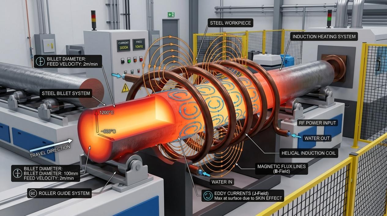
When engineers approach hot and warm working processes such as forging, forming, extrusion, and rolling, achieving optimal formability is the primary objective. Temperature dramatically affects the formability of metallic materials. Heating a workpiece entirely through its cross section to temperatures within the plastic deformation range creates the optimal thermal condition for subsequent shaping. According to established industrial documentation, induction mass heating is widely adopted because it provides a rapid, controllable, and repeatable method to achieve these target temperatures. Furthermore, metallic components subjected to hot and warm working demonstrate enhanced structural integrity, superior mechanical properties, and a more homogeneous grain structure. These shaped components typically exhibit reduced internal segregation, improved toughness, ductility, and elevated fatigue resistance compared to traditional cast materials. Fibrous grain structures developed after forging are particularly beneficial; when the grain flow is oriented perpendicular to the anticipated direction of crack propagation, these structures effectively impede crack development during service operations.
Induction mass heating applications encompass a vast array of workpiece sizes. For instance, billet diameters can range from small cross sections of 12.7 millimeters up to massive diameters of 210 millimeters or greater. The feed stock might consist of continuous cast metals, ingots, slabs, blooms, or powder metallurgy materials. The primary objective is to bring the component to the target temperature while maintaining strict uniformity across the diameter, along the length, and around the circumference.
Material Specifics: Steels, Stainless, and Superalloys
Hot and Warm Working of Carbon Steels
At hot forging temperatures, which typically range from 1100°C to 1300°C, and warm forging temperatures spanning 815°C to 1100°C, plain carbon steels become highly malleable. This temperature-dependent plasticity is governed primarily by the steel's composition and microstructural phase transformations. A critical engineering consideration is the normal variation in chemical composition within a single steel grade. Based on industry standards, the carbon content for typical plain carbon steels can vary by approximately 0.05 percent or more. This seemingly minor variation can shift the solidus temperature by over 70°C. Such deviations require the induction heating process recipe to maintain tight temperature control to prevent incipient melting or degradation of the microstructure.
High-Strength Low-Alloy (HSLA) Steels
Microalloyed or HSLA steels rely on minute additions of elements like vanadium, niobium, titanium, chromium, zirconium, copper, or nickel to enhance engineering properties without the need for extensive post-forging heat treatments. Vanadium and titanium carbonitrides precipitate during the thermal cycle to provide dispersive strengthening and grain refinement. Vanadium carbonitrides form at lower temperatures, whereas titanium carbonitrides form at higher temperatures and help limit grain growth. Though these steels offer hardness and fatigue resistance comparable to quenched and tempered grades, their electrothermal characteristics during heating are similar to plain carbon steels.
Stainless Steels and Superalloys
Induction heating of stainless steels and superalloys presents unique challenges. Austenitic stainless steels contain significant chromium for passivation and are nonmagnetic. According to fundamental metallurgical principles, austenitic stainless steels exhibit electrical resistivities that are three to four times higher than plain carbon steels at room temperature, and approximately 20 percent higher at forging temperatures. This higher resistivity, combined with lower magnetic permeability, results in a significantly greater current penetration depth. Paradoxically, while the induced heat penetrates deeper, stainless steels possess markedly lower thermal conductivities than carbon steels. This low thermal conductivity severely restricts the heat transfer from the surface to the core, complicating the effort to achieve cross-sectional temperature uniformity.
Superalloys, predominantly nickel-based formulations such as Inconel 600, 625, and 718, are heavily utilized in aerospace and petrochemical sectors for their high-temperature strength and oxidation resistance. Depending on the exact alloy, the melting range can be between 1260°C and 1415°C. Industrial guidelines strongly advise that the maximum permissible heating temperature remains at least 80°C to 120°C below the solidus temperature to prevent irreversible microstructural damage. The heating of these complex alloys requires highly controlled profiles, often targeting 950°C to 1200°C for forging applications, ensuring optimal deformation characteristics while suppressing grain coarsening.
Core Variables: Frequency, Power, Throughput, and Temperature Uniformity
The specification of frequency, power, and throughput is highly interdependent. Frequency selection is arguably the most critical parameter in induction mass heating. If the applied frequency is too low relative to the workpiece diameter, eddy current cancellation occurs in the core. This leads to extremely poor electrical efficiency and can completely prevent the workpiece from reaching the target temperature. A standard engineering rule of thumb dictates that the ratio of the workpiece diameter to the current penetration depth must be greater than four to avoid cancellation effects in solid cylinders.
Conversely, an excessively high frequency concentrates the induced eddy currents in a very fine surface skin layer. In this scenario, the core relies entirely on thermal conduction to heat up. This significantly prolongs the required heating time, leading to increased surface heat losses via radiation and convection, ultimately degrading the overall thermal efficiency of the induction heater.
In practical terms, the skin effect dictates that 86 percent of the induced power is concentrated within the current penetration depth. Therefore, ensuring surface-to-core temperature uniformity relies heavily on the careful management of power density and soak times. When power is applied, surface and average temperatures rise rapidly, while the core temperature lags. Once the power is turned off or reduced, the soaking stage begins, allowing thermal conduction to drive the surface heat into the cooler core. Advanced techniques such as power pulsing—applying short bursts of power followed by off periods—can reduce overall process times by over 25 percent while strictly maintaining allowable thermal gradients.
Note
Accelerated heating modes drive the surface temperature to the maximum permissible limit as quickly as possible to generate a steep thermal gradient that forces heat into the core. However, modified accelerated heating profiles must be employed for materials with low toughness, such as cast irons or as-cast high-carbon steels. Aggressive initial heating can induce massive thermal stresses, leading to devastating longitudinal and transverse cracking originating from microscopic stress risers like porosity, inclusions, or segregations.
Design Approaches and Selection Logic
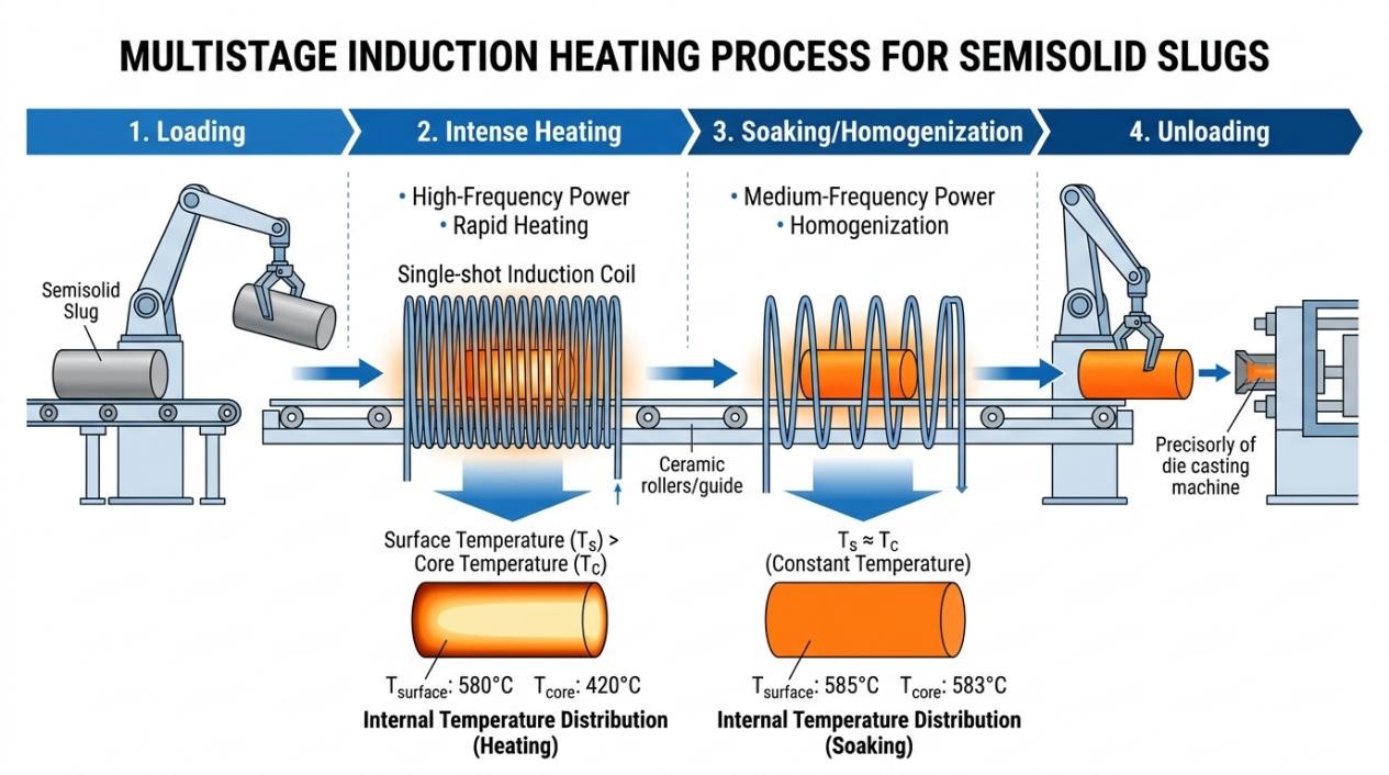
Based on operational throughput and material handling mechanics, engineers typically select from four fundamental heating modes. The static heating mode involves placing a single workpiece into a vertical or horizontal induction coil. A predetermined amount of power is applied over a fixed duration until thermal uniformity is reached, after which the part is ejected to the forming press. This approach is ideal for large, individual billets or specialized, lower-volume production.
Progressive multistage heating moves multiple billets sequentially through a single long coil or a series of multiple coils using pusher mechanisms, walking beams, or robotic indexing. This allows different stages of the coil line to apply different power densities, perfectly tuning the thermal profile as the part advances toward the exit.
Continuous heating relies on the uninterrupted, steady-state motion of continuous materials—such as wire, rod, tube, strip, or slab—through the inductor assembly. Finally, oscillating heating features a space-saving design where the workpiece moves back and forth within the coil to achieve uniformity without requiring an excessively long line footprint.
Quick Formula
Rough estimations for induction mass heating of carbon steel cylinders to forging temperatures can be calculated using established empirical formulas. The minimum required heat time in seconds can be approximated as 25 × (diameter in inches)². The minimum coil length in inches can be estimated by multiplying the desired production rate in pounds per hour by a factor of 0.03. These baseline figures are subsequently refined through intensive numerical modeling.
Handling, Line Layout Concepts, and Coil Design
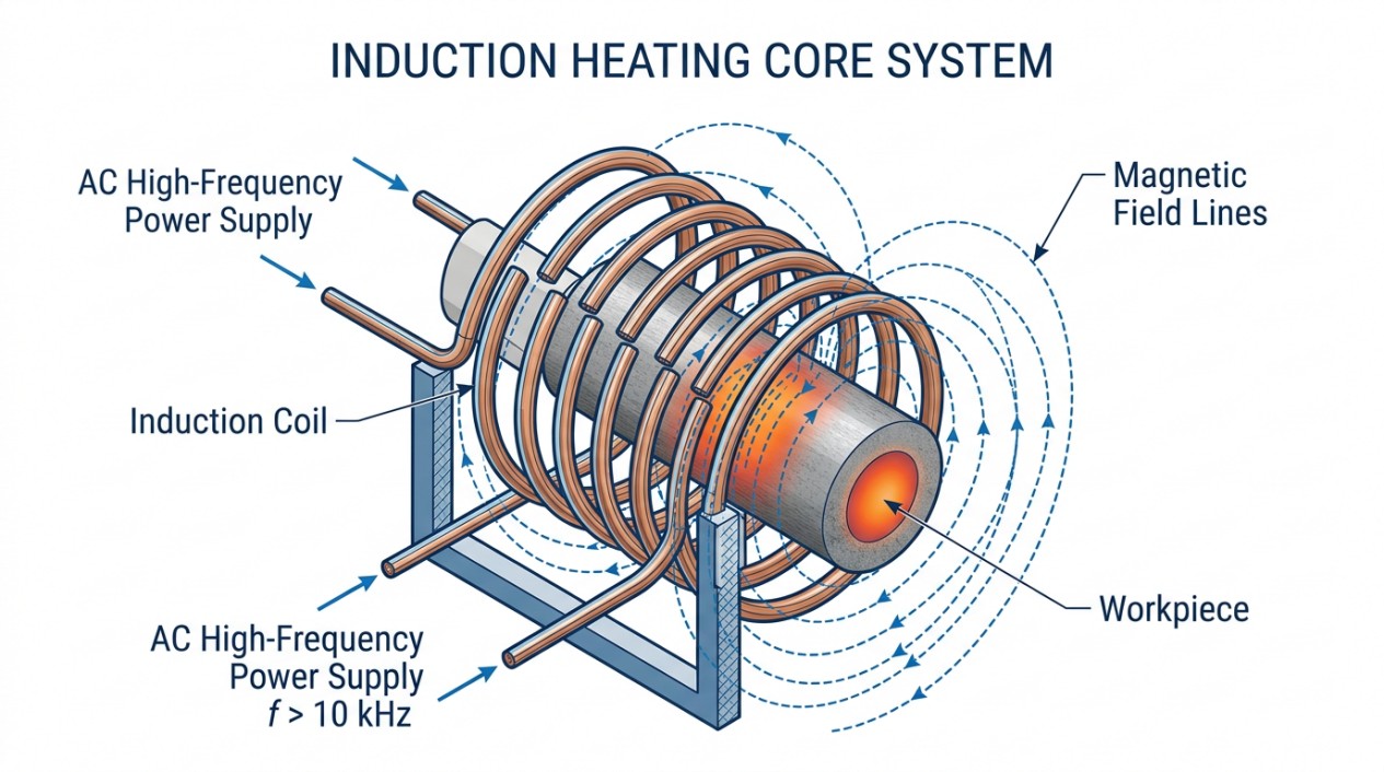
Solenoid multiturn coils are the standard configuration for induction mass heating, engineered to meet rigorous electrical, mechanical, and safety standards. To optimize electromagnetic coupling, the gap between the copper windings and the workpiece must be minimized. However, thermal management necessitates the insertion of protective refractory liners. These castable ceramics, sialon, or high-temperature cement liners—ranging from 6 millimeters to 38 millimeters in thickness—protect the copper from radiated heat but inherently decrease coil electrical efficiency by widening the coupling gap.
For internal material handling, water-cooled skid rails or solid skid plates run the length of the coil to support the weight of the moving billets. These rails are frequently fabricated from nonmagnetic stainless steel or nickel-based superalloy tubing with diameters between 4 and 12 millimeters. To combat severe mechanical wear, the contact surfaces are hard-faced using plasma or oxygen-acetylene torches to deposit wear-resistant coatings like Stellite or tungsten carbide. A persistent engineering challenge with skid rails is their heat sink effect; thermal conduction from the hot billet into the water-cooled rail can generate localized cold spots on the workpiece, degrading temperature uniformity.
The coil construction itself typically utilizes high-conductivity square, rectangular, or round copper tubing. The tubing wall thickness is scaled to the operating frequency, requiring a dimension greater than 1.6 times the current penetration depth in copper to prevent excessive kilowatt losses. At lower operating frequencies, the coil experiences significant electromagnetic vibration. Therefore, robust mechanical supports and rigid bracing are mandatory to prevent fatigue failure of the coil windings and the breakdown of the dielectric epoxy insulation separating the turns. The coil space factor, an indicator of how tightly the turns are wound, optimally ranges between 0.7 and 0.85.
Measurement, Control, and Process Optimization
Process control in induction mass heating relies on accurate measurement and responsive power modulation. Maintaining the surface-to-core temperature differential within safe limits requires sophisticated control algorithms that govern the power pulsing and acceleration modes. Pyrometry and thermal imaging are often integrated at critical locations along the coil line to monitor the real-time surface temperature of the billets. If the surface temperature approaches the critical threshold (typically 80°C to 120°C below the melting point), the control system must immediately throttle the inverter output to initiate a soaking phase.
For challenging materials with poor thermal conductivity, the control architecture must extend the transit time or increase the line length to facilitate sufficient thermal conduction into the core without overdriving the surface. Additionally, closed-loop control systems must monitor the inlet water temperatures and flow rates of the skid rails and copper windings to prevent catastrophic overheating caused by localized boiling or scale blockage in the cooling circuits.
Typical Pitfalls and Commissioning Checklist
Deploying an induction mass heating line exposes engineers to several recurring pitfalls. Incorrect frequency specification is a primary failure mode, resulting in either core cancellation or surface overheating. Another common issue is geometric mismatch—attempting to run square billets through round coil liners increases the air gap unevenly, severely degrading load matching and heating efficiency. Furthermore, aggressive heating of as-cast components without a modified acceleration profile routinely causes deep internal cracking. Mechanical degradation of skid rails due to excessive billet weight can crush the tubing, restricting water flow and leading to immediate rail burnout.
Essential Commissioning Checklist
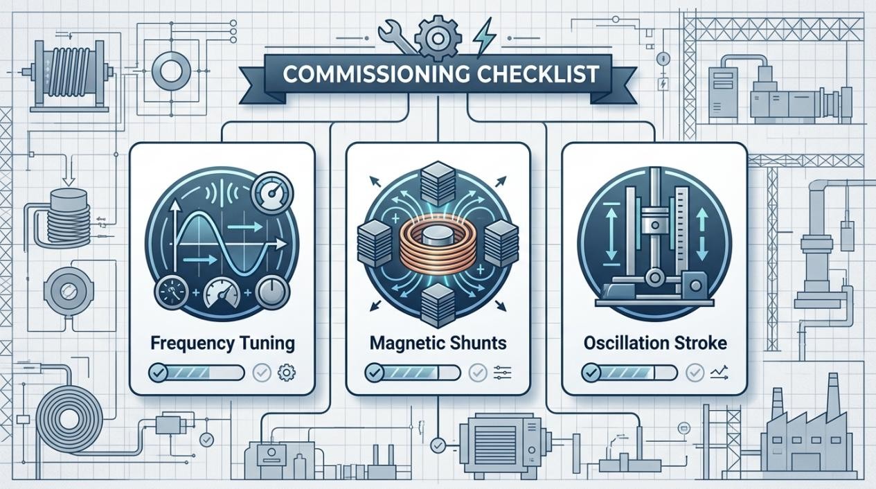
- Frequency Validation: Verify that the chosen frequency satisfies the ratio of workpiece diameter to current penetration depth (must be greater than four for solid cylinders).
- Material Integrity Audit: Ensure that incoming steel stock is properly characterized (wrought versus as-cast) to define the maximum allowable thermal gradient and prevent stress cracking.
- Refractory and Coil Gap Verification: Measure the space between the copper windings, the refractory liner, and the maximum billet size to confirm optimal electromagnetic coupling while maintaining thermal insulation.
- Skid Rail Inspection: Inspect the structural integrity and hard-face wear coating of the water-cooled skid rails. Confirm adequate water flow rates to prevent boiling and measure for any deflection under maximum billet load.
- Thermal Profile Tuning: Execute initial heating runs with instrumented billets to track the surface-to-core temperature differential. Adjust the power pulsing and soak cycle durations to eliminate localized cold spots near the skid rails.
- Cooling Circuit Flow Testing: Systematically test all independent coil cooling circuits. Verify that the copper tubing wall thickness exceeds 1.6 times the penetration depth in copper for the selected frequency.
- Vibration and Support Check: Especially critical in low-frequency systems, inspect the mechanical bracing and dielectric epoxy insulation on the end turns to ensure electromagnetic forces do not induce resonant vibration or fatigue.
FAQ about Induction Mass Heating
Q: Why is frequency selection so critical in induction mass heating?
Frequency directly affects heating efficiency and uniformity. If the frequency is too low, eddy current cancellation occurs in the workpiece core, preventing it from reaching target temperature. If too high, power concentrates only at the surface, requiring excessive time for heat to conduct inward. The engineering rule is that the workpiece diameter-to-penetration depth ratio must exceed four to avoid cancellation effects in solid cylinders.
Q: Why are stainless steels and superalloys more challenging to heat than carbon steels?
Austenitic stainless steels have electrical resistivity 3–4 times higher than carbon steels and significantly lower thermal conductivity. This means heat penetrates deeper but transfers much slower from surface to core, making uniform heating difficult. Superalloys require even tighter control—heating temperatures must stay 80–120°C below the melting point to prevent irreversible microstructural damage.
Q: What causes cold spots on heated billets, and how can they be prevented?
Cold spots typically form where the hot billet contacts water-cooled skid rails that support it during heating. Heat conducts from the workpiece into these rails, creating localized cool zones. Prevention strategies include optimizing rail design, applying wear-resistant coatings, adjusting power pulsing profiles, and using thermal imaging to monitor and compensate for these effects through control system adjustments.
Conclusion: Induction Mass Heating Fundamentals
Following these systematic design and commissioning protocols ensures the safe, efficient, and highly repeatable operation of induction mass heating systems across various demanding metalworking applications. Consistent attention to metallurgical variables, electrothermal dynamics, and robust mechanical design remains the foundation of a successful deployment.
Keep Learning
Induction Billet Heating: How to Achieve Uniform Heating
Induction billet heating prepares metal for forging, extrusion, or rolling by generating heat inside the workpiece. For steel billets, reaching the required exit temperature is only part of the task: the temperature distribution from surface to core and along the billet must also suit the forming process. Uniformity depends on how frequency, coil geometry, heat transfer, power distribution, and billet movement work together. This guide focuses on through-heating steel billets, particularly in progress......
How to Upgrade a 3D Printer Heated Bed with a Silicone Heater
If your 3D printer heated bed takes too long to reach temperature, develops uneven heating, or struggles to maintain a stable surface temperature, a silicone heater can be a practical upgrade. Faster warm-up and more uniform heat can improve first-layer consistency and reduce temperature-related printing issues. This guide explains how to identify when a heated-bed upgrade is needed, choose a suitable silicone heater, install it safely, and verify the results. Quick Answer A silicone heater can be a s......
How Graphene and MXene Flake Sensors Detect Force
Key Takeaways Flake networks sense force through microstructural change: Graphene and MXene coatings distribute conduction across overlapping platelets whose contacts shift under stretch or pressure, producing measurable resistance changes. Three mechanisms compete: Crack propagation, flake slippage, and quantum tunnelling each dominate at different deformation levels, giving many sensors multiple sensitivity regions rather than one uniform response. The substrate is an active partner: Elastomers, tex......
Conductive 2D Coatings Are a Matching Problem, Not a Miracle Ink
Key Takeaways Ink is a system, not a material: Conductivity depends on the combined effect of flake chemistry, solvent, additives, substrate, coating method, and post-processing—not on the 2D filler alone. Three carbon routes carry different trade-offs: GNPs demand dispersion engineering, GO shifts effort to a reduction step, and MXenes move the bottleneck to synthesis, storage, and oxidation control. Substrate geometry drives method selection: Spray and blade coating suit flat sheets; dip coating nat......
Graphene Heat Spreader Design: Layers and Interfaces
Key Takeaways Conductivity alone is not enough: A record thermal-conductivity value does not guarantee a cooler chip. Effective thickness, interface resistance, hot-spot geometry, and heat-sink connections all belong to the same thermal path. Few-layer graphene can outperform a single layer in practice: A few-layer sheet provides a larger heat-flow cross section and better tolerates transfer, embedding, and defects, even though its intrinsic conductivity is lower. Interface resistance is the bottlenec......
How Graphene Heat Spreaders Cool SOI Chip Hot Spots
Key Takeaways Buried oxide is a thermal bottleneck: SOI's insulating layer improves electrical isolation but traps heat near transistor channels, creating dangerous hot spots that package-level cooling alone cannot fix. Graphene enables lateral heat routing: Placing graphene or few-layer graphene beneath the buried oxide adds a high-conductivity sideways path, redistributing hot-spot energy toward dedicated sinks without removing any heat itself. Multi-source chips benefit most: Finite-element modelin......