Advanced Induction Joining and Assembly: From Adhesive Bonding to Motor Rotor Integration
11 min
- 1. Induction Bonding: Joining Dissimilar Materials
- 2. Induction Cap Sealing: Hermetic Packaging at Scale
- 3. Shrink Fitting: Mechanical Bonding through Thermal Expansion
- 4. Motor Rotor Heating: Optimizing Electric Motor Assembly
- 5. Unified Commissioning Checklist for Induction Assembly
- FAQ about Induction Joining and Assembly
Key Takeaways
Induction Bonding: Uses heat transferred from an induction-heated metallic part to cure adhesives, enabling strong joints between dissimilar materials like plastics, ceramics, and metals.
Cap Sealing: A non-contact induction process that heats an aluminum foil liner inside bottle caps to create hermetic, tamper-evident seals at high line speeds.
Shrink Fitting: Exploits thermal expansion to create high-strength interference fits without fasteners or fillers, and is often reversible for maintenance purposes.
Motor Rotor Heating: Induction replaces furnace heating for rotor shaft insertion, reducing floor space by up to 95% and cutting cycle times from hours to seconds.
Commissioning: A four-point checklist covering power validation, fixturing, thermal profiling, and destructive testing ensures reliable production readiness for any induction assembly process.
In modern manufacturing, the precision and speed of assembly often dictate the overall competitiveness of a production line. Induction heating has emerged as a cornerstone technology for joining and assembly, offering a non-contact, highly repeatable method for integrating components across diverse material sets. Unlike traditional furnace or flame-based methods, induction allows for localized heat application, rapid cycle times, and seamless integration into automated workflows. This post examines four critical induction-based assembly applications—adhesive bonding, cap sealing, shrink fitting, and motor rotor heating—and provides a unified framework for commissioning these systems in a production environment.
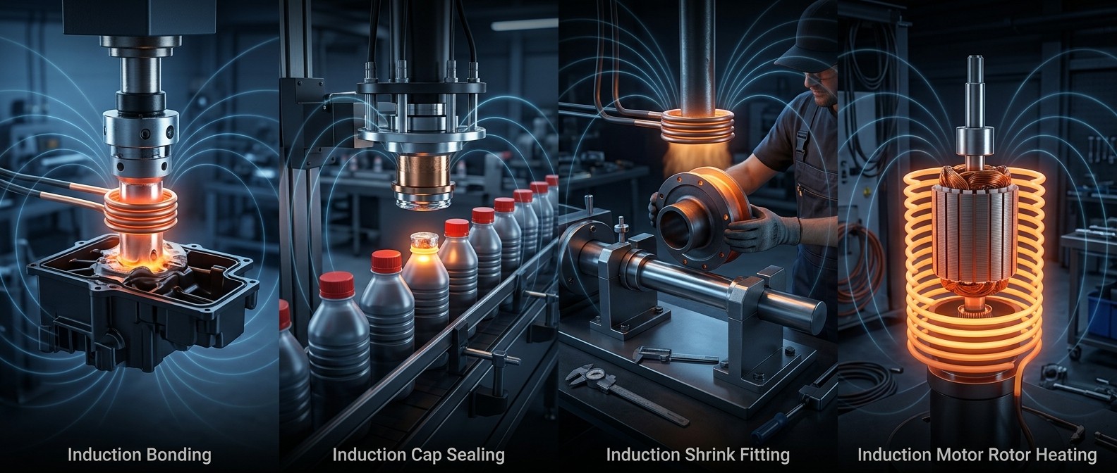
Overview of induction applications: Bonding, Cap Sealing, Shrink Fitting, and Motor Rotor Heating.
1. Induction Bonding: Joining Dissimilar Materials
Induction bonding is a universal joining technique where an adhesive material provides the bond between two or more components. A significant advantage of this method is its ability to join nonmetallic materials such as plastics, ceramics, glass, and composites to metallic structures. This is particularly valuable in industries like automotive and aerospace, where weight reduction is achieved by substituting heavy metallic parts with lighter alternatives. Since adhesives are typically not electrically conductive, the bonding effect relies on thermal conduction from an induction-heated metallic component in contact with the adhesive. In many cases, applied pressure is also required to ensure a robust interface during the curing or softening phase.
Principles and Equipment
The process utilizes either thermoplastic or thermosetting adhesives. Thermoplastic adhesives soften when heated and harden upon cooling, while thermosetting adhesives undergo polymerization—a chemical reaction accelerated by heat. Induction is effective for both, providing the rapid temperature rise needed to initiate the bond. Typical equipment includes a power supply (often 5 to 10 kW), an induction heating coil tailored to the joint geometry, and a fixture to maintain part alignment. For example, a brake pedal support system might use a 30 kHz power supply to heat stake a rubber gasket to a metal frame in just 4 seconds.
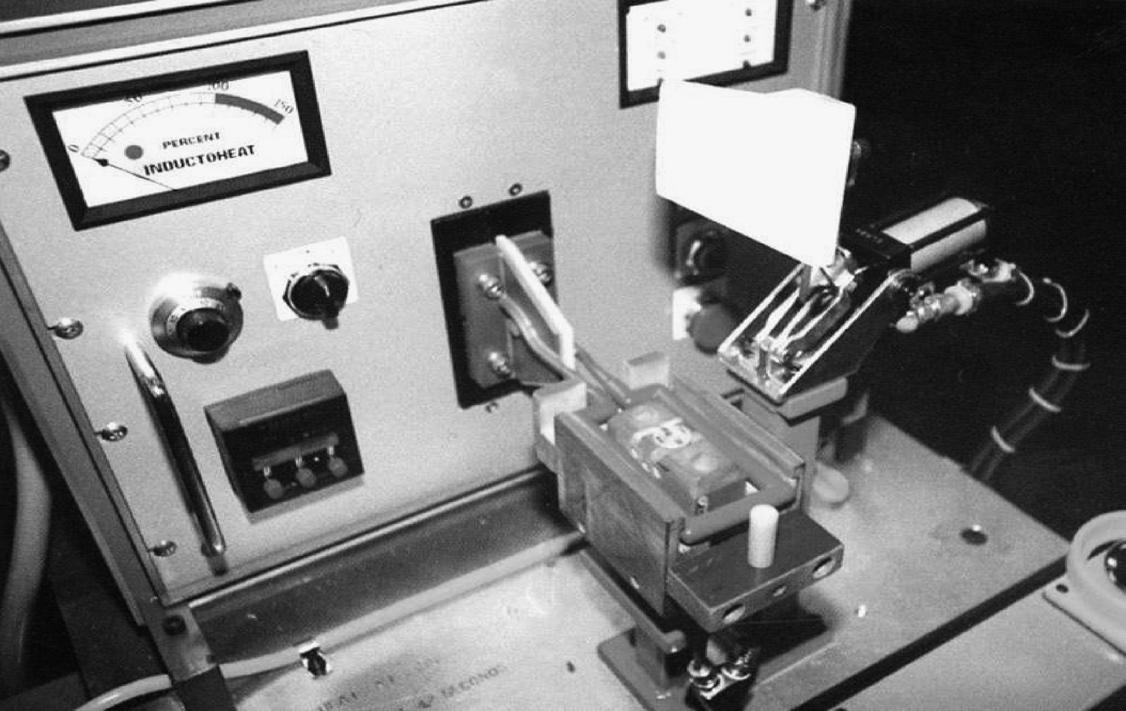
Induction bonding system used for joining rubber gaskets to metal supports.
Process Controls and Failure Modes
Because bonding is a low-temperature application (typically below 230°C), power requirements are modest. However, frequency and power density must be optimized based on the component size and material. Failure to control the temperature accurately can lead to several issues. Overheating may cause thermal degradation of nonmetallic components, such as rubber becoming brittle or plastic melting beyond the joint area. Conversely, insufficient heating leads to incomplete curing of thermosetting adhesives, resulting in low joint strength and potential assembly failure during subsequent handling. Typical failure modes also include uneven stress distribution if the coil design does not provide uniform heating across the bond line.
2. Induction Cap Sealing: Hermetic Packaging at Scale
Induction cap sealing is a specialized variation of bonding used primarily in the packaging industry to create hermetic, tamper-evident seals on containers. A foil disk, usually aluminum with a heat-seal coating, is placed inside a plastic or glass bottle cap. As the capped bottle moves along a conveyor, it passes under an induction sealing head. The electromagnetic field penetrates the non-conductive cap and induces eddy currents in the foil, heating it almost instantaneously. This heat activates the coating, which then bonds to the lip of the container as it cools. This non-contact process is essential for maintaining product integrity in food, pharmaceutical, and chemical industries.
Equipment and Fixturing
The primary hardware consists of a conveyor-mounted induction power supply and a specialized sealing head designed to distribute the field evenly across the cap's surface. Modern lines often include monitoring systems, such as a Cap Inspector, to verify the presence of the foil and the correct seating of the cap. The setup is remarkably efficient because it requires no physical contact, allowing for extremely high line speeds without the mechanical wear associated with thermal conduction heaters.
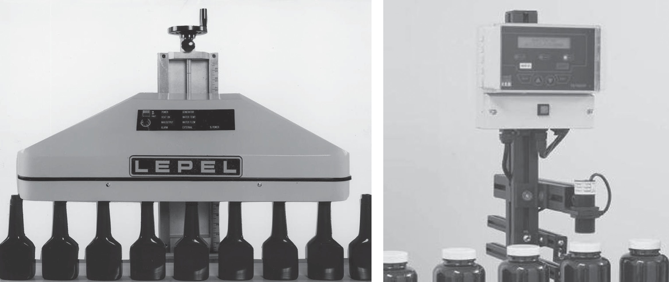
High-speed induction cap sealing head and line monitor system.
Process Window and Typical Failures
The process window for cap sealing is narrow. If the induction field is too strong or the conveyor speed is too slow, the foil can overheat, causing the liner to char or the plastic bottle lip to deform, which destroys the seal's integrity. If the power is too low, the bond will be incomplete, leading to leaks or loss of the tamper-evident feature. Common failure modes include "leakers" caused by tilted caps, which create an uneven air gap between the foil and the sealing head, resulting in non-uniform heating. Regular inspection of the cap position and foil presence is a critical control measure.
3. Shrink Fitting: Mechanical Bonding through Thermal Expansion
Shrink fitting exploits the thermal expansion and contraction properties of metals to join components without fillers or fasteners. An external component, such as a gear, bearing, or steering knuckle, is heated to expand its bore. The internal component (a shaft or spindle) is then inserted. As the assembly cools to room temperature, the external part contracts, creating a high-strength mechanical interference fit. This process is often reversible; by reheating the external component, parts can be disassembled for maintenance without the permanent deformation that might occur with high-pressure press fitting.
Equipment and Fixturing
For shrink fitting, the entire part or a significant annular region must be heated. This requires low power density and relatively low frequencies (from line frequency up to 10 kHz) to ensure deep, uniform heat penetration. Common inductors include solenoid coils or C-core type inductors. Automated systems often use rotary-indexing units with multiple stations for preheat, final heat, and press-insertion. For instance, truck steering knuckles might be heated to 370°C using C-core inductors powered by line frequency, followed by a soak period to ensure temperature uniformity before the spindle is inserted.
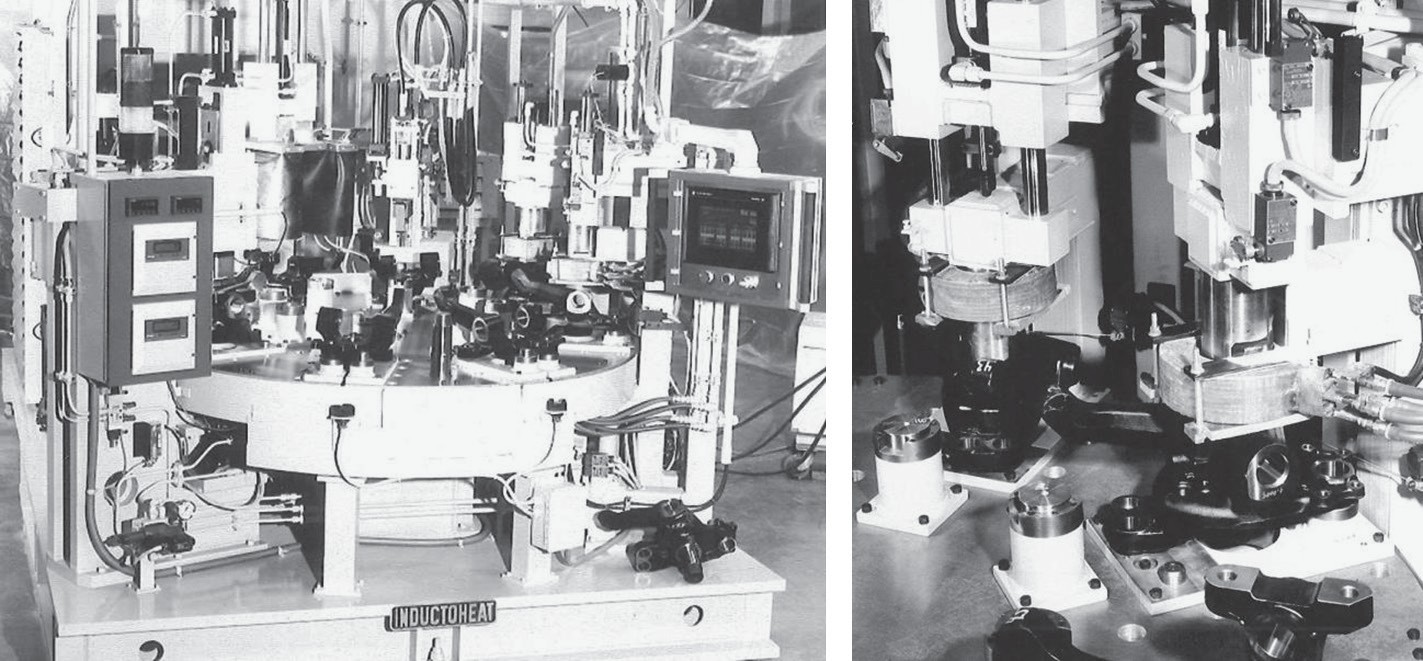
Automated rotary-indexing system for induction shrink-fitting of steering knuckles.
Process Controls and Failure Modes
Temperature control is the most critical parameter in shrink fitting. If the part is under-heated, the bore will not expand sufficiently, causing the parts to seize during assembly and potentially damaging both components. Overheating, on the other hand, can alter the metallurgical properties of the steel, such as reducing its hardness or inducing unwanted distortion. Optical pyrometers are typically employed to monitor part temperature in real-time. A common failure mode in automated lines is the "short hit," where a part is indexed before reaching the target temperature, leading to assembly jams.
4. Motor Rotor Heating: Optimizing Electric Motor Assembly
In electric motor manufacturing, induction heating is used to heat rotors to facilitate the insertion of motor shafts. This application is a specific form of shrink fitting but involves additional complexities due to the composite nature of the rotor (laminations and die-cast aluminum). Beyond shaft insertion, induction is used for die-cast bond breaking to improve motor efficiency, lamination bluing for rust prevention, and epoxy curing. Transitioning from traditional ovens to induction has allowed manufacturers to reduce floor space by up to 95% and cut heating times from hours to minutes.
Equipment and Fixturing
Rotor heaters typically use solenoid-type encapsulated coils. Systems can be in-line with adjustable magazines and electric actuators to handle various rotor diameters and stack heights. High-power systems (e.g., 200 kW at 1 kHz) can heat rotors to temperatures of 425°C to 485°C at rates as fast as one part every 7 seconds. The use of a PLC and HMI allows for rapid changeover between different part "recipes," ensuring that the correct energy is delivered to each specific rotor design.
Process Window and Quality Impacts
The process window must account for the narrow clearance between the rotor and stator, which typically ranges from 0.05 mm to 0.08 mm. Unlike furnace heating, which can cause aluminum blistering due to escaping gases, induction provides a controlled environment that minimizes these defects. The primary quality metric is the consistent expansion of the bore. Improper heating can lead to shaft misalignment or insufficient grip, resulting in RPM variation or mechanical failure in the field. Quenching after heating has also been shown to reduce RPM variation between motors, enhancing overall product quality.
5. Unified Commissioning Checklist for Induction Assembly
Successful implementation of any induction joining or assembly process requires a rigorous commissioning phase. While the specific temperatures and frequencies vary, the underlying engineering principles remain consistent. The following checklist provides a unified framework for engineers to validate their induction systems before full-scale production begins.
-
Power Supply and Coil Validation
Verify that the power supply frequency (kHz) and power rating (kW) match the process requirements for penetration depth and cycle time. Inspect the coil for proper alignment and centering relative to the workpiece to ensure uniform heating. Check all water-cooling circuits for leaks and ensure flow rates meet the manufacturer's specifications for the coil and power supply.
-
Fixturing and Alignment
Confirm that the fixture material is non-conductive (e.g., ceramic or specialized plastic) in areas where it enters the induction field to prevent parasitic heating. Validate the repeatability of part positioning; even small air-gap variations can significantly impact heat distribution. Ensure that clamping pressure (for bonding) or insertion force (for shrink fitting) is calibrated and consistent across cycles.
-
Thermal Profile and Control
Use thermal imaging or multi-point thermocouples during the initial setup to map the temperature distribution across the joint area. Calibrate optical pyrometers or IR sensors against a known reference to ensure accurate temperature monitoring. Establish the "Upper" and "Lower" limit alarms in the PLC to automatically reject parts that fall outside the validated process window.
-
Quality and Integrity Testing
Perform destructive testing (e.g., peel tests for bonding, pull tests for shrink fitting) on the first run of parts to verify joint strength. For sealing applications, conduct vacuum or pressure tests to confirm hermetic integrity. Audit the process for secondary effects, such as distortion, metallurgical changes, or thermal damage to adjacent components.
FAQ about Induction Joining and Assembly
Q: What makes induction bonding suitable for joining dissimilar materials like plastics to metals?
Induction bonding uses adhesives (thermoplastic or thermosetting) as the joining medium, allowing nonmetallic materials to bond to metal components. The induction field heats the metallic part, which then transfers heat to the adhesive through conduction. This enables lightweight materials like plastics, ceramics, or composites to replace heavier metal parts in automotive and aerospace applications while maintaining strong joints.
Q: How does induction cap sealing create tamper-evident seals without touching the container?
Induction cap sealing works by generating an electromagnetic field that passes through the non-conductive cap and induces eddy currents in the aluminum foil liner inside. This heats the foil almost instantly, activating a heat-seal coating that bonds to the container lip. The non-contact process allows for high-speed production lines while creating hermetic, tamper-evident seals for food, pharmaceutical, and chemical packaging.
Q: What are the main advantages of using induction heating for motor rotor assembly compared to traditional ovens?
Induction heating reduces floor space by up to 95% and cuts heating times from hours to minutes. It provides precise, localized heating that prevents defects like aluminum blistering common in furnace heating. The controlled thermal expansion allows accurate shaft insertion with minimal clearance (0.05–0.08 mm), and the rapid process integrates easily into automated production lines with quick changeover between different rotor designs.
Conclusion: Induction Joining and Assembly Guide
By standardizing these controls across bonding, sealing, and fitting operations, engineers can leverage the full potential of induction technology to create faster, leaner, and more reliable assembly lines. The transition from manual or furnace-based assembly to automated induction processes represents not just a change in equipment, but a fundamental improvement in manufacturing precision.
Keep Learning
How to Upgrade a 3D Printer Heated Bed with a Silicone Heater
If your 3D printer heated bed takes too long to reach temperature, develops uneven heating, or struggles to maintain a stable surface temperature, a silicone heater can be a practical upgrade. Faster warm-up and more uniform heat can improve first-layer consistency and reduce temperature-related printing issues. This guide explains how to identify when a heated-bed upgrade is needed, choose a suitable silicone heater, install it safely, and verify the results. Quick Answer A silicone heater can be a s......
How Graphene and MXene Flake Sensors Detect Force
Key Takeaways Flake networks sense force through microstructural change: Graphene and MXene coatings distribute conduction across overlapping platelets whose contacts shift under stretch or pressure, producing measurable resistance changes. Three mechanisms compete: Crack propagation, flake slippage, and quantum tunnelling each dominate at different deformation levels, giving many sensors multiple sensitivity regions rather than one uniform response. The substrate is an active partner: Elastomers, tex......
Conductive 2D Coatings Are a Matching Problem, Not a Miracle Ink
Key Takeaways Ink is a system, not a material: Conductivity depends on the combined effect of flake chemistry, solvent, additives, substrate, coating method, and post-processing—not on the 2D filler alone. Three carbon routes carry different trade-offs: GNPs demand dispersion engineering, GO shifts effort to a reduction step, and MXenes move the bottleneck to synthesis, storage, and oxidation control. Substrate geometry drives method selection: Spray and blade coating suit flat sheets; dip coating nat......
Graphene Heat Spreader Design: Layers and Interfaces
Key Takeaways Conductivity alone is not enough: A record thermal-conductivity value does not guarantee a cooler chip. Effective thickness, interface resistance, hot-spot geometry, and heat-sink connections all belong to the same thermal path. Few-layer graphene can outperform a single layer in practice: A few-layer sheet provides a larger heat-flow cross section and better tolerates transfer, embedding, and defects, even though its intrinsic conductivity is lower. Interface resistance is the bottlenec......
How Graphene Heat Spreaders Cool SOI Chip Hot Spots
Key Takeaways Buried oxide is a thermal bottleneck: SOI's insulating layer improves electrical isolation but traps heat near transistor channels, creating dangerous hot spots that package-level cooling alone cannot fix. Graphene enables lateral heat routing: Placing graphene or few-layer graphene beneath the buried oxide adds a high-conductivity sideways path, redistributing hot-spot energy toward dedicated sinks without removing any heat itself. Multi-source chips benefit most: Finite-element modelin......
Graphene Heaters Look Brilliant in the Lab. Can They Survive the Real World?
Key Takeaways Undoped graphene simplifies reliability: By avoiding chemical dopants that can migrate or degrade, undoped CVD graphene removes one failure route — though it starts with higher sheet resistance than doped alternatives. Layer stacking is a design trade-off: Each added graphene layer lowers resistance and voltage requirements but also reduces optical transmission and introduces potential transfer defects such as wrinkles and polymer residue. Durability is the real barrier: After one year i......