
Induction Heating for Tubes and Pipes: Uniform Heat Around a Geometry That Loves to Drift
10 min
- Fundamentals of Induction Heating for Tubular Products
- Challenges in Uniform Heating and Resonant Phenomena
- Coil Design and In-Line Induction Heating Systems
- Applications in Tube and Pipe Processing
- Practical Considerations and Process Optimization
- Summary Checklist: Induction Heating for Tubes and Pipes
- FAQ about Induction Heating for Tubes and Pipes
Key Takeaways
Hollow geometry matters: Tubes and pipes require lower induction frequencies than solid cylinders because eddy currents flow on both inner and outer surfaces, demanding skin depth greater than wall thickness for uniform heating.
Frequency is the #1 design lever: Optimal frequency selection can improve electrical efficiency by 10–16%, reduce heating time, and lower equipment costs—but must also avoid structural resonant frequencies that cause hazardous noise.
Coil and system design drive throughput: Multi-coil in-line arrangements enable continuous processing for through-hardening, bright annealing, and high-speed copper tube annealing at speeds up to 500 m/min.
Applications span the full spectrum: From selective weld stress relieving and brazing to large-pipe coating preheating and galvanizing, induction heating provides precise, contactless solutions across industries.
Fundamentals of Induction Heating for Tubular Products
Induction heating relies on electromagnetic fields to induce eddy currents within a conductive material, generating heat internally without direct contact. While the principle remains consistent, the hollow geometry of tubes and pipes introduces complexities in current distribution and heat penetration.
Differences Between Solid and Hollow Cylinders
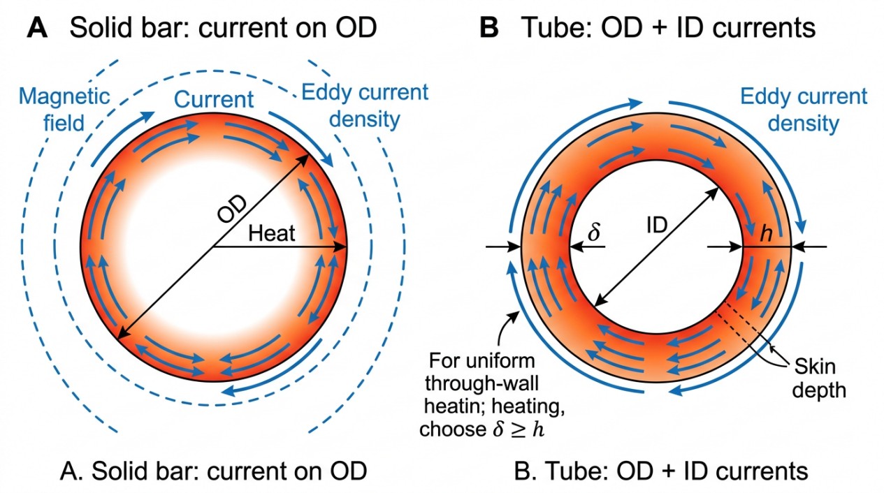
In solid cylinders, eddy currents primarily flow near the outer surface due to the skin effect, with negligible current in the core. For hollow cylinders, eddy currents can flow on both the outer diameter (O.D.) and inner diameter (I.D.) surfaces. This dual-surface current flow affects the heating profile and coil efficiency.
The coil efficiency—the ratio of power effectively transferred to the workpiece versus power supplied—is influenced by:
- Ratio of coil inner diameter (I.D.) to tube O.D.
- Tube wall thickness
- Electrical and magnetic properties of the tube material
- Coil length
- Operating frequency
Among these, frequency selection is the most critical factor affecting coil efficiency and heating uniformity.
Skin Depth and Frequency Selection
Skin depth (δ) is the effective penetration depth of induced currents and depends on frequency, electrical resistivity, and magnetic permeability of the material. For solid cylinders, optimal coil efficiency occurs when the ratio O.D./δ exceeds approximately 4. If the frequency is too low (O.D./δ < 3.2), eddy current cancellation reduces efficiency dramatically.
For tubular products, the optimal frequency shifts to lower values compared to solid cylinders. This is because the skin depth should be larger than the tube wall thickness to allow uniform heating through the wall. Frequencies typically lie between two characteristic frequencies (F4 and F2), lower than those for solid bars (between F1 and F2). Using lower frequencies can improve electrical efficiency by 10–16% or more, reduce bus bar losses, shorten heating times, and lower power supply costs.
Estimating Optimal Frequency
Simplified formulas provide quick estimates of optimal frequency for electromagnetically long solenoid-type inductors:
Quick Formula (Imperial Units)
$$f = \frac{34.6 \times \rho}{A_{m} \times h} \text{ (Hz)}$$
where:
- $\rho$ = electrical resistivity of the metal (μΩ·in.)
- $A_{m}$ = average diameter = (Tube O.D. – wall thickness) (in)
- $h$ = wall thickness (in)
Quick Formula (SI Units)
$$f = \frac{8.65 \times \rho \times 10^{5}}{A_{m} \times h} \text{ (Hz)}$$
where $\rho$ is in Ω·m, and $A_{m}$, $h$ are in meters.
Short coils or electromagnetically short inductors typically require higher frequencies than these estimates.
Challenges in Uniform Heating and Resonant Phenomena
Current Density Distribution in Tube Walls
The distribution of induced current density across the tube wall thickness is frequency-dependent. At higher frequencies, currents concentrate near the surfaces, while at lower frequencies, currents penetrate deeper, promoting uniform heating.
A subtle phenomenon can occur when a highly permeable magnetic flux concentrator is placed inside the tube. Under conditions where skin depth exceeds wall thickness, the current density distribution can become U-shaped, with peaks near both the inner and outer surfaces. The magnetic permeability ($\mu$) of the flux concentrator and the air gap between it and the tube I.D. significantly influence this distribution.
Understanding these effects is essential for optimizing coil design and heating uniformity, especially in specialized applications.
Structural Resonant Frequencies and Audible Noise
Tubes and pipes behave like musical instruments with distinct structural resonant frequencies (SRF) determined by their diameter, wall thickness, length, and material properties. When the induction heating frequency approaches the SRF, the tube can amplify vibrations, producing audible noise that may exceed safe levels.
This noise is not only a nuisance but also a potential health hazard for workers exposed over long periods. The unpleasantness of noise depends on both its magnitude and frequency; for example, low-frequency noise (e.g., 50 Hz) may be louder but less irritating than higher-frequency noise (~1 kHz).
Noise Mitigation Tip
Measure the SRF of tubes by mechanical excitation (e.g., tapping with a hammer) and select induction frequencies sufficiently distant from these resonances. For instance, if the SRF is 300 Hz, operating at 6 kHz reduces noise, whereas if the SRF is 5 kHz, 6 kHz operation may exacerbate it.
Coil Design and In-Line Induction Heating Systems
Coil Arrangements and Efficiency
Coil design for tube and pipe heating must accommodate the geometry and process requirements. Common coil types include:
- Solenoid coils for through-heating long tubes
- Short coils for localized or selective heating
- Multi-coil arrangements for staged heating and quenching
The coil I.D. must be carefully matched to the tube O.D. to maximize magnetic coupling and minimize leakage flux. Coil length affects the heated volume and power density; shorter coils heat smaller volumes faster but may cause temperature gradients.
Continuous In-Line Heating Systems
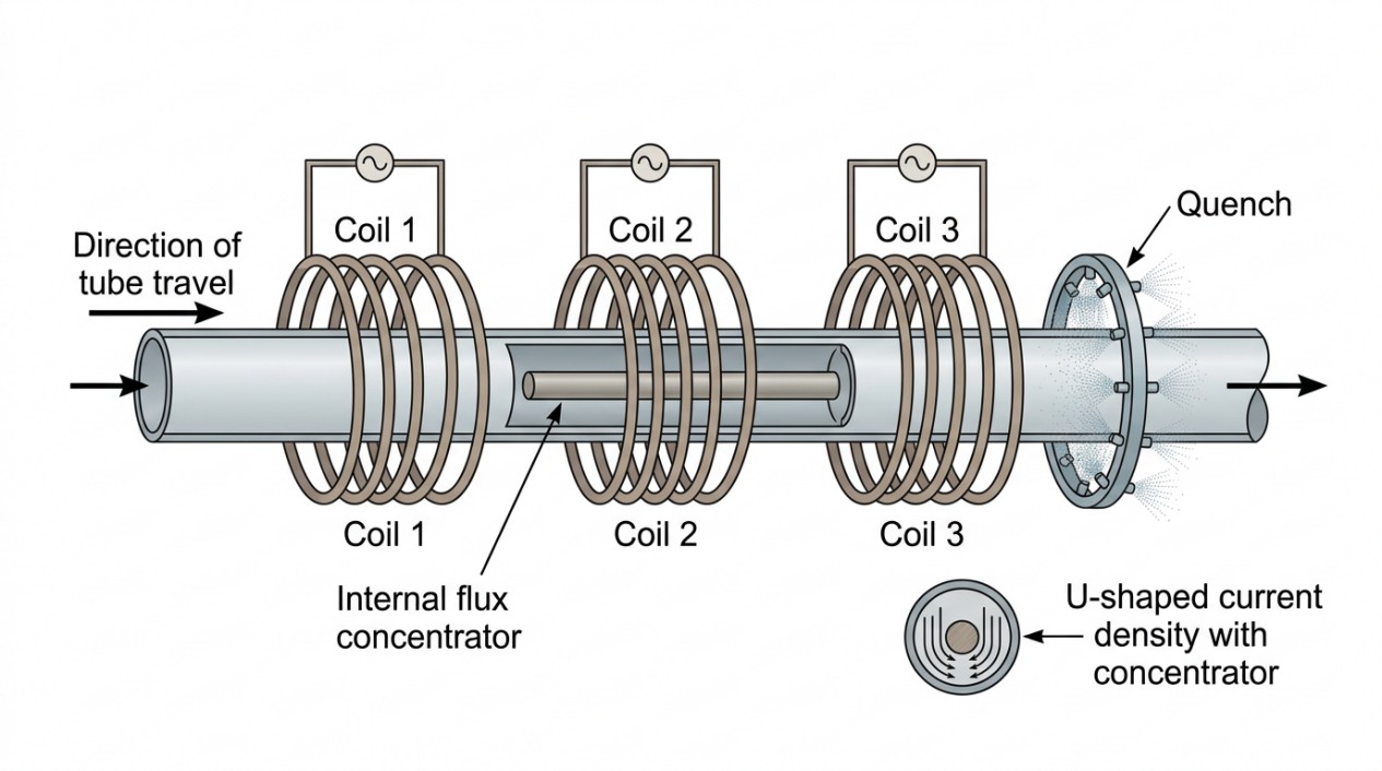
For high-volume production, continuous in-line induction heating systems are widely used. These systems often consist of multiple coils arranged sequentially to provide controlled heating profiles, followed by quenching or cooling zones.
Example: Induction Through Hardening of Carbon Steel Tubes
| Parameter | Value |
|---|---|
| Tube O.D. | 127 mm |
| Wall thickness | 12.7 mm |
| Line speed | 3 tons/hour |
| Frequency | 3 kHz |
| Configuration | Three in-line coils followed by a water spray quench |
Such systems enable precise control of heating rates and temperatures to achieve desired microstructures and mechanical properties.
Applications in Tube and Pipe Processing
Gas Quench Bright Annealing of Stainless Steel Tubes
Stainless steel tubes used in decorative and food processing applications require bright annealing to maintain surface quality. Induction heating raises the tube temperature to 1100–1150°C, followed by a long hydrogen-nitrogen gas quench tunnel.
Key considerations include:
- Purging oxygen with nitrogen before introducing hydrogen to prevent explosions
- Maintaining positive pressure in the quench tunnel to avoid contamination
- Ensuring tube temperature falls below ~300°C upon exit to prevent oxidation and tarnishing
- Using a holding zone between heating and quenching to stabilize temperature and microstructure
High-Speed Annealing of Copper Tubes
Copper tubing for plumbing, refrigeration, and industrial machinery demands precise annealing for dimensional accuracy, grain structure, and surface cleanliness.
Advantages of Induction Annealing for Copper Tubes
- Reduced equipment and operating costs
- Higher productivity with continuous processing
- Elimination of mechanical damage during handling
Typical process steps:
-
Induction Heating
Heat to annealing temperature (~700°C for phosphorous-deoxidized copper)
-
Holding/Dwell Zone
Allow recrystallization to occur at controlled temperature
-
Rapid Water Quench
Cool to handling temperature quickly
Automatic tension control systems maintain tube integrity at line speeds of 200–500 m/min, preventing marking and jamming.
Selective Heating Applications for Tubes and Pipes
Induction heating excels at localized heating, enabling selective processes such as:
- Stress relieving of welds and bends
- Brazing and soldering joints
- Tube parting and bending
- Surface coating preparation and curing
Large Pipe Heating for Coating Applications
Pipes for oil and gas lines often require preheating before applying protective coatings such as polyethylene or metallic layers.
Induction coils for these applications are typically large, robust, and mounted on movable frames or cranes for positioning. Coils are designed to accommodate multiple pipe sizes, with adjustable length and power to optimize heating uniformity.
Metallic and Nonmetallic Coatings
Metallic coatings: Galvanizing deposits zinc or zinc alloy layers on steel tubes to improve corrosion resistance and abrasion protection.
Nonmetallic coatings: Primers, paints, epoxies, polymers, and heat-cured powders are applied following induction preheating to ensure adhesion and curing.
Practical Considerations and Process Optimization
1Frequency Selection Trade-Offs
- Lower frequencies improve coil efficiency and reduce power supply costs but may increase audible noise due to resonance.
- Higher frequencies allow shorter coils and finer heating control but increase power losses and equipment costs.
- Frequency must be selected considering tube dimensions, material properties, line speed, and noise constraints.
2Coil Length and Power Density
- Longer coils provide more uniform heating but require higher power and may increase equipment size.
- Shorter coils enable rapid localized heating but risk temperature gradients and thermal stresses.
3Flux Concentrators and Magnetic Circuit Design
- Internal magnetic flux concentrators can enhance heating efficiency by focusing magnetic fields.
- Their permeability and positioning affect current distribution and heating uniformity.
- Computer modeling is essential to optimize these parameters.
4Noise Mitigation Strategies
- Measure structural resonant frequencies of tubes before process design.
- Select induction frequencies away from SRF to minimize vibration and noise.
- Employ sound dampening and worker hearing protection as necessary.
Summary Checklist: Induction Heating for Tubes and Pipes
- Understand tube geometry: Hollow structure requires different frequency and coil design than solid cylinders.
- Optimize frequency: Select frequency so skin depth exceeds wall thickness for uniform heating and high coil efficiency.
- Design coils carefully: Match coil I.D. to tube O.D., consider coil length for desired heating profile.
- Account for resonant vibrations: Measure tube SRF and avoid frequencies that cause excessive noise and vibration.
- Use flux concentrators judiciously: Internal magnetic flux concentrators can improve heating but require precise design.
- Implement continuous in-line systems: Multi-coil arrangements enable controlled heating and quenching for high throughput.
- Control process atmosphere: For bright annealing, maintain inert or reducing atmospheres to prevent oxidation.
- Maintain tension control: High-speed tube annealing demands precise tension control to avoid defects.
- Select power supplies wisely: Lower frequency supplies are often more cost-effective but must meet process requirements.
- Leverage computer modeling: Use numerical simulations to optimize coil design, frequency, and heating uniformity.
FAQ about Induction Heating for Tubes and Pipes
Q: Why is frequency selection critical for heating tubes and pipes?
Frequency determines how deeply the induced currents penetrate the tube wall. For uniform heating, the skin depth should exceed the wall thickness, which typically requires lower frequencies than those used for solid cylinders. Optimal frequency selection improves electrical efficiency by 10–16%, reduces heating time, and lowers equipment costs. However, frequency must also avoid the tube's structural resonant frequencies to prevent excessive vibration and noise.
Q: What causes audible noise during induction heating of tubes, and how can it be mitigated?
Tubes have structural resonant frequencies (SRF) determined by their diameter, wall thickness, length, and material. When the induction heating frequency approaches the SRF, the tube amplifies vibrations, producing loud audible noise that can be a health hazard. To mitigate this, measure the tube's SRF by mechanical excitation (e.g., tapping with a hammer) and select an induction frequency sufficiently distant from these resonances.
Q: What are the main advantages of induction heating for continuous tube processing?
Induction heating enables precise, contactless heating with several advantages: reduced equipment and operating costs compared to furnaces, higher productivity through continuous in-line processing, elimination of mechanical damage during handling, and precise control of heating profiles. Multi-coil arrangements allow staged heating and quenching for applications like through-hardening steel tubes, bright annealing stainless steel, and high-speed copper tube annealing at speeds up to 500 m/min.
Conclusion: Induction Heating for Tubes and Pipes
Induction heating of tubes and pipes is a sophisticated process that balances electromagnetic principles, mechanical design, and process control. Mastery of these factors enables efficient, uniform, and high-quality heating solutions tailored to the demanding needs of modern manufacturing.
Keep Learning
Simultaneous Dual-Frequency Induction Heating: When One Frequency Forces the Wrong Compromise
Key Takeaways One frequency, one compromise: When geometry demands both deep bulk heating and controlled surface gradients simultaneously, a single frequency forces an unacceptable trade-off—dual-frequency widens the process window. Give each channel a role: Assign the lower frequency to bulk penetration and the higher frequency to surface shaping. Structured recipe development follows naturally from this separation. Validate with metrics, not opinions: Dual-frequency is justified only when controlled......
Power Supplies by Application Family: Joining, Mass Heating, and Strip Processing
Key Takeaways Joining operations (brazing, soldering, bonding) demand higher frequencies and matching flexibility to handle variable coil coupling and precision surface heating. Mass heating lines (billets, bars, slabs) prioritize continuous duty, efficiency, and ruggedness at high power levels with multi-coil zone control. Strip processing requires architectures that separate control electronics from high-frequency inverter modules to cope with harsh installation environments. Specifying only kW and ......
Simultaneous Dual-Frequency Induction Power: When One Frequency Forces the Wrong Compromise
Key Takeaways Dual-frequency is justified by robustness, not complexity: It should only be adopted when a single frequency forces an unacceptable compromise between surface and bulk heating requirements. Give each frequency a defined role: Assign the lower frequency to bulk heating/penetration and the higher frequency to surface shaping—then develop recipes one variable at a time. The combining network is the engineering center of gravity: Frequency-selective coupling paths, thermal rating for worst-c......
Applying Induction Power Supplies in the Real World: Constraints That Decide Uptime and Quality
Key Takeaways Application constraints dominate real-world performance: Two induction systems with identical kW ratings can behave very differently depending on cable length, cooling water temperature, dust levels, and fixture repeatability. Design for drift, not for perfect day one: Coils deform, filters clog, sensors drift, and connectors loosen under thermal cycling. Baseline monitoring during commissioning is essential. Mechanical repeatability often beats control complexity: Improving fixturing an......
Medium- and High-Frequency Transformers in Induction Systems: Design Drivers Engineers Should Actually Care About
Key Takeaways Not Passive: Transformers set the electrical operating point for the entire induction station—coil voltage, current, capacitor stress, and inverter margin all depend on transformer choice. Frequency Effects: At higher frequencies, winding losses and stray capacitance dominate; a transformer that looks fine on turns ratio can fail a duty-cycle test if loss distribution is wrong. Placement Matters: Moving the transformer and capacitor bank closer to the coil reduces high-frequency loop len......
Load Matching in Induction Heating: Designing for Stability, Efficiency, and Real-World Variation
Key Takeaways Dynamic Load: Induction heating loads are not fixed—coupling, material properties, and temperature all shift impedance during operation, making matching a continuous design challenge. Q Factor Matters: High-Q loads can produce large circulating currents and capacitor stress even at modest delivered kW; design for the worst-case kVA, not just power. Discrete Ranges Win: Transformer taps and capacitor steps that cover discrete matching ranges outperform a single broad-range configuration f......