Induction Heating for Semisolid Processing: Billet and Slug Recipes That Work
10 min
- Fundamentals of Semisolid Metal Processing and Induction Heating
- Coil Arrangements and Their Impact on Heating Uniformity
- Electromagnetic Phenomena Affecting Semisolid Induction Heating
- Challenges in Mathematical Modeling of Induction Heating for Semisolid Processing
- Design and Operation of Commercial Induction Heating Systems for Semisolid Slugs
- Frequency Selection and Process Control Considerations
- Practical Recipes for Induction Heating of Semisolid Slugs
- Summary Checklist: Induction Heating for Semisolid Processing
- FAQ about Induction Heating for Semisolid Metal Processing
Key Takeaways
Semisolid Temperature Window: Aluminum alloys require heating to 575°C–595°C with ±3°C to ±4°C uniformity for consistent 50% liquid fraction and high-quality castings.
Billet Geometry Matters: Maintain slug length-to-diameter ratios between 1:2 and 1:3 to prevent segregation and ensure uniform heating throughout the workpiece.
Multistage Heating Is Essential: Combine rapid power-coil heating with soaking in holding coils to homogenize temperature and microstructure before casting.
Frequency Around 1 kHz: Low-kHz induction frequencies balance penetration depth and minimize Lorentz forces that cause billet distortion and the "elephant foot" effect.
Fundamentals of Semisolid Metal Processing and Induction Heating
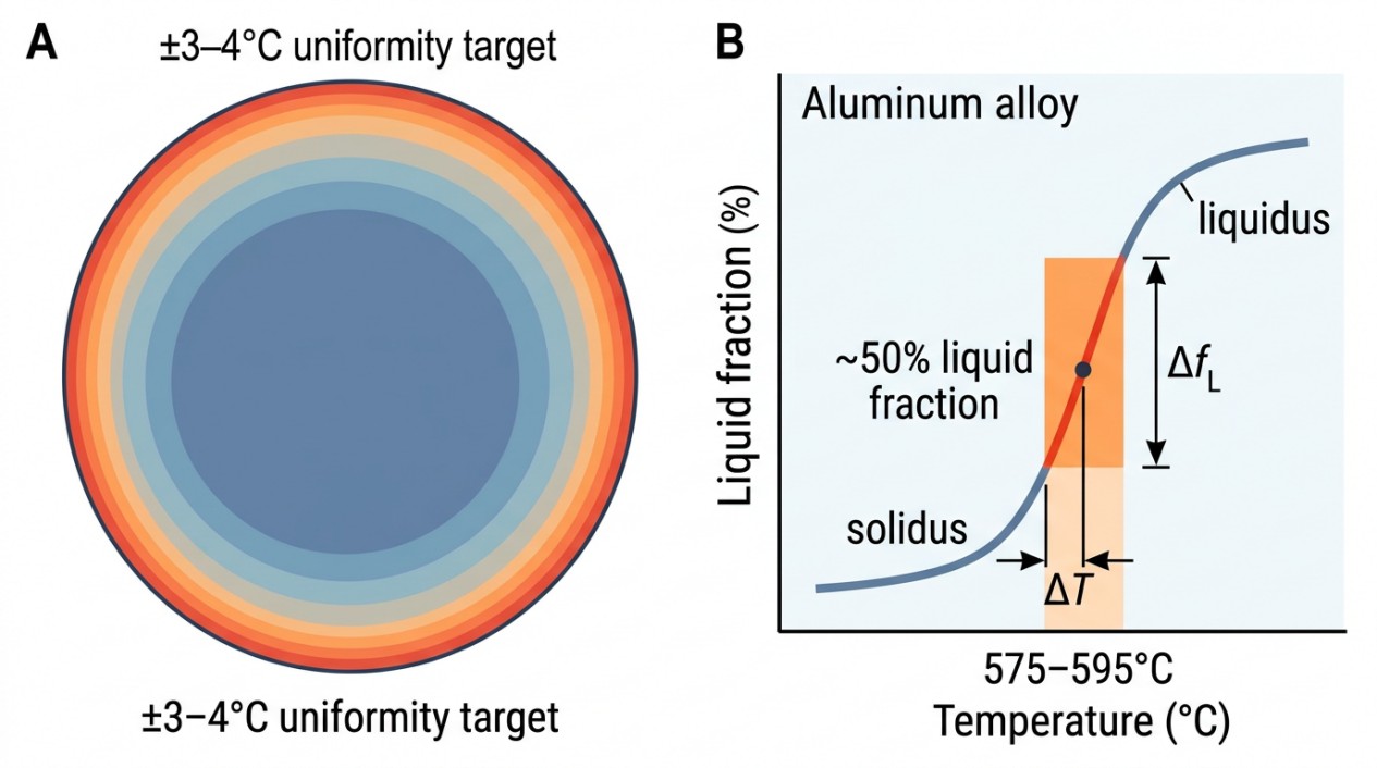
Semisolid metal processing involves heating metal billets or slugs to a temperature range where the alloy exists partially as solid and partially as liquid, typically around 50% liquid fraction for aluminum alloys such as 356 and 357. This state imparts unique rheological properties, including increased viscosity and predominantly laminar flow during casting, which enhances product integrity by reducing porosity and defects.
The critical challenge in SSM processing is achieving a uniform temperature distribution throughout the billet or slug to maintain a consistent liquid fraction. Even minor temperature gradients can cause significant variations in liquid fraction, adversely affecting flow behavior and casting quality. For aluminum alloys, the target temperature range is generally between 575°C and 595°C, with temperature uniformity maintained within ±3°C to ±4°C.
The geometry of the billet or slug also influences semisolid processing success. Optimal length-to-diameter ratios range from 1:2 to 1:3. Ratios exceeding this, such as 1:6, can lead to segregation issues and uneven heating.
Induction heating is uniquely suited for this application due to its rapid, controllable, and localized heating capabilities. The electromagnetic field induces eddy currents within the billet, generating heat volumetrically and allowing precise control over temperature profiles.
Coil Arrangements and Their Impact on Heating Uniformity
Two primary coil configurations are employed for induction heating of semisolid billets and slugs: vertical and horizontal arrangements.
Vertical Coil Arrangement
In the vertical configuration, billets are positioned upright on ceramic pedestals within the coil. This setup is compact and cost-effective, making it suitable for high-throughput operations. The coils are lowered around the billets, and power is applied to heat the slugs to the semisolid temperature. Once heated, the billets are transferred to casting machines for immediate forming.
This arrangement benefits from a smaller footprint and simpler mechanical design but requires careful management of electromagnetic forces and temperature uniformity to prevent shape distortion.
Horizontal Coil Arrangement
The horizontal coil setup resembles conventional billet heaters, where slugs are placed horizontally within the coil bore. To facilitate handling, specially designed carriers or "boats" transport the slugs through the coil. This arrangement allows for easier integration with horizontal casting machines and can accommodate larger billets.
While offering flexibility, horizontal coils may require more complex mechanical systems and careful design to minimize electromagnetic end effects and maintain uniform heating.
Electromagnetic Phenomena Affecting Semisolid Induction Heating
Induction heating of semisolid billets involves complex electromagnetic interactions that influence heating uniformity and billet integrity. Key phenomena include:
Electromagnetic End Effects
At the coil ends, the electromagnetic field distribution changes, leading to non-uniform heating known as end effects. These effects can cause localized overheating, resulting in excessive liquid fraction and potential dripping of molten metal. Proper coil design and power distribution are essential to mitigate these effects.
Lorentz Forces and Slug Distortion
The interaction of induced currents and magnetic fields generates Lorentz forces within the billet. These forces have radial and axial components and can cause billet deformation such as tilting or the "elephant foot" effect, where the billet base expands outward. Excessive forces can lead to shape distortion, surface erosion, and uneven heating.
Surface Erosion and Shape Changes
During heating, surface erosion may occur, particularly at the billet top, altering the geometry and electromagnetic coupling. These changes affect the eddy current paths and local heating rates, complicating temperature control.
Challenges in Mathematical Modeling of Induction Heating for Semisolid Processing
Accurate simulation of induction heating in semisolid billets is critical for system design and process optimization but presents significant challenges:
Complex Coupling of Physical Phenomena
Modeling must integrate electromagnetic fields, heat transfer, phase transformations, and fluid flow within the billet. The dynamic shape changes during heating, such as tilting and surface erosion, alter electromagnetic coupling and heat distribution, requiring advanced multiphysics simulations.
Variable Material Properties
Electrical resistivity, thermal conductivity, and specific heat capacity vary with temperature and phase fraction. Reliable data for semisolid alloys, especially during spheroidization stages, are scarce and often uncertain, limiting model accuracy.
Geometry Variations During Heating
The "elephant foot" effect and billet tilting change the coil-to-billet air gap non-uniformly along the billet length, affecting electromagnetic coupling. Simplified assumptions of cylindrical geometry lead to inaccuracies in predicted power density and temperature profiles.
Limitations of Commercial Software
Most available electromagnetic-thermal simulation tools do not fully account for the coupled phenomena or dynamic geometry changes inherent in semisolid induction heating. Consequently, simulation results should be treated as approximate guides rather than precise predictions.
Design and Operation of Commercial Induction Heating Systems for Semisolid Slugs
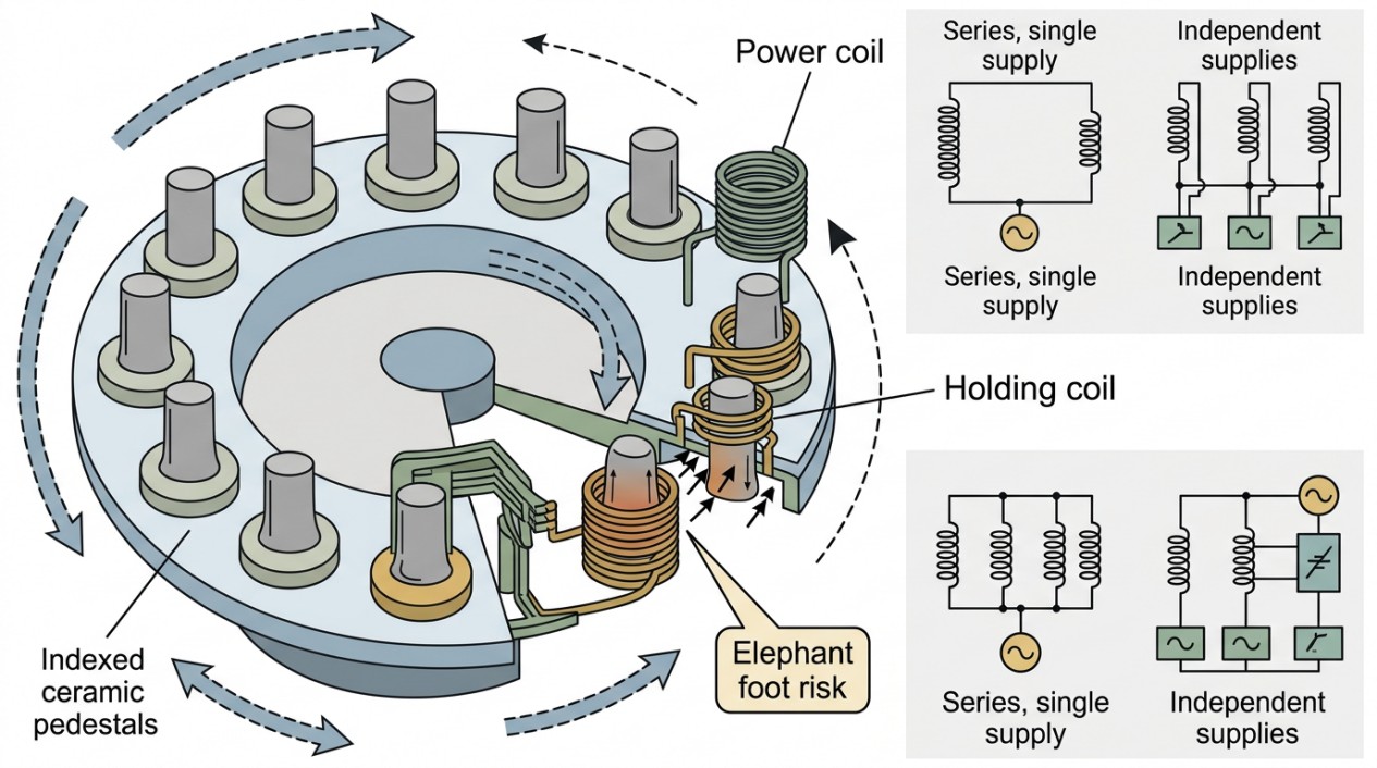
Industrial induction heating systems for semisolid processing are designed to meet stringent requirements for temperature uniformity, throughput, and process control.
Carousel-Style Vertical Induction Heaters
A common design features a carousel with multiple ceramic pedestals and induction coils arranged vertically. Slugs are loaded cold onto pedestals and indexed through a series of coils. Coils are lowered around the slugs, powered for a preset duration, then raised as the carousel indexes to the next position. This staged heating approach allows rapid heating followed by soaking to homogenize temperature and microstructure.
Typical systems use power supplies in the range of 350 kW at approximately 1 kHz frequency, suitable for slugs up to 5 kg. Heating times vary by slug diameter, with recommended durations around 9 minutes for 76 mm (3 in.) slugs, 12 minutes for 90 mm (3.5 in.), and 16 minutes for 100 mm (4 in.) slugs.
Coil Design and Power Supply Configurations
Two main approaches exist for powering multiple coils:
-
Design
All coils are connected in series and powered by one source. Different coil designs (power coils with more turns for rapid heating and holding coils with fewer turns for soaking) optimize the heating cycle.
-
Advantage
Reduces capital cost and simplifies control.
-
Limitation
Offers less flexibility in tailoring individual coil power profiles.
-
Design
Each coil is powered independently, allowing tailored power profiles and extended holding times if casting equipment experiences downtime.
-
Advantage
Enhances process control and flexibility.
-
Limitation
Increases capital investment and may complicate electromagnetic end effect management.
Automation and Maintenance Features
Automated pedestal cleaning systems remove residual debris such as drips or fragments knocked off during heating or handling. Maintaining clean pedestals ensures proper billet positioning and consistent heating cycles, critical for fully automated casting cells.
Frequency Selection and Process Control Considerations
Selecting the appropriate induction frequency is vital for controlling heating depth, temperature uniformity, and electromagnetic forces.
Frequency Impact on Heating Profile
Higher frequencies concentrate heating near the billet surface, while lower frequencies allow deeper penetration. Semisolid processing requires balancing these effects to achieve uniform temperature and liquid fraction distribution.
Minimizing Lorentz Forces
Excessive electromagnetic forces can distort billets and cause metal loss. Frequency and coil design must minimize axial forces that push molten metal out of the slug.
Process Monitoring
Real-time temperature measurement and feedback control are essential to maintain target semisolid conditions and compensate for variations in billet size, composition, or coil wear.
Practical Recipes for Induction Heating of Semisolid Slugs
Effective induction heating recipes for semisolid processing combine coil design, power input, heating time, and billet geometry to achieve consistent results.
| Parameter | Recommendation |
|---|---|
| Slug Geometry | Length-to-diameter ratios between 1:2 and 1:3 to minimize segregation and ensure uniform heating |
| Heating Sequence | Multistage cycle with initial rapid heating to solidus temperature followed by soaking to homogenize temperature and microstructure |
| Power Distribution | Coils with varying turns and power levels to manage electromagnetic end effects and maintain temperature uniformity along the slug length |
| Frequency Selection | Low kHz range (around 1 kHz) to balance penetration depth and minimize Lorentz forces |
| Heating Duration | 9 to 16 minutes for 3 to 4-inch diameters, adjusted based on slug diameter |
| Handling and Transfer | Ceramic pedestals or boats to support slugs during heating and transfer, minimizing mechanical deformation and contamination |
Summary Checklist: Induction Heating for Semisolid Processing
- Maintain billet/slug length-to-diameter ratios between 1:2 and 1:3 to prevent segregation and ensure uniform heating.
- Target semisolid temperature range of 575°C to 595°C with ±3°C to ±4°C uniformity for aluminum alloys.
- Employ vertical or horizontal coil arrangements based on plant layout, throughput, and integration requirements.
- Design coils and power supplies to manage electromagnetic end effects and minimize Lorentz forces causing billet distortion.
- Use multistage heating cycles with power coils for rapid heating and holding coils for soaking and homogenization.
- Select induction frequencies around 1 kHz to optimize heating depth and reduce electromagnetic forces.
- Incorporate automated pedestal cleaning to maintain consistent billet positioning and prevent debris accumulation.
- Recognize limitations of current mathematical models; use simulations as approximate guides and validate with experimental data.
- Implement real-time temperature monitoring and feedback control for precise process regulation.
- Consider capital cost versus process flexibility when choosing between single power supply and multiple independent power supplies for coil arrays.
Conclusion: Induction Heating for Semisolid Metal Processing
Induction heating for semisolid metal processing is a sophisticated interplay of electromagnetic, thermal, and metallurgical phenomena. Mastery of coil design, power management, and process control enables the production of high-quality semisolid billets and slugs, unlocking the benefits of semisolid casting in industrial applications.
FAQ about Induction Heating for Semisolid Metal Processing
Q: What temperature range is needed for semisolid processing of aluminum alloys, and why is uniformity so critical?
Aluminum alloys like 356 and 357 require heating to 575°C–595°C to achieve approximately 50% liquid fraction. Temperature uniformity within ±3°C to ±4°C is essential because even minor temperature gradients cause significant variations in liquid fraction, which directly affects flow behavior and can compromise casting quality by introducing porosity and defects.
Q: What causes the "elephant foot" effect during induction heating of billets?
The "elephant foot" effect—where the billet base expands outward—results from Lorentz forces generated by the interaction between induced eddy currents and magnetic fields within the billet. These electromagnetic forces have radial and axial components that can deform the billet shape, particularly at the base. Proper frequency selection (around 1 kHz) and coil design help minimize these forces.
Q: What is the recommended length-to-diameter ratio for semisolid slugs, and what happens if this ratio is exceeded?
The optimal length-to-diameter ratio is between 1:2 and 1:3. Ratios exceeding this range (such as 1:6) lead to segregation issues and uneven heating throughout the slug, compromising the uniformity of the semisolid state and negatively affecting the final casting quality.
Keep Learning
Induction Billet Heating: How to Achieve Uniform Heating
Induction billet heating prepares metal for forging, extrusion, or rolling by generating heat inside the workpiece. For steel billets, reaching the required exit temperature is only part of the task: the temperature distribution from surface to core and along the billet must also suit the forming process. Uniformity depends on how frequency, coil geometry, heat transfer, power distribution, and billet movement work together. This guide focuses on through-heating steel billets, particularly in progress......
How to Upgrade a 3D Printer Heated Bed with a Silicone Heater
If your 3D printer heated bed takes too long to reach temperature, develops uneven heating, or struggles to maintain a stable surface temperature, a silicone heater can be a practical upgrade. Faster warm-up and more uniform heat can improve first-layer consistency and reduce temperature-related printing issues. This guide explains how to identify when a heated-bed upgrade is needed, choose a suitable silicone heater, install it safely, and verify the results. Quick Answer A silicone heater can be a s......
How Graphene and MXene Flake Sensors Detect Force
Key Takeaways Flake networks sense force through microstructural change: Graphene and MXene coatings distribute conduction across overlapping platelets whose contacts shift under stretch or pressure, producing measurable resistance changes. Three mechanisms compete: Crack propagation, flake slippage, and quantum tunnelling each dominate at different deformation levels, giving many sensors multiple sensitivity regions rather than one uniform response. The substrate is an active partner: Elastomers, tex......
Conductive 2D Coatings Are a Matching Problem, Not a Miracle Ink
Key Takeaways Ink is a system, not a material: Conductivity depends on the combined effect of flake chemistry, solvent, additives, substrate, coating method, and post-processing—not on the 2D filler alone. Three carbon routes carry different trade-offs: GNPs demand dispersion engineering, GO shifts effort to a reduction step, and MXenes move the bottleneck to synthesis, storage, and oxidation control. Substrate geometry drives method selection: Spray and blade coating suit flat sheets; dip coating nat......
Graphene Heat Spreader Design: Layers and Interfaces
Key Takeaways Conductivity alone is not enough: A record thermal-conductivity value does not guarantee a cooler chip. Effective thickness, interface resistance, hot-spot geometry, and heat-sink connections all belong to the same thermal path. Few-layer graphene can outperform a single layer in practice: A few-layer sheet provides a larger heat-flow cross section and better tolerates transfer, embedding, and defects, even though its intrinsic conductivity is lower. Interface resistance is the bottlenec......
How Graphene Heat Spreaders Cool SOI Chip Hot Spots
Key Takeaways Buried oxide is a thermal bottleneck: SOI's insulating layer improves electrical isolation but traps heat near transistor channels, creating dangerous hot spots that package-level cooling alone cannot fix. Graphene enables lateral heat routing: Placing graphene or few-layer graphene beneath the buried oxide adds a high-conductivity sideways path, redistributing hot-spot energy toward dedicated sinks without removing any heat itself. Multi-source chips benefit most: Finite-element modelin......