
Load Matching in Induction Heating: Designing for Stability, Efficiency, and Real-World Variation
11 min
- Why the "Load" Is a Moving Target
- What Matching Networks Actually Do
- The Quiet Dominator: Q and Circulating Power
- Series vs. Parallel Resonant Behavior
- A Short Diagnostic Table: Symptom to Likely Matching Issue
- Commissioning Data: What to Log So You Can Fix Problems Fast
- Matching Range Strategy: Why Discrete Ranges Often Beat One Broad Range
- Layout as a Component: The Physical Resonant Loop
- High-Q Loads: Making Them Predictable
- A Commissioning Routine That Saves Weeks
- Capacitor Banks: RMS Current and Thermal Management
- Grounding and Bonding: Matching's Quiet Partner
- How to Document a "Known Good" Matching State
- What to Do When You Are Forced to Operate Near the Edge
- Worked Example: Why kW Alone Hides the Real Stress
- Changeover Discipline: Making Multi-Coil Production Predictable
- Why Inductance and Reactance Make Matching Nonlinear in Practice
- Typical Frequency Range and Current Capability
- Practical Tip: Match the Monitoring Bandwidth to the Waveform
- FAQ about Load Matching in Induction Heating
Key Takeaways
Dynamic Load: Induction heating loads are not fixed—coupling, material properties, and temperature all shift impedance during operation, making matching a continuous design challenge.
Q Factor Matters: High-Q loads can produce large circulating currents and capacitor stress even at modest delivered kW; design for the worst-case kVA, not just power.
Discrete Ranges Win: Transformer taps and capacitor steps that cover discrete matching ranges outperform a single broad-range configuration for multi-coil production.
Layout Is Circuit: Physical placement of capacitors, bus bars, and coil leads directly affects stray inductance, voltage stress, and system behavior—treat layout as a matching decision.
Log Everything: Commissioning with kW, kVA, current, voltage, frequency, and phase-angle data transforms troubleshooting from folklore into engineering.
Why the "Load" Is a Moving Target
An induction tank is typically the coil plus the workpiece, with capacitors supplying reactive power circulation. During a cycle, the effective impedance changes because resistivity rises, permeability can change dramatically (especially in ferromagnetic materials), and mechanical variation changes coupling. That is why two coils that look "identical" can require different matching steps, and why a process can drift after coil replacement.
What Matching Networks Actually Do
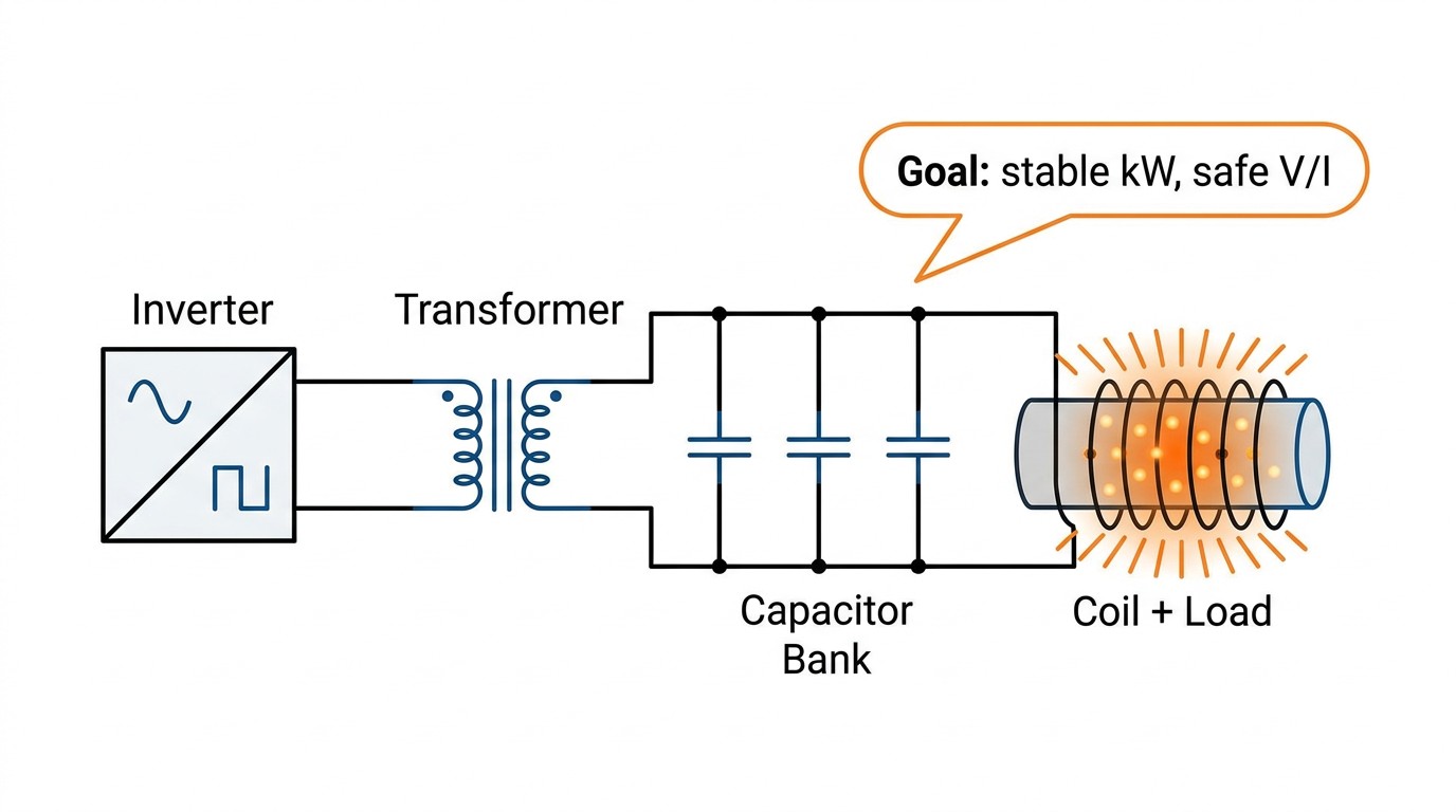
A good matching network performs two jobs at once:
First, it transforms impedance so the inverter sees a manageable load. Second, it ensures reactive power circulates locally in the tank rather than forcing the inverter to carry unnecessary kVA.
In industrial systems, matching is usually implemented with a combination of transformers (ratio or taps), capacitor banks (steps or modules), and sometimes switching to select discrete operating ranges.
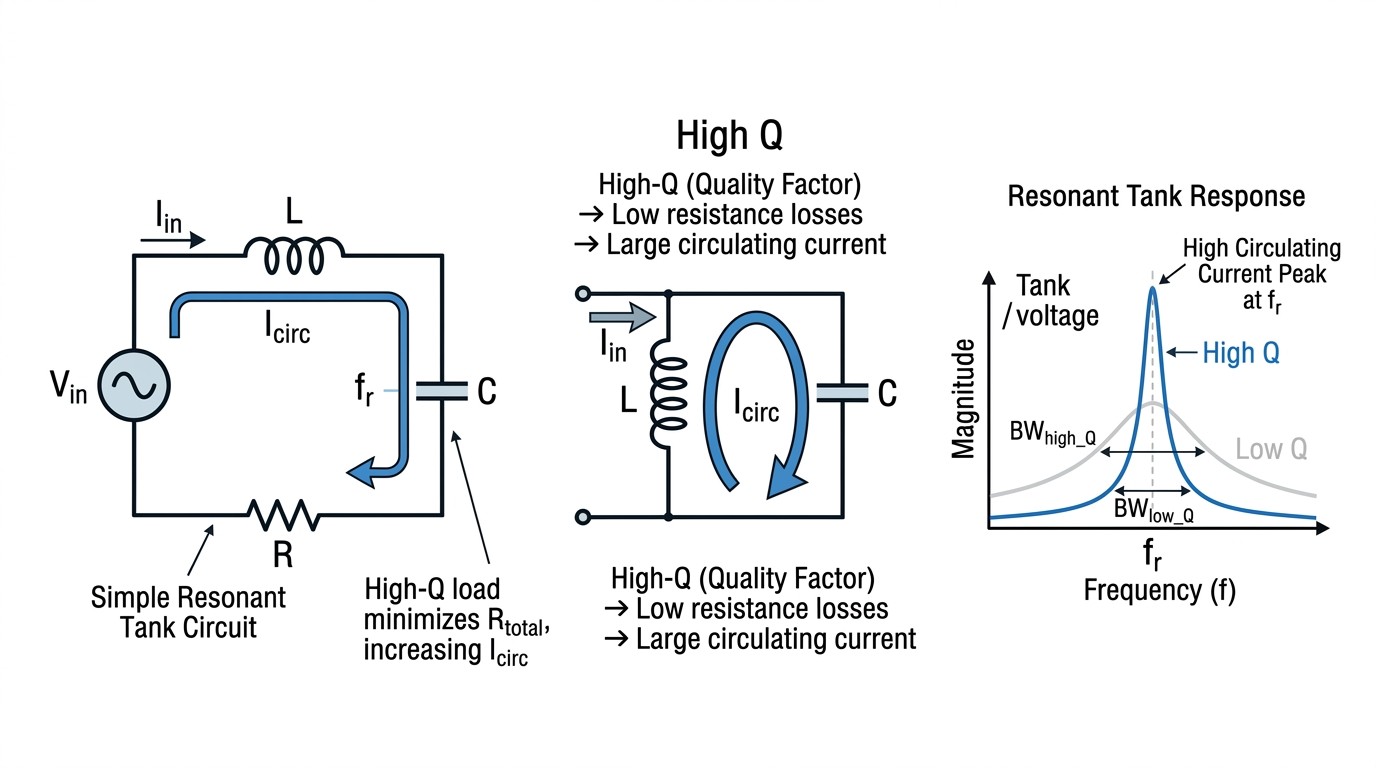
The Quiet Dominator: Q and Circulating Power
High Q loads are common in joining and in cases of loose coupling or nonmagnetic materials. High Q can be efficient, but it is unforgiving: small detuning shifts circulating current and tank voltage quickly. That's why "it only needs 20 kW" can still produce serious capacitor heating if the kVA circulation is large.
Instead of treating Q as a warning label, treat it as a design input. The matching network, sensors, and protection thresholds must be engineered to survive high circulating current conditions without nuisance trips.
Series vs. Parallel Resonant Behavior
Both series and parallel resonant arrangements exist in industrial induction equipment. Rather than focusing on textbook diagrams, focus on the observable consequences:
A series-resonant arrangement often feels "current-driven" near resonance; a parallel-resonant arrangement often feels "voltage-driven." In either case, detuning shifts where stress shows up. The right choice depends on inverter type, power range, and protection philosophy.
A Short Diagnostic Table: Symptom to Likely Matching Issue
| Symptom in Commissioning | Often Indicates | |
|---|---|---|
| 1 | Overvoltage trips at light load | High Q + detuning, insufficient matching range |
| 2 | Can't reach kW before current limit | Impedance too low, wrong ratio/taps, coil issue |
| 3 | Capacitors run hot | High circulating current, detuning, inadequate cooling |
| 4 | kW stable but part temperature wrong | Coupling issue, wrong frequency band, excessive losses |
Commissioning Data: What to Log So You Can Fix Problems Fast
The best way to avoid "mystery tuning" is to log enough signals to isolate causes. At minimum, capture kW, kVA, output current, output voltage, frequency, and a resonance/match indicator (often phase angle). Pair that with cooling flow/temperature and any motion/position signals that affect coupling.
This dataset turns troubleshooting into engineering rather than folklore.
Matching Range Strategy: Why Discrete Ranges Often Beat One Broad Range
Many plants run multiple part families, multiple coils, or multiple stations. A common mistake is to demand that one matching configuration cover everything. The result is usually a system that is never truly optimized: it operates near limits for some coils and wastes efficiency for others.
In practice, discrete matching ranges—transformer taps, capacitor steps, or configured banks—often produce a better result. Each range keeps the inverter and tank within a friendly region. Changeover becomes a controlled operation rather than an improvised tuning session.
Layout as a Component: The Physical Resonant Loop
At induction frequencies, the resonant loop is literally a piece of hardware: capacitor bank, bus bars, coil leads, and coil. Its geometry determines stray inductance, stray capacitance, and loss. That is why two systems with identical schematics can behave differently in the field.
Engineers should treat layout decisions as matching decisions. Placing capacitors physically close to where reactive current circulates reduces loop inductance and reduces voltage stress. Keeping bus runs short reduces parasitic resonance risk. These are not aesthetic rules; they are electrical requirements.
High-Q Loads: Making Them Predictable
High-Q conditions are common in joining and in loose-coupled setups. Predictable operation requires (1) matching hardware rated for high circulating current, (2) reliable sensing that does not saturate or alias at frequency, and (3) protection thresholds that distinguish normal high-Q operation from true faults.
A practical commissioning step is to test the system at the high-Q edge of the expected operating envelope. If the machine only behaves well at "nominal" coupling, it is not production ready.
A Commissioning Routine That Saves Weeks
Before full power trials, establish a baseline signature at reduced power. Record kW, kVA, current, voltage, frequency, and detuning indicators. Then deliberately vary coupling (within safe limits) to see how the system responds. This quickly reveals whether you have margin or whether you are operating on a cliff.
When this routine is documented, operators can reproduce it after maintenance events, reducing the risk of gradual drift.
Capacitor Banks: RMS Current and Thermal Management
Capacitor selection is often underestimated. In high-Q or detuned conditions, capacitor RMS current can increase dramatically even if delivered kW is unchanged. Because capacitor heating is driven by RMS current and internal resistance, an apparently small change in operating point can shorten capacitor life if thermal management is marginal.
Treat capacitor banks as consumable risk items unless you engineer them with margin: proper water cooling, low-inductance buswork, and monitoring of temperature rise. In high-duty applications, trending capacitor temperature can be as useful as trending inverter temperature.
Grounding and Bonding: Matching's Quiet Partner
Matching and layout decisions also affect noise and measurement stability. Poor bonding can create ground loops that corrupt current or voltage sensing, leading to false detuning alarms or unstable control. A robust system treats grounding as part of the circuit: short, intentional return paths and a clear single-point bonding strategy.
How to Document a "Known Good" Matching State
A surprisingly effective practice is to document the matching state in production terms: which tap, which capacitor step, what typical phase indicator value looks like, and what current/voltage ranges are normal for a standard test piece. This documentation prevents the line from slowly drifting into an unrecognized operating point after maintenance.
What to Do When You Are Forced to Operate Near the Edge
Sometimes constraints force you into a narrow operating window: limited space, fixed coil geometry, or a legacy power supply. When that happens, focus on increasing predictability. Tighten mechanical tolerances, shorten the resonant loop where possible, and log a reference signature for every coil. If the system must run near limits, disciplined monitoring and controlled changeover become the difference between production and chronic trips.
Worked Example: Why kW Alone Hides the Real Stress
Consider a 30 kW joining application with loose coupling to a nonmagnetic assembly. The delivered real power is modest, but the reactive circulation can be large because the tank is high-Q. In this scenario, the capacitor bank may carry high RMS current and the tank voltage may rise sharply near resonance. If you only watch kW, you may believe the system is lightly loaded, while components are operating near thermal limits.
Now compare that to a 30 kW surface heat-treat cycle with stronger coupling and lower Q. The same kW can produce lower circulating current and lower tank voltage, resulting in very different component heating and margin. This is why matching networks are specified by current and voltage capability, not just by delivered power.
The engineering takeaway is to evaluate the operating point with kW, kVA (or an equivalent indicator), and a resonance/detuning metric. A matching design that is robust in one application family can be fragile in another even at identical kW.
Changeover Discipline: Making Multi-Coil Production Predictable
If your plant changes coils frequently, treat matching changeover like a controlled procedure. Define a coil ID, define the matching range (tap and capacitor step), and define an acceptance signature that must be observed after changeover. This prevents a common failure mode: a coil is replaced, operators adjust frequency or time "until it works," and the station slowly migrates away from the validated process window.
A well-designed system makes this easier by providing built-in matching ranges, clear indicators, and recipes tied to coil IDs. Even without advanced automation, a disciplined checklist reduces scrap and stabilizes uptime.
Why Inductance and Reactance Make Matching Nonlinear in Practice
Even the basic terms in the circuit are nonlinear functions of operating conditions. Inductive reactance depends on frequency ($X_L = 2\pi fL$), but $L$ itself can change with coupling and workpiece state. Resistance also changes with temperature, and the effective impedance seen by the inverter is therefore not fixed. This is why matching that looks perfect at one part temperature can drift during long runs.
A practical implication is that "matching range" is not a static envelope; it is a dynamic envelope over the process cycle. If you validate matching only at the beginning of the cycle, you may miss where stress peaks later. Logging phase indicators and kVA proxies across the full cycle is often the fastest way to find where the system is losing margin.
Typical Frequency Range and Current Capability
Conventional heat treatment can span roughly 200 Hz to 600 kHz. That enormous range exists because processes vary from deep heating to very surface-focused heating. Across that range, current capability becomes a limiting factor: substantial current is typically required to heat metal effectively. If the supply cannot provide the required current, engineers compensate by changing coil geometry or by moving to a different frequency band, both of which have knock-on effects.
This is one reason many heat treat departments standardize on a small set of supply types and then design coils and fixtures around what is available. In those environments, matching discipline and coil documentation are what keep the process consistent across different stations.
Practical Tip: Match the Monitoring Bandwidth to the Waveform
Design Tip
If your inverter output is not a pure sine wave, the measurement chain matters. True RMS capability is necessary but not sufficient; bandwidth and filtering determine whether you are measuring the waveform you think you are measuring. When measurement bandwidth is too low, phase indicators can lag and detuning detection can become noisy, which in turn makes control feel unstable. During commissioning, validate that your sensors and meters behave correctly at the actual operating frequency and at the actual voltage levels present in the tank.
FAQ about Load Matching in Induction Heating
Q: Why do "replacement coils" often require rematching?
Small geometric differences change inductance, stray coupling, and effective impedance. At induction frequencies, millimeter-scale differences can shift resonance and circulating current.
Q: Is frequency the easiest knob for fixing mismatch?
Frequency changes can help, but they also change penetration behavior. Discrete matching changes (taps, capacitor steps) usually move the operating point more predictably without changing the physics of where heat is generated.
Q: What's the best single signal to detect detuning?
A resonance indicator based on voltage–current phase relationship is often more informative than kW alone, because it shows how close the tank is to the region where voltage/current stress rises sharply.
Conclusion: Load Matching in Induction Heating
When matching is engineered as a system, the inverter operates in a friendly region, recipes become portable, and the process tolerates normal variation. When matching is treated as an afterthought, teams compensate with frequency tweaks and longer heat times—often sacrificing quality and efficiency. Treat matching as the bridge between power electronics and process control, and the rest of commissioning gets dramatically easier.
Keep Learning
Simultaneous Dual-Frequency Induction Heating: When One Frequency Forces the Wrong Compromise
Key Takeaways One frequency, one compromise: When geometry demands both deep bulk heating and controlled surface gradients simultaneously, a single frequency forces an unacceptable trade-off—dual-frequency widens the process window. Give each channel a role: Assign the lower frequency to bulk penetration and the higher frequency to surface shaping. Structured recipe development follows naturally from this separation. Validate with metrics, not opinions: Dual-frequency is justified only when controlled......
Power Supplies by Application Family: Joining, Mass Heating, and Strip Processing
Key Takeaways Joining operations (brazing, soldering, bonding) demand higher frequencies and matching flexibility to handle variable coil coupling and precision surface heating. Mass heating lines (billets, bars, slabs) prioritize continuous duty, efficiency, and ruggedness at high power levels with multi-coil zone control. Strip processing requires architectures that separate control electronics from high-frequency inverter modules to cope with harsh installation environments. Specifying only kW and ......
Simultaneous Dual-Frequency Induction Power: When One Frequency Forces the Wrong Compromise
Key Takeaways Dual-frequency is justified by robustness, not complexity: It should only be adopted when a single frequency forces an unacceptable compromise between surface and bulk heating requirements. Give each frequency a defined role: Assign the lower frequency to bulk heating/penetration and the higher frequency to surface shaping—then develop recipes one variable at a time. The combining network is the engineering center of gravity: Frequency-selective coupling paths, thermal rating for worst-c......
Applying Induction Power Supplies in the Real World: Constraints That Decide Uptime and Quality
Key Takeaways Application constraints dominate real-world performance: Two induction systems with identical kW ratings can behave very differently depending on cable length, cooling water temperature, dust levels, and fixture repeatability. Design for drift, not for perfect day one: Coils deform, filters clog, sensors drift, and connectors loosen under thermal cycling. Baseline monitoring during commissioning is essential. Mechanical repeatability often beats control complexity: Improving fixturing an......
Medium- and High-Frequency Transformers in Induction Systems: Design Drivers Engineers Should Actually Care About
Key Takeaways Not Passive: Transformers set the electrical operating point for the entire induction station—coil voltage, current, capacitor stress, and inverter margin all depend on transformer choice. Frequency Effects: At higher frequencies, winding losses and stray capacitance dominate; a transformer that looks fine on turns ratio can fail a duty-cycle test if loss distribution is wrong. Placement Matters: Moving the transformer and capacitor bank closer to the coil reduces high-frequency loop len......
Load Matching in Induction Heating: Designing for Stability, Efficiency, and Real-World Variation
Key Takeaways Dynamic Load: Induction heating loads are not fixed—coupling, material properties, and temperature all shift impedance during operation, making matching a continuous design challenge. Q Factor Matters: High-Q loads can produce large circulating currents and capacitor stress even at modest delivered kW; design for the worst-case kVA, not just power. Discrete Ranges Win: Transformer taps and capacitor steps that cover discrete matching ranges outperform a single broad-range configuration f......