
Power vs. Frequency in Induction Heating: How to Choose a Starting Point Without Guesswork
10 min
- The Power–Frequency Map: What It Really Represents
- Why Frequency Is a Process Variable (Not Just an Electrical Setting)
- A Practical Starting Workflow (Before Detailed Modeling)
- Common Engineering Pitfalls
- Quick Comparison Table: How Frequency Choice Shifts the Design
- How to Translate a Thermal Requirement into an Electrical Starting Point
- Why Application Clusters Exist: The Engineering Constraints Behind Them
- A Practical Checklist for Early Frequency Selection Meetings
- Practical Note: Frequency, Penetration, and Temperature Are Coupled
- A More Concrete View of the Power–Frequency Trade Space
- FAQ about Induction Heating Frequency Selection
Key Takeaways
Point 1: Frequency primarily governs penetration behavior and current distribution in the workpiece, while power governs how quickly you can deliver the required energy.
Point 2: A disciplined first pass uses three layers: process physics, energy balance, and electrical feasibility.
Point 3: Frequency selection has second-order consequences like instrumentation, EMC, and maintenance that show up later if ignored.
In induction heating projects, the fastest way to burn schedule is to treat frequency selection as a late-stage tuning knob. In reality, frequency is one of the earliest decisions that constrains everything that follows: coil geometry, matching network stress, inverter device choice, cable losses, and ultimately whether you can hit the thermal specification with margin.
This engineering guide explains how to use the power–frequency landscape as a practical map. The goal is not to replace electromagnetic/thermal simulation, but to help you pick a sensible starting region (and avoid obviously bad combinations) before you invest in coil fabrication and power supply procurement.
The Power–Frequency Map: What It Really Represents
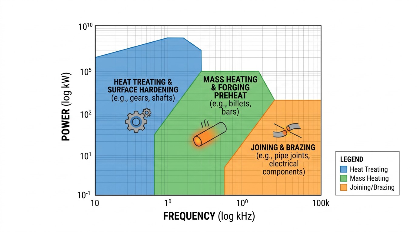
Induction heating loads do not “want” a particular frequency—your process does. Frequency primarily governs penetration behavior and current distribution in the workpiece, while power governs how quickly you can deliver the required energy. When you plot typical industrial applications on a power–frequency plane, you get clusters rather than a single line because different processes optimize for different constraints.
For example, surface-dominated processes can tolerate shallow penetration and often benefit from higher frequency. Through-heating processes for larger cross sections generally need lower frequency to drive current deeper and reduce extreme surface gradients. Joining operations (brazing/soldering/bonding) frequently sit in a high-frequency, lower-power region because the heated zone is intentionally small and controllability matters more than bulk throughput.
Why Frequency Is a Process Variable (Not Just an Electrical Setting)
Engineers sometimes treat frequency as “whatever the power supply offers.” That mindset fails when the thermal spec is tight. Frequency affects:
- Penetration behavior and therefore where heat is generated initially.
- Coil and bus losses because skin and proximity effects increase AC resistance.
- Component feasibility because semiconductors, magnetics, and capacitors have frequency-dependent limits.
A system that is electrically stable at a few kilohertz can become sensitive at tens or hundreds of kilohertz if layout parasitics dominate. Conversely, a system optimized for high frequency can be unnecessarily large and expensive if the process would have worked at lower frequency.
A Practical Starting Workflow (Before Detailed Modeling)
A disciplined first pass uses three layers: process physics, energy balance, and electrical feasibility.
-
Step 1: Clarify "Good Heating"
Is it surface temperature, austenitization depth, exit uniformity for forming, or a joint interface temperature for brazing? Without that, you can’t decide whether penetration depth is the primary constraint.
-
Step 2: Energy Estimate
Perform an energy estimate to determine the scale of required power. Even if you later refine with simulation, the estimate tells you whether you are in “tens of kW” territory or “multi-MW” territory.
-
Step 3: Electrical Feasibility
Sanity-check the electrical operating point. If the implied coil current is extreme, or the implied coil voltage is uncomfortably high, you may need a different frequency band, a different matching strategy, or a different coil topology.
Common Engineering Pitfalls
Mistakes to Avoid
- Using room-temperature assumptions for hot operation. Material resistivity rises with temperature; magnetic behavior can change sharply; the effective coupling and penetration shift during the cycle.
- Ignoring distribution, not just average temperature. Many processes fail not because average power is wrong, but because gradients are wrong.
- Underestimating conductor losses at higher frequency. Cable, bus, and coil losses can dominate if AC resistance is not managed.
When these pitfalls are addressed early, the first prototype typically lands closer to the production-capable design.
Quick Comparison Table: How Frequency Choice Shifts the Design
| Decision Driver | Lower Frequency Tends to Favor | Higher Frequency Tends to Favor |
|---|---|---|
| Heating objective | Through-heating, deeper penetration | Surface-focused heating, small features |
| Typical power scale | Higher (often mass heating) | Lower to moderate (often joining/heat treating) |
| Coil/cable behavior | Lower AC resistance sensitivity | Higher AC resistance sensitivity |
| Control sensitivity | Often more tolerant to parasitics | More sensitive to layout and matching |
| Equipment implications | Larger magnetics, high current | Faster switching, tighter layout discipline |
How to Translate a Thermal Requirement into an Electrical Starting Point
Most teams begin with a thermal statement: “heat this region to X °C in Y seconds” or “deliver billets at Z °C with a maximum gradient.” The induction system then has to translate that into coil current, coil voltage, and a frequency band that produces the right penetration behavior.
A practical workflow is to first estimate energy and average power, then ask what that implies for the electrical stress. Energy is roughly mass times heat capacity times temperature rise (plus phase-change or transformation terms if relevant). Average power is energy divided by heat time. From there, you apply an efficiency factor—not because you know it precisely on day one, but because you need to know whether you are in the 20 kW class or the 2 MW class.
Once you have an estimated power scale, you can sanity-check whether your frequency choice pushes the electrical design into an uncomfortable corner. At very high frequencies, conductor losses can become a large fraction of delivered power unless the coil leads, bus bars, and capacitor placement are engineered carefully. At lower frequencies and very high power, mechanical forces on the coil and buswork (from high currents) become a dominant design constraint, and transformer/matching choices often drive cabinet size.
Why Application Clusters Exist: The Engineering Constraints Behind Them
The reason the power–frequency plane produces clusters is that each application family has a different “dominant pain.” In surface heat treating, the pain is often heat pattern control and repeatability—small changes in coupling can change case depth. In mass heating, the pain is energy cost and uniformity—if gradients are wrong, the forming process fails even if average temperature is correct. In joining, the pain is selectivity—heat must go into the joint without ruining surrounding material.
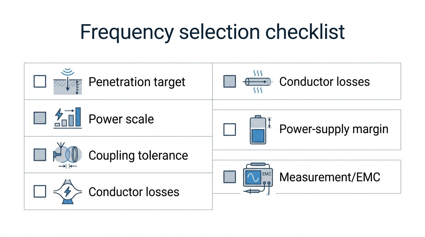
A Practical Checklist for Early Frequency Selection Meetings
Engineers can avoid many iterations by answering a small set of questions up front. The point is not to be perfect; the point is to prevent obviously wrong equipment selection.
- What is the maximum allowed surface-to-core temperature difference at the end of heating?
- Is penetration depth itself a critical-to-quality variable (e.g., case depth) or is bulk temperature the main target?
- Will the part pass through magnetic transitions (e.g., near Curie in steels) that change coupling during the cycle?
- How repeatable is part positioning, and what is the worst-case part-to-coil gap variation?
- What is the likely operating point most of the time: full power, partial power, or frequent ramps?
When these answers are clear, you can choose a frequency band that makes the process feasible and leaves room for control.
Design Consequences Engineers Often Underestimate
Frequency selection has second-order consequences that show up later if ignored. One is instrumentation: higher frequency systems require more careful measurement and filtering to provide reliable kW, kVA, and resonance indicators. Another is EMC: higher frequency switching and tank voltages can couple into nearby sensors if grounding and bonding are not designed as a system. A third is maintenance: compact high-frequency systems can be very reliable, but only if cooling, dust protection, and connector integrity are maintained.
Practical Note: Frequency, Penetration, and Temperature Are Coupled
One reason frequency selection is easy to get wrong is that penetration behavior is not constant throughout the cycle. As the workpiece heats, resistivity rises and (for magnetic alloys) permeability can change, which shifts effective penetration and coupling. That means the heating pattern you see at the beginning of the cycle may not be the pattern that dominates at the end. Engineers who account for this early typically choose frequency bands with more margin and design coils and matching networks that tolerate the shift.
A More Concrete View of the Power–Frequency Trade Space
A subtle but important detail in the source material is that the “power–frequency map” is not only about the workpiece physics. It is also about what the power supply hardware can do reliably at that operating point. At a given frequency, the switching devices, buswork, and capacitors must be rated with adequate margin, and that margin is harder to maintain as frequency rises and parasitic effects become more influential. In other words, a frequency band that looks attractive for penetration behavior may still be a poor choice if it forces the power electronics into a low-margin corner.
The map also reflects the fact that the coil and workpiece jointly define parameters the supply must tolerate: coil voltage, coil current, and the effective load power factor or Q. When engineers specify only kW and kHz, they under-specify the real electrical requirement. Two coils at the same frequency and kW can demand very different current and kVA circulation depending on coupling and Q, and that difference shows up as capacitor heating, bus heating, and nuisance overvoltage events.
A practical way to internalize this is to treat the early frequency decision as a three-way compromise: penetration behavior, conductor losses (skin/proximity), and power-supply margin. If you choose a band that is feasible in all three, most later design work becomes refinement rather than rescue.
Component Rating Margin: Why It Shows Up as “Reliability”
The source emphasizes that power components must be rated for operation at the selected frequency and that the circuit must operate them with adequate margin to yield high reliability. In commissioning terms, this is what separates a machine that runs “only when perfectly tuned” from a machine that tolerates everyday variation. Margin is not only a nameplate concept; it is the gap between your normal operating signature and your protection limits under worst-case coupling and temperature.
If you want one concrete action item: when you validate an induction station, do not validate only at nominal coupling. Validate at the worst-case part-to-coil gap, at the hottest expected inlet water, and at the highest expected ambient temperature. Those conditions reveal whether your frequency choice left enough electrical margin.
FAQ about Induction Heating Frequency Selection
Q: What's the fastest way to choose a frequency band before simulation?
Start from the heating objective (surface vs. through), estimate part size and required gradients, then use the power–frequency map to select the closest application cluster. Validate with a simple energy/power estimate and sanity-check coil voltage/current feasibility.
Q: Why do higher frequencies often make equipment smaller but more finicky?
Higher frequency can reduce required current for a given heating effect and allow smaller magnetic components, but it increases sensitivity to skin/proximity losses and layout parasitics, which can reduce stability margins.
Q: When should you treat frequency as a “locked” parameter?
When penetration behavior is a critical-to-quality variable (case depth, surface condition, thin strip heating efficiency). In those cases, changing frequency is a process change and should be controlled like any other recipe-critical parameter.
Conclusion: Use the Map to Reduce Iteration
A power–frequency map is not a replacement for simulation, but it is a strong filter against bad starting points. If you choose a frequency band consistent with your process objective and power scale, the rest of the system design becomes an optimization problem rather than a rescue mission.
Keep Learning
Simultaneous Dual-Frequency Induction Heating: When One Frequency Forces the Wrong Compromise
Key Takeaways One frequency, one compromise: When geometry demands both deep bulk heating and controlled surface gradients simultaneously, a single frequency forces an unacceptable trade-off—dual-frequency widens the process window. Give each channel a role: Assign the lower frequency to bulk penetration and the higher frequency to surface shaping. Structured recipe development follows naturally from this separation. Validate with metrics, not opinions: Dual-frequency is justified only when controlled......
Power Supplies by Application Family: Joining, Mass Heating, and Strip Processing
Key Takeaways Joining operations (brazing, soldering, bonding) demand higher frequencies and matching flexibility to handle variable coil coupling and precision surface heating. Mass heating lines (billets, bars, slabs) prioritize continuous duty, efficiency, and ruggedness at high power levels with multi-coil zone control. Strip processing requires architectures that separate control electronics from high-frequency inverter modules to cope with harsh installation environments. Specifying only kW and ......
Simultaneous Dual-Frequency Induction Power: When One Frequency Forces the Wrong Compromise
Key Takeaways Dual-frequency is justified by robustness, not complexity: It should only be adopted when a single frequency forces an unacceptable compromise between surface and bulk heating requirements. Give each frequency a defined role: Assign the lower frequency to bulk heating/penetration and the higher frequency to surface shaping—then develop recipes one variable at a time. The combining network is the engineering center of gravity: Frequency-selective coupling paths, thermal rating for worst-c......
Applying Induction Power Supplies in the Real World: Constraints That Decide Uptime and Quality
Key Takeaways Application constraints dominate real-world performance: Two induction systems with identical kW ratings can behave very differently depending on cable length, cooling water temperature, dust levels, and fixture repeatability. Design for drift, not for perfect day one: Coils deform, filters clog, sensors drift, and connectors loosen under thermal cycling. Baseline monitoring during commissioning is essential. Mechanical repeatability often beats control complexity: Improving fixturing an......
Medium- and High-Frequency Transformers in Induction Systems: Design Drivers Engineers Should Actually Care About
Key Takeaways Not Passive: Transformers set the electrical operating point for the entire induction station—coil voltage, current, capacitor stress, and inverter margin all depend on transformer choice. Frequency Effects: At higher frequencies, winding losses and stray capacitance dominate; a transformer that looks fine on turns ratio can fail a duty-cycle test if loss distribution is wrong. Placement Matters: Moving the transformer and capacitor bank closer to the coil reduces high-frequency loop len......
Load Matching in Induction Heating: Designing for Stability, Efficiency, and Real-World Variation
Key Takeaways Dynamic Load: Induction heating loads are not fixed—coupling, material properties, and temperature all shift impedance during operation, making matching a continuous design challenge. Q Factor Matters: High-Q loads can produce large circulating currents and capacitor stress even at modest delivered kW; design for the worst-case kVA, not just power. Discrete Ranges Win: Transformer taps and capacitor steps that cover discrete matching ranges outperform a single broad-range configuration f......