
Induction Heating’s Electromagnetic Building Blocks: Fields, Eddy Currents, and Why Current Doesn’t Spread Evenly
11 min
- The Physics of Non-Contact Heating
- Why Current Isn’t Uniform: The Five Core Effects
- Magnetic Permeability and Secondary Properties
- Electrical Resistivity: The Foundation of Resistance
- Process Debugging: What to Verify First
- Design Knobs for the Practicing Engineer
- FAQ
Induction heating (IH) is more than just a metal-heating process; it is a precise application of electromagnetic fields and material science. At its core, IH relies on the interaction between alternating coil voltage and the resulting magnetic field that penetrates a workpiece. This interaction is governed by distinct electromagnetic phenomena that dictate where heat is generated and how efficiently the system runs. For engineers designing or troubleshooting induction systems, mastering these building blocks—from Joule heating to distribution effects like skin and proximity—is essential for achieving predictable thermal results.
The Physics of Non-Contact Heating
The process begins when an alternating voltage is applied to an induction coil, producing an alternating current (AC). This current generates a time-variable magnetic field that oscillates at the same frequency. This field induces eddy currents in any nearby conductive workpiece. These induced currents flow in the opposite direction of the coil current while maintaining the same frequency, effectively transferring energy without physical contact.
The transformation of electrical energy into thermal energy occurs via the Joule effect (I²R). While the magnetic field provides the mechanism for energy transfer, the material's electrical resistivity (R) generates heat directly within the workpiece. This internal heat generation distinguishes induction from convection or radiation, as heat is created within the part rather than soaking from the surface inward. Consequently, any variation in the magnetic field—due to coil geometry or nearby conductors—directly impacts heat generation uniformity.
Why Current Isn’t Uniform: The Five Core Effects
In induction heating, assuming current spreads evenly through a conductor is fundamentally incorrect. Several electromagnetic phenomena force current to redistribute, creating heat source non-uniformity and temperature gradients. Engineers must account for these five primary effects to control hardness patterns and system efficiency.
1. Skin Effect: The Surface Layer Phenomenon
The skin effect is the most prevalent phenomenon in IH. When AC flows through a conductor, current density is highest at the surface and decreases exponentially toward the core. Approximately 86% of the power is concentrated in a surface layer known as the current penetration depth (δ). In practical engineering, this effect enables surface hardening by restricting heat to the outer layer of steel during high-frequency applications.
When through-heating large billets, the skin effect can be a challenge. If the frequency is too high, the surface may melt while the core remains cold, creating thermal gradients that lead to structural issues. The penetration depth is dynamic; as the material heats, its electrical resistivity increases, causing the skin depth to grow. For ferromagnetic materials like carbon steel, the skin depth expands drastically once the surface passes the Curie point and relative magnetic permeability drops to unity.
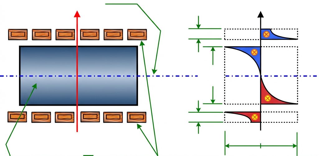
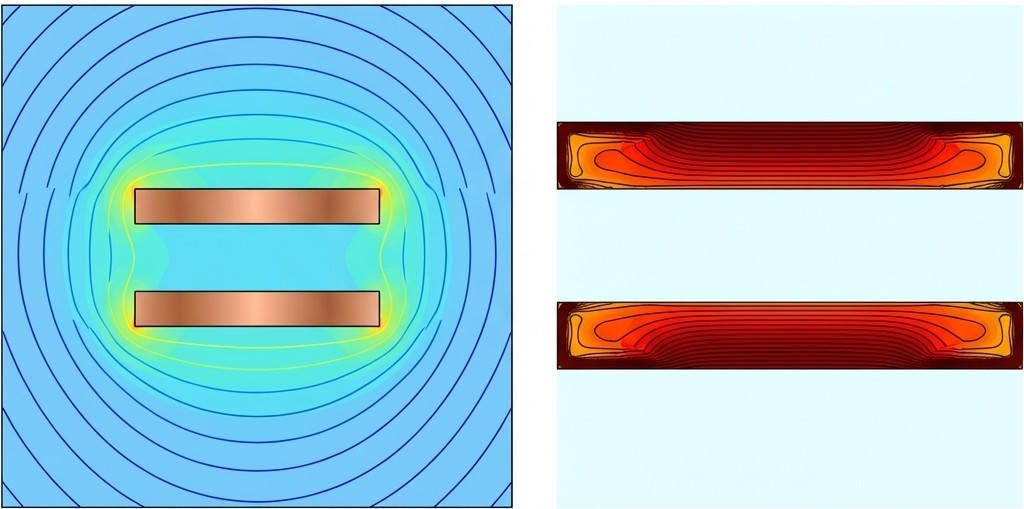
2. Proximity Effect: Interaction Between Conductors
The proximity effect occurs when two current-carrying conductors are near each other. Their magnetic fields interact, causing currents to redistribute. In induction heating, currents in the coil and workpiece flow in opposite directions, concentrating in the areas facing each other. This makes the coupling distance (the air gap) a critical design knob; a smaller gap leads to more intense, localized heating as the magnetic field is squeezed between the surfaces.
The proximity effect is often responsible for hot spots in non-symmetrical systems. If a workpiece is off-center, the side closer to the inductor will experience higher current density and faster heating. Unintended proximity effects can also occur in nearby fixtures or cabinets. If conductive components are placed too close to the induction coil without shielding, they will absorb energy, leading to equipment damage or energy waste.
3. Ring Effect: The Inside-Surface Concentration
When a conductor is bent into a ring or coil, the ring effect forces the current to flow primarily along the inside surface. This occurs because magnetic flux lines concentrate inside the ring, creating a lower impedance path along the inner circumference. While beneficial when the workpiece is inside the coil, this effect challenges internal diameter (I.D.) heating.
When an inductor is placed inside a hole, the ring effect pulls current toward the inside of the coil turns—away from the workpiece. This "de-coupling" reduces efficiency and increases copper losses. Engineers counteract this by using magnetic flux concentrators to force current back toward the "open surface" of the inductor, ensuring effective heat transfer to the workpiece I.D.
4. Slot Effect: Squeezing the Current
The slot effect is an engineered phenomenon where a magnetic flux concentrator (like C-shaped laminations) is used to "squeeze" inductor current to the open surface of a slot. By providing a low-reluctance path for the magnetic field, the concentrator forces current to flow exactly where it is needed for selective area heating. This improves inductor-to-workpiece coupling and is essential for precision tasks like localized hardening.
5. End and Edge Effects: Field Distortions
End and edge effects occur where the magnetic field is distorted at workpiece boundaries, causing non-uniform temperature profiles. For instance, in bar end heating, magnetic forces might eject a nonmagnetic bar or pull a ferromagnetic one toward the center. Edges of slabs often overheat because they receive heat from three sides (two surfaces and the edge), whereas the central part receives heat from only two.
Magnetic Permeability and Secondary Properties
While electrical resistivity is the foundation of resistance, magnetic permeability is the foundation of flux conduction. Relative magnetic permeability (μr) indicates the ability of a material to conduct magnetic flux better than air. For induction heating, materials are classified into three groups based on their magnetization ability:
- Nonmagnetic (Paramagnetic and Diamagnetic): Materials like aluminum, copper, and titanium have a μr very close to 1, meaning magnetic properties have little impact on skin depth.
- Ferromagnetic: Materials like iron and carbon steel exhibit high μr values, leading to shallow skin depths and high heating efficiency at room temperature.
The permeability of ferromagnetic materials is not constant; it is a complex function of magnetic field intensity (H), temperature, and microstructure. As field intensity (H) increases beyond a critical value, permeability decreases—a process known as magnetic saturation. In high-power applications, the field at the workpiece surface often drives the material toward saturation, lowering the effective μr.
Key Electromagnetic Properties at a Glance
- Saturation Flux Density: The maximum magnetic flux density a material can hold before increasing H yields diminishing returns in B.
- Coercive Force: The magnetic field intensity required to reduce a material's magnetization to zero after reaching saturation.
- Hysteresis Loss: Energy dissipated as heat during magnetization reversal, typically secondary to Joule heating from eddy currents.
- Relative Permittivity: A critical factor for dielectric heating that typically has no measurable impact on metallic induction heating.
- Magnetic Susceptibility (χ): The amount by which relative permeability differs from unity (μr = χ + 1).
The Curie temperature is the most critical milestone for ferromagnetic materials. At this point (approx. 732°C to 768°C for carbon steels), the material loses its ferromagnetic properties and μr drops to 1. This abrupt change alters the load seen by the power supply; penetration depth increases, the heating pattern spreads deeper, and coil impedance shifts, requiring system adjustments to maintain efficiency.
Electrical Resistivity: The Foundation of Resistance
Induction system performance depends heavily on electrical resistivity (ρ). Metals are excellent conductors but vary widely in resistive behavior, generally categorized into low-resistive metals like copper and high-resistive alloys like stainless steel. The table below illustrates common resistivity values at room temperature:
|
Material (at Room Temp) |
Resistivity (μΩ·m) |
|---|---|
|
Silver |
0.015 |
|
Copper |
0.017 |
|
Aluminum |
0.027 |
|
Tungsten |
0.054 |
|
Nickel |
0.068 |
|
Mild carbon steel |
0.16 |
|
Titanium |
0.42 |
|
Stainless steel |
0.7 |
|
Nichrome |
1 |
|
Graphite |
7–9 |
These values are not static. Resistivity varies with temperature, composition, and microstructure. Temperature dependence is the most critical variable; as temperature rises, atomic vibrations increase resistance to electron flow. This means the load's resistance is constantly evolving during the heating cycle.
Temperature Dependence and the Alpha Coefficient
For most pure metals, resistivity rises with temperature, often approximated as : , where α is the temperature coefficient. However, this linear approximation fails during phase transformations or lattice changes. In carbon steels or graphite, α is nonlinear. For certain graphite grades, α can even be negative, causing resistivity to decrease as temperature increases, which may lead to runaway heating if uncontrolled.
Engineering Warning: Avoid "Average" Resistivity
Assuming constant resistivity is a common design pitfall. Since resistivity can increase four to six times during heating, using an average value leads to misleading conclusions about heat depth and efficiency. A process designed on room-temperature resistivity will likely see heating rates slow dramatically as the part reaches target temperature.
Impact of Composition and Microstructure
Chemical composition significantly affects resistivity by distorting the metal lattice. Even trace impurities in iron can notably increase resistivity. In binary alloys like Cu–Ni, resistivity often follows a bell-shaped curve, peaking at 50% alloying content. For carbon steels, resistivity increases continuously with carbon content, meaning SAE 1060 steel heats differently than SAE 1008 under identical conditions.
Microstructure also influences resistive behavior. Finer grain sizes generally correspond to higher resistivity, while in powder metallurgy, resistivity decreases as density increases. Understanding how plastic deformation and heat treatment affect the lattice is vital for tuning induction systems to a material's actual behavior during processing.
Process Debugging: What to Verify First
When an induction process yields unexpected results like localized overheating or inconsistent hardness, engineers should verify these fundamental parameters first. This checklist addresses the core electromagnetic building blocks that dictate thermal delivery:
IH Troubleshooting Checklist
- Material Grade & Carbon Content: Verify the exact chemical composition as small shifts in carbon change both resistivity and the Curie point.
- Initial Temperature Range: Confirm whether you are starting with room-temperature or pre-heated parts, as resistivity is temperature-dependent.
- Coil-to-Workpiece Air Gap: Check for symmetry to ensure the proximity effect does not create hot spots on the side with a smaller gap.
- Nearby Conductive Fixtures: Identify metal fixtures within the magnetic field that might be absorbing power or creating safety hazards.
- Applied Frequency: Ensure the frequency is appropriate for the target penetration depth, recalling that δ is inversely proportional to frequency.
- Flux Concentrator Condition: Verify that concentrators are properly positioned and not saturated to maintain effective current steering via the slot effect.
Design Knobs for the Practicing Engineer
Translating these phenomena into practice involves adjusting specific "knobs" to control the heating pattern. Frequency is the primary tool for managing the skin effect, while coil geometry and flux concentrators leverage the ring and slot effects to steer current. Workpiece orientation also dictates whether a part acts as electromagnetically thick or thin based on how eddy currents loop.
Coupling distance and the presence of nearby conductive structures remain critical factors. Because eddy currents are induced in any nearby conductor, unintended heating can occur in fixtures if they are not properly shielded or spaced. By mastering the interaction between these electromagnetic building blocks—skin, proximity, ring, slot, and end effects—and the evolving material properties, engineers can design induction systems that deliver precise, predictable thermal results. Moving beyond the "black box" mindset allows for a science-based approach to this versatile heating technology.
FAQ
Q: Why doesn't current distribute evenly in induction heating?
Current distribution is governed by five electromagnetic effects: skin effect (current concentrates at the surface), proximity effect (interaction between nearby conductors), ring effect (current flows along inner surfaces of coils), slot effect (flux concentrators squeeze current), and end/edge effects (field distortions at boundaries). These phenomena cause current to redistribute based on geometry, frequency, and material properties, making uniform heating impossible without careful design.
Q: What happens when steel reaches its Curie temperature during induction heating?
At the Curie point (732–768°C for carbon steels), ferromagnetic materials lose their magnetic properties and relative permeability drops from high values to 1. This causes the penetration depth to increase dramatically, the heating pattern to spread deeper, and coil impedance to shift. The power supply sees a different load, requiring system adjustments to maintain efficiency.
Q: Why is using "average resistivity" a design mistake?
Electrical resistivity can increase four to six times during heating as temperature rises. Using a constant or average value leads to incorrect predictions about heat depth, heating rates, and efficiency. Since resistivity is temperature-dependent and changes during phase transformations, engineers must account for its dynamic behavior throughout the entire heating cycle to avoid unexpected results like surface melting or slow heating rates.
Keep Learning
Simultaneous Dual-Frequency Induction Heating: When One Frequency Forces the Wrong Compromise
Key Takeaways One frequency, one compromise: When geometry demands both deep bulk heating and controlled surface gradients simultaneously, a single frequency forces an unacceptable trade-off—dual-frequency widens the process window. Give each channel a role: Assign the lower frequency to bulk penetration and the higher frequency to surface shaping. Structured recipe development follows naturally from this separation. Validate with metrics, not opinions: Dual-frequency is justified only when controlled......
Power Supplies by Application Family: Joining, Mass Heating, and Strip Processing
Key Takeaways Joining operations (brazing, soldering, bonding) demand higher frequencies and matching flexibility to handle variable coil coupling and precision surface heating. Mass heating lines (billets, bars, slabs) prioritize continuous duty, efficiency, and ruggedness at high power levels with multi-coil zone control. Strip processing requires architectures that separate control electronics from high-frequency inverter modules to cope with harsh installation environments. Specifying only kW and ......
Simultaneous Dual-Frequency Induction Power: When One Frequency Forces the Wrong Compromise
Key Takeaways Dual-frequency is justified by robustness, not complexity: It should only be adopted when a single frequency forces an unacceptable compromise between surface and bulk heating requirements. Give each frequency a defined role: Assign the lower frequency to bulk heating/penetration and the higher frequency to surface shaping—then develop recipes one variable at a time. The combining network is the engineering center of gravity: Frequency-selective coupling paths, thermal rating for worst-c......
Applying Induction Power Supplies in the Real World: Constraints That Decide Uptime and Quality
Key Takeaways Application constraints dominate real-world performance: Two induction systems with identical kW ratings can behave very differently depending on cable length, cooling water temperature, dust levels, and fixture repeatability. Design for drift, not for perfect day one: Coils deform, filters clog, sensors drift, and connectors loosen under thermal cycling. Baseline monitoring during commissioning is essential. Mechanical repeatability often beats control complexity: Improving fixturing an......
Medium- and High-Frequency Transformers in Induction Systems: Design Drivers Engineers Should Actually Care About
Key Takeaways Not Passive: Transformers set the electrical operating point for the entire induction station—coil voltage, current, capacitor stress, and inverter margin all depend on transformer choice. Frequency Effects: At higher frequencies, winding losses and stray capacitance dominate; a transformer that looks fine on turns ratio can fail a duty-cycle test if loss distribution is wrong. Placement Matters: Moving the transformer and capacitor bank closer to the coil reduces high-frequency loop len......
Load Matching in Induction Heating: Designing for Stability, Efficiency, and Real-World Variation
Key Takeaways Dynamic Load: Induction heating loads are not fixed—coupling, material properties, and temperature all shift impedance during operation, making matching a continuous design challenge. Q Factor Matters: High-Q loads can produce large circulating currents and capacitor stress even at modest delivered kW; design for the worst-case kVA, not just power. Discrete Ranges Win: Transformer taps and capacitor steps that cover discrete matching ranges outperform a single broad-range configuration f......