Induction Heat Treatment: Hardening, Tempering & Stress Relief
18 min
- What Is Induction Heat Treatment?
- How Induction Heat Treatment Works
- Main Induction Heat Treatment Processes
- How Process Parameters Affect the Result
- Induction Heat Treatment vs. Furnace Heat Treatment
- Applications and Part Examples
- Common Defects and Quality-Control Methods
- FAQ Aboout Induction Heat Treatment
Induction heat treatment is a heat treatment process that uses an alternating electromagnetic field to generate heat inside an electrically conductive workpiece. It enables manufacturers to selectively heat specific areas of a component for processes such as hardening, tempering, annealing, and stress relieving, rather than heating the entire part in a furnace. This localized heating makes induction particularly useful for applications that require controlled case depth, repeatable results, and integration into high-volume production.
The process works by inducing eddy currents in the workpiece, with the resulting electrical resistance generating heat. Heating behavior depends on factors such as frequency, power, heating time, material properties, and coil geometry, while the final treatment also depends on cooling conditions. This article explains how induction heat treatment works, the main treatment methods, the factors that affect results, and when induction is appropriate compared with conventional furnace heating.
What Is Induction Heat Treatment?
Induction heat treatment is a group of metallurgical processes that use electromagnetic induction to heat electrically conductive materials for hardening, tempering, stress relieving, normalizing, and annealing. Unlike furnace heat treatment, which heats the entire workpiece through external radiation and convection, induction heating generates heat directly within the workpiece through eddy currents induced by an alternating magnetic field. This allows for rapid, localized, and highly controllable heating of specific regions.
The process is widely used in automotive, aerospace, energy, and general manufacturing industries. Common applications include surface hardening of gears and shafts, tempering of hardened components, stress relieving of welded assemblies, and annealing of tubular products. The ability to integrate induction heating into production lines makes it particularly valuable for high-volume, continuous manufacturing where throughput and repeatability are critical.
How Induction Heat Treatment Works
Eddy Currents and Joule Heating
When an alternating current flows through an induction coil, it generates a time-varying magnetic field. If a conductive workpiece is placed within or near this field, the changing magnetic flux induces eddy currents within the material. These eddy currents encounter electrical resistance, generating heat through Joule (I²R) heating. The result is rapid, internal heat generation that does not depend on heat transfer from the surface inward during the initial heating phase.
For a deeper understanding of the electromagnetic principles of induction heating, the interaction between coil geometry, magnetic flux, and material properties determines how efficiently energy is coupled into the workpiece.
Skin Effect and Heat Conduction
At higher frequencies, eddy currents are concentrated near the surface of the workpiece—a phenomenon known as the skin effect. The current penetration depth decreases as frequency increases, which means higher frequencies tend to heat a thinner surface layer. However, it is important to note that the final hardened case depth is not determined by frequency alone. Heat conduction from the surface into the core, the duration of heating, the power density, the material's electrical and magnetic properties, and the quenching conditions all contribute to the final thermal profile and resulting metallurgical transformation.
The IEEE describes the skin effect as the relationship between frequency and penetration depth, but actual heat treatment outcomes remain the result of coupled electromagnetic, material, and thermal phenomena (IEEE Technology Navigator).
Coil, Power Supply, Temperature Control, and Quenching
An induction heat treatment system consists of several key components:
- Induction coil (inductor): Shapes the magnetic field to deliver energy to the target area. Coil design is critical for heating uniformity and efficiency.
- Power supply: Provides alternating current at the required frequency and power level. Modern systems use solid-state inverters for precise control.
- Temperature control: Infrared pyrometers or other sensors monitor workpiece temperature in real time, allowing closed-loop control of power and heating time.
- Quench system: Delivers coolant (water, polymer, or oil) to the heated region at the required flow rate and timing to achieve martensitic transformation.
For more on the thermal factors that affect heating uniformity, conductivity, heat capacity, and geometry all play roles in how evenly a part heats under induction.
Main Induction Heat Treatment Processes
Induction heat treatment encompasses several distinct processes, each with specific metallurgical goals, thermal cycles, and quality requirements. The table below summarizes the key differences:
| Process | Main Purpose | Key Thermal Step | Typical Result |
|---|---|---|---|
| Hardening | Increase wear/fatigue resistance | Austenitize, then quench | Martensitic hardened region |
| Tempering | Reduce brittleness after hardening | Reheat below transformation range | Better toughness with controlled hardness loss |
| Stress relieving | Reduce residual stress | Controlled subcritical heating and cooling | Better dimensional stability |
| Normalizing | Refine and homogenize structure | Heat above critical range, then air cool | More uniform grain structure |
| Annealing | Soften or modify microstructure | Cycle depends on annealing type | Improved ductility or machinability |
Surface, Selective, and Through Hardening
Hardening is one of the most common applications of induction heat treatment. By heating steel or other suitable alloys to the required austenitizing temperature and then rapidly quenching the heated region, induction hardening can produce a martensitic structure with increased hardness and wear resistance.
Surface hardening creates a hard outer layer while retaining a tougher core, making it suitable for components such as gears, camshafts, and transmission shafts. Through hardening heats the full cross-section of the target region to achieve higher overall hardness and strength, while selective hardening concentrates heating on specific functional areas, such as gear teeth or valve seats, while leaving other regions relatively unaffected.
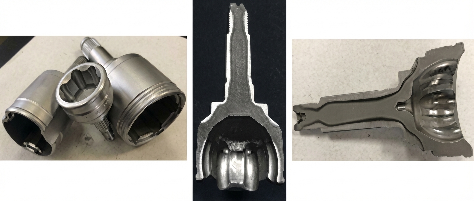
The required heating pattern can be achieved using different induction setups, including scan, single-shot, or static hardening. Coil geometry, power, frequency, and part movement must be selected according to the component geometry and required hardness profile. Complex features such as holes, keyways, and sharp transitions may require additional coil design adjustments to maintain uniform heating and avoid localized overheating.
Induction Tempering After Hardening
As-quenched martensite is often too brittle for industrial service, characterized by low toughness and high residual stresses. Induction tempering is a subcritical process performed below the lower transformation temperature to improve toughness and ductility while relieving internal stresses. Unlike traditional furnace tempering, which can take hours to achieve thermal equilibrium across a batch of parts, induction tempering can achieve results in a shorter timeframe due to direct internal heating at controlled power densities. However, short-time, high-temperature induction tempering should not be assumed equivalent to any arbitrary furnace tempering cycle—temperature-time profiles must be validated for the specific steel grade and required properties.
- Starting condition: Typically as-quenched martensitic microstructure.
- Goal: Reduce brittleness and residual stress while retaining the required hardness.
- Temperature and time: Must be determined by steel grade, prior microstructure, and performance requirements. Temperature ranges commonly fall between approximately 150°C and 650°C.
- Cycle equivalence: Short-time induction tempering cycles are not directly interchangeable with long furnace tempering cycles without validation.
The rapid nature of induction tempering makes it ideal for in-line integration with hardening systems. By minimizing the time between quenching and tempering, the probability of delayed cracking—especially in low-toughness materials—is significantly reduced.
For background on the induction heat-treating metallurgy, understanding phase transformations and microstructural changes is essential for selecting appropriate tempering parameters.
Induction Stress Relieving
Induction stress relieving applies controlled, localized, subcritical heating to reduce residual stresses created by welding, forming, machining, or prior heat treatment. Unlike hardening, it does not normally aim to form martensite or require quenching.
Stress relieving is distinct from tempering in its purpose and starting condition. The table below highlights the key differences:
| Aspect | Induction Tempering | Induction Stress Relieving |
|---|---|---|
| Starting condition | As-quenched martensite | Welded, formed, or machined part with residual stress |
| Primary goal | Reduce brittleness, retain controlled hardness | Reduce residual stress for dimensional stability |
| Re-austenitizing | No (subcritical) | No (subcritical) |
| Quenching required | No | No |
| Typical applications | Hardened gears, shafts, fasteners | Weld seams, pipe ends, machined components |
Induction stress relieving is commonly applied to:
- Weld seams and heat-affected zones: Reducing residual stresses that can lead to cracking or corrosion.
- Pipe ends and upset regions: Preventing issues such as "ring-worm corrosion" in oil country tubular goods (OCTG).
- Machined areas prone to distortion: Stabilizing dimensions after heavy machining operations.
- Locally formed regions: Relieving stresses from bending, forming, or stamping operations.
Key process control parameters for induction stress relieving include:
- Target temperature: Must be selected based on material and stress-relief requirements, typically well below the transformation range.
- Heating rate: Controlled to avoid introducing thermal gradients that could generate new stresses.
- Soak time: Sufficient to allow stress relaxation at the target temperature.
- Temperature uniformity: Maintained across the heated region to ensure consistent stress relief.
- Cooling rate: Controlled to prevent re-introduction of residual stresses.
- Coil coverage: Must encompass the entire stress-affected zone with appropriate overlap.
Advantages
- Localized heating without heating entire structures
- In-line integration capability
- Reduced energy consumption compared to furnace stress relief
- Repeatable and controllable process parameters
Limitations
- Complex thickness variations can cause non-uniform heating
- Geometric transitions may create temperature gradients
- Non-uniform cooling can re-introduce residual stresses
Authoritative industry sources describe induction stress relief as a controlled, locally applicable process that requires material-specific temperature and cooling condition selection (GH Induction). For a more comprehensive treatment of this topic, see our dedicated guide to induction stress relieving.
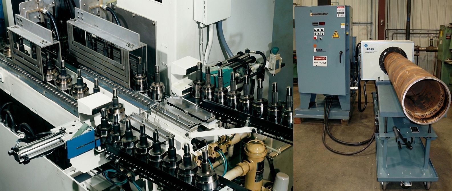
Normalizing and Annealing
Normalizing is a critical pre-treatment used to refine grain structure and homogenize microstructures that have become heterogeneous during primary processing like casting, forging, or rolling. By heating the steel approximately 50°C–100°C above the upper critical transformation temperature (Ac3) and air cooling, a more uniform ferritic/pearlitic structure consisting of equiaxed grains is produced. This homogenization is often recommended before rapid induction hardening to ensure a consistent material response to short austenitization cycles and to minimize final part distortion. Induction is highly effective for normalizing elongated workpieces of small and moderate sizes, such as tubes and rods, where the speed of induction prevents excessive grain growth or decarburization that can occur in longer furnace cycles.
Annealing encompasses several sub-processes, each with specific industrial roles. Full annealing and homogenization involve long soak times—often several hours—to achieve a soft, stress-free state. Because of these long soak requirements, induction heating is generally less cost-effective than gas or resistive furnaces for bulk full annealing. However, induction excels in specialty annealing applications such as bright annealing of stainless steel tubes, where tubes are heated to elevated temperatures and passed through a quench tunnel filled with a controlled atmosphere (typically hydrogen and nitrogen) to prevent surface oxidation. Intercritical annealing, which heats the material between the Ac1 and Ac3 lines, is also possible with induction for applications requiring specific multiphase microstructures, provided the necessary holding times are relatively short.
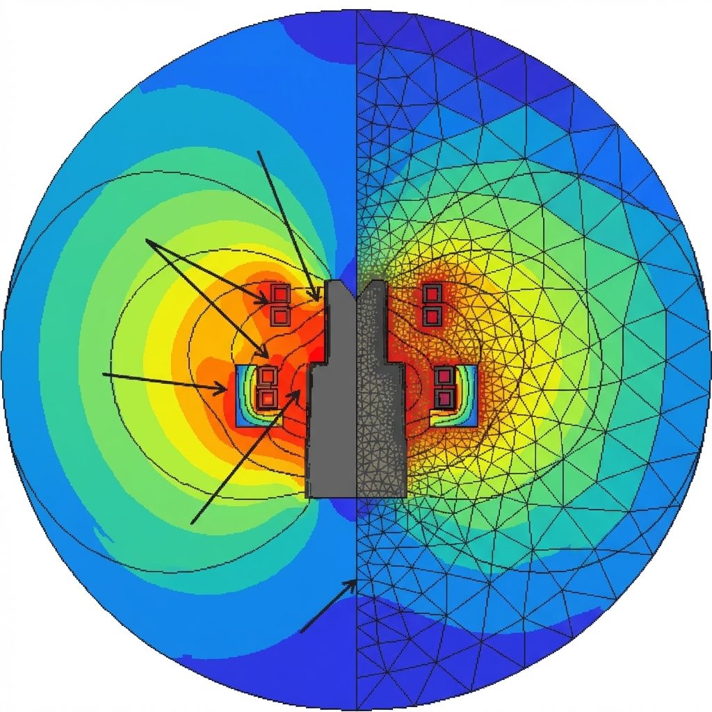
Subcritical annealing, or process annealing, is performed below the transformation temperature to soften cold-worked steels by redistributing dislocations. This is particularly useful for softening the threads of carburized components, where ductility is required for assembly but the high strength and hardness of the remainder of the part must be preserved. Localized thread softening via induction allows for focusing energy precisely on the fillet and thread area while ensuring the neighboring spline or shoulder regions are not re-hardened. This requires precise 3D temperature control and often utilizes flux concentrators and auxiliary thermal influencers, such as Faraday rings or localized spray cooling, to manage the heat-affected zone (HAZ).
How Process Parameters Affect the Result
The outcome of any induction heat treatment process depends on the interplay of multiple parameters. The table below summarizes the primary effects of each:
| Parameter | What It Primarily Affects |
|---|---|
| Frequency | Current penetration depth and heat-source distribution |
| Power density | Heating rate |
| Heating time | Temperature profile and thermal conduction depth |
| Coil geometry / gap | Coupling efficiency and spatial uniformity |
| Material / microstructure | Heating response and hardenability |
| Quench conditions | Martensite formation, distortion, and cracking risk |
Material and Starting Microstructure
The workpiece material determines how it responds to induction heating. Electrical resistivity and magnetic permeability affect eddy current distribution and heating rate. Carbon content, alloying elements, and prior microstructure (e.g., annealed, normalized, or cold-worked) determine hardenability and the resulting phase transformations. For consistent results, the starting microstructure should be uniform—hence the practice of normalizing before hardening.
Frequency, Power Density, and Heating Time
Frequency influences the depth of current penetration, but it is not the sole determinant of case depth. The following ranges are illustrative, not universal specifications, as actual results depend on all parameters listed above:
- 70–600 kHz (high frequency): Generally associated with shallow case depths (approximately 0.25–1.25 mm), suitable for small components like bearings and pins.
- 10–200 kHz (medium frequency): Generally associated with moderate case depths (approximately 1–4 mm), suitable for parts like crankshafts and camshafts.
- 50 Hz–10 kHz (low frequency): Generally associated with deeper hardening (approximately 5–15+ mm), suitable for heavy-duty applications like axle shafts and large sprockets.
For deep-hardening scenarios, a preheating cycle or multiple sequential frequencies can be used to create a thermal gradient that ensures effective austenitization at the required depth while protecting the core. Power density and heating time work together with frequency to determine the final thermal profile—higher power density increases the heating rate, while longer heating time allows heat to conduct deeper into the material.
Accuracy and efficiency can be further enhanced by the "self-quenching" effect (also known as mass quenching) in specific scenarios. When a massive part undergoes shallow surface heating, the cold core acts as a heat sink, conducting heat away from the surface rapidly enough to form martensite without the need for external quenchants. However, for most applications, an integrated quench system is necessary to ensure the cooling rate exceeds the critical velocity required for martensitic transformation across the entire hardened zone.
Coil Geometry and Coupling
The induction coil (inductor) is the component most directly responsible for shaping the energy delivery to the workpiece. Coil geometry—including the number of turns, turn spacing, cross-section, and coupling gap (the distance between the coil and the workpiece)—determines the magnetic field distribution and heating pattern. Tighter coupling improves efficiency but may be limited by part tolerances, thermal expansion, and the need for quench spray clearance. For complex geometries, copper profiling and flux concentrators are used to direct energy where it is needed and prevent unwanted heating of adjacent regions.
Quenching and Cooling
Quenching converts the austenitized region to martensite. The quenchant type (water, polymer solution, or oil), flow rate, pressure, and timing all affect the cooling rate. Too-slow quenching may result in incomplete martensite formation; too-fast quenching can cause cracking or excessive distortion. The quench delay—the time between the end of heating and the start of quenching—must also be controlled, as it affects the temperature gradient at the moment of quenching.
Induction Heat Treatment vs. Furnace Heat Treatment
Both induction and furnace heat treatment have their place in modern manufacturing. The choice depends on the application requirements:
| Factor | Induction Heat Treatment | Furnace Heat Treatment |
|---|---|---|
| Heating method | Internal Joule heating via eddy currents | External radiation and convection |
| Heating speed | Very fast (seconds) | Slower (minutes to hours) |
| Localization | Excellent—specific zones can be targeted | Limited—entire part is heated |
| Integration | In-line, single-piece flow | Batch processing |
| Energy efficiency | High (energy goes into the workpiece, not the surroundings) | Lower for small batches; higher utilization for bulk loads |
| Best for | Localized hardening, tempering, stress relieving, in-line production | Long-soak processes, bulk annealing, through-treatment of large parts |
| Limitations | Complex coil design; less suitable for long soaks | Slower; less precise; higher energy loss |
Induction is well suited to applications requiring localized, repeatable, in-line processing. Furnaces may remain preferable for long-soak treatments (such as full annealing) or bulk processing of large batches where throughput outweighs the need for localization.
Applications and Part Examples
Induction heat treatment is used across a wide range of industries. For a broader view of real-world induction heat-treating applications, the following examples illustrate common use cases:
-
Automotive
Surface hardening of gears, camshafts, crankshafts, transmission shafts, and CV joints. Selective hardening of valve seats and bearing journals.
-
Heavy machinery
Through-hardening of pins, sprockets, and track links for construction and mining equipment.
-
Oil and gas
Stress relieving of welded pipe joints and upset regions in OCTG to prevent corrosion and joint failure.
-
Tube and pipe manufacturing
Continuous normalizing and annealing of welded or seamless tube in production lines.
-
Aerospace
Localized heat treatment of landing gear components, engine parts, and fasteners.
-
General manufacturing
Hardening of hand tools, cutting tools, and machine components; stress relieving of machined weldments.
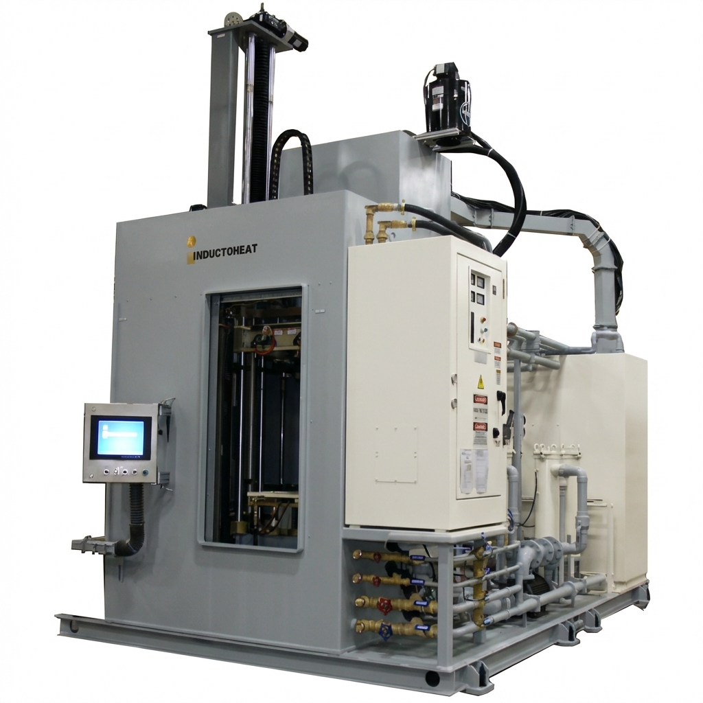
Beyond steel and cast iron, induction heating is also used for nonferrous materials. High-speed induction annealers for copper tubing represent a significant advancement over traditional bell-type or roller hearth furnaces, enabling single-pass annealing and coiling that reduces operating costs and increases throughput. In the munitions industry, induction systems are used for the precise annealing of cartridge cases with high repeatability. However, the ability to focus energy precisely remains the defining advantage of induction heat treatment across the engineering landscape.
Common Defects and Quality-Control Methods
Understanding common defects and how to prevent them is essential for achieving consistent induction heat treatment results:
| Defect | Typical Cause | Prevention / Control |
|---|---|---|
| Cracking | Excessive heating rate, aggressive quench, sharp corners, delayed tempering | Optimize heating rate and quench severity; add radii; temper promptly after quench |
| Distortion | Non-uniform heating or cooling, residual stresses, asymmetric geometry | Improve coil design and coupling; use preheating; control quench uniformity |
| Soft spots | Insufficient heating, quench interference, coil misalignment | Verify temperature uniformity; check coil alignment; ensure adequate quench coverage |
| Overheating / burning | Excessive power or time, inadequate temperature monitoring | Use closed-loop temperature control; validate power-time recipes |
| Insufficient case depth | Wrong frequency, insufficient power or time, poor coupling | Adjust frequency, power, and time; verify coil gap; validate with metallographic sectioning |
| Grain growth | Excessive austenitizing temperature or time | Optimize thermal cycle; consider normalizing before hardening |
Quality-control methods typically include:
-
Hardness testing
Surface and cross-sectional hardness measurements (Rockwell, Vickers, or microhardness) to verify case depth and core properties.
-
Metallographic examination
Sectioning, mounting, polishing, and etching to inspect microstructure, case depth, and phase distribution.
-
Dimensional inspection
Measuring part dimensions before and after treatment to monitor distortion.
-
Crack detection
Magnetic particle inspection (MPI) or dye penetrant testing to detect surface and near-surface cracks.
-
Temperature monitoring
Real-time pyrometry and process data logging for traceability and statistical process control.
FAQ Aboout Induction Heat Treatment
Q1: What makes induction heat treatment different from traditional furnace heating?
Induction heating uses high-frequency electromagnetic fields to generate heat internally within the workpiece through eddy currents, rather than relying on external heat transfer. This allows for rapid, localized heating, enabling single-piece flow production instead of batch processing. The process can selectively harden specific zones while leaving other areas unaffected, something traditional furnaces cannot achieve with the same level of control.
Q2: How do engineers control the depth of surface hardening?
Frequency is an important factor, but final case depth also depends on power density, heating time, coil geometry, material properties, and quench conditions. Higher frequencies (70–600 kHz) generally produce shallower case depths (0.25–1.25 mm). Medium frequencies (10–200 kHz) achieve 1–4 mm depths. Lower frequencies (50 Hz–10 kHz) create deeper hardening (5–15+ mm). These ranges are illustrative, not universal specifications. For deep hardening, engineers may use preheating cycles or multiple sequential frequencies to ensure proper austenitization throughout the target depth.
Q3: Why is tempering necessary after induction hardening?
As-quenched martensite is extremely hard but also brittle with high residual stresses, making it prone to cracking in service. Induction tempering (performed below the lower transformation temperature) restores ductility and toughness while relieving internal stresses. Induction tempering can achieve results in seconds to minutes, allowing immediate in-line processing that reduces the risk of delayed cracking and integrates with modern production lines.
Q4: What is induction stress relieving and when is it used?
Induction stress relieving applies controlled, localized, subcritical heating to reduce residual stresses created by welding, forming, machining, or prior heat treatment. Unlike hardening, it does not aim to form martensite or require quenching. It is commonly used on welds, heat-affected zones, pipe ends, and machined areas prone to distortion.
Q5: What is the difference between induction tempering and induction stress relieving?
Tempering starts from as-quenched martensite and aims to reduce brittleness while retaining controlled hardness. Stress relieving starts from a part that has residual stresses from welding, forming, or machining, and aims to reduce those stresses without intentionally re-austenitizing the material. Both operate below the transformation range, but their purposes, starting conditions, and temperature-time cycles differ.
Keep Learning
Induction Heat Treatment: Hardening, Tempering & Stress Relief
Induction heat treatment is a heat treatment process that uses an alternating electromagnetic field to generate heat inside an electrically conductive workpiece. It enables manufacturers to selectively heat specific areas of a component for processes such as hardening, tempering, annealing, and stress relieving, rather than heating the entire part in a furnace. This localized heating makes induction particularly useful for applications that require controlled case depth, repeatable results, and integr......
A Complete Guide to Resistive Heating Elements: How They Work, Types, Materials, and Applications
A resistive heating element converts electrical energy into heat as electric current passes through a material with electrical resistance. This process is known as Joule heating, and its electrical power can be expressed as P = VI = I²R = V²/R. Common forms include resistance wire, heating plates, tubular and cartridge heaters, strip and tape heaters, ceramic heaters, and flexible etched-foil heaters. The right heating element depends on more than its shape. Operating temperature, voltage, required po......