
Induction Heat Treating Applications in the Real World: What the Process Looks Like Across Parts
14 min
- Induction Heat Treating: From Theory to Production Reality
- 1. Gear and Pinion Hardening: Localized Precision
- 2. Crankshaft Hardening: Solving Geometry Roadblocks
- 3. Camshafts: Controlling the Lobes
- 4. Raceway Hardening: Managing the Soft Band
- 5. Production-Minded Considerations for Porting Applications
- FAQ about Induction Heat Treating Applications
Key Takeaways
Application-Specific Design: Induction heat treating is not one-size-fits-all—coil geometry, frequency, and handling must be tailored to each part type, from gears and crankshafts to camshafts and raceways.
Localized Precision Over Furnace Methods: Induction hardening targets only the areas requiring metallurgical change, dramatically reducing distortion and cycle time compared to traditional carburizing.
Non-Rotational Technology (SHarP-C): Stationary hardening eliminates crankshaft rotation during processing, cutting heat time by 3–4x and reducing distortion to under 45 microns.
Soft Band Elimination: Dual-inductor scanning technology enables seamless 360° raceway hardening for critical applications like wind turbine bearings.
Production Robustness: CNC-machined solid copper inductors outperform brazed joints in high-volume environments, exceeding 150,000 cycles with consistent sub-millimeter air gaps.
Induction Heat Treating: From Theory to Production Reality
In the transition from theoretical induction heating (IH) principles to production-floor reality, the "ideal" process quickly meets the complex constraints of part geometry, handling logistics, and quenching requirements. Induction heat treating (IHT) is not a one-size-fits-all solution; the approach for a 3-meter wind turbine gear bears little resemblance to the high-speed hardening of an automotive transmission spline. For engineers, understanding these application-specific nuances is critical when porting a process from one component class to another.
This survey examines the real-world application of IHT across gears, crankshafts, camshafts, and raceways. We will break down how the coil approach, frequency selection, and handling mechanisms adapt to meet stringent metallurgical and geometric tolerances in a production environment. Beyond the basic physics, we look at the pragmatic reasons—cycle time reduction, localization, and distortion control—that drive manufacturers to choose induction over traditional furnace-based methods like carburizing.
1. Gear and Pinion Hardening: Localized Precision
Traditional gear heat treatment typically involves gas carburizing for extended periods—often exceeding 30 hours for large components—followed by oil quenching. While effective, this process heats the entire component, leading to significant thermal expansion and subsequent contraction, which manifests as distortion. In contrast, induction hardening allows for localized heating, targeting only the areas where metallurgical changes are desired—such as the flank, root, and gear tip. This selective hardening not only optimizes performance but also minimizes distortion by leaving the bulk of the gear body unaffected by high temperatures.
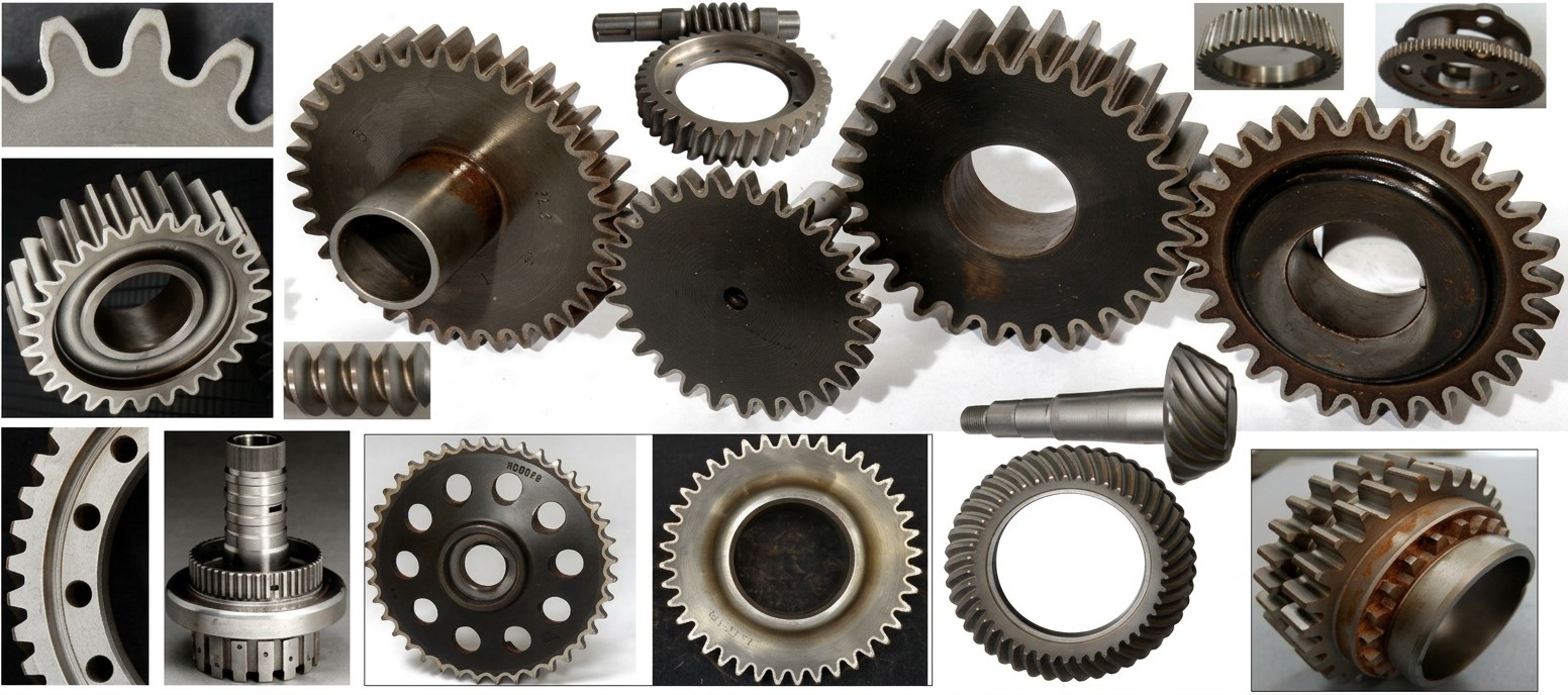
Figure 1: Induction hardening is applied across a vast range of geometries, including spur, helical, worm, and internal gears.
Hardness Patterns and Operating Loads
Specifying the required hardness profile is the first step in system design. Common misconceptions suggest that a uniform contour profile is always best, but the reality depends on the load conditions—whether occasional, intermittent, or continuous. Continuous loads (10 to 24 hours per day) demand different fatigue resistance than occasional loads (under 30 minutes per day). Different patterns provide specific mechanical advantages:
- Flank Hardening: Focuses on wear resistance. Historically used for large sprockets, this pattern ends before the root fillet. Engineers must be cautious, as this can shift tensile residual stresses to the root land, potentially reducing bending fatigue strength by up to 25% compared to non-hardened parts.
- Root Hardening: Reinforces the tooth fillet area where maximum bending stresses occur. By shifting tensile residual stresses away from the surface, it significantly improves fatigue resistance.
- Profile (Contour) Hardening: Often the "gold standard," providing an uninterrupted layer of compressive stresses across the entire tooth perimeter. This ensures consistent wear resistance at the pitch line and high strength at the root.
Design Note
Production engineers must be wary of through-hardening small teeth. While it ensures high surface hardness, it can introduce brittleness. A ductile core (typically 30 to 44 HRC) combined with a hard surface (56 to 62 HRC) offers the best balance of wear resistance and toughness for shock loads. Excessive through-hardening risks brittle fracture under impact loading, a common failure mode in heavy-duty transmission gears.
Coil Approach: Spin vs. Tooth-by-Tooth
The choice of coil design is primarily driven by gear size, production rate, and available power. Spin hardening utilizes encircling inductors, heating the whole gear at once. This offers maximum production throughput but requires massive power densities to suppress thermal conduction into the core. For example, a medium-sized gear might require hundreds of kilowatts for just a few seconds of heat time to achieve a crisp contour.
Production Pacing: Handling Methods
- Spin Hardening: Best for high volumes of small/medium gears. Rotation during heating is mandatory to compensate for field fringing effects and ensure circumferential uniformity.
- Tooth-by-Tooth (Gap-by-Gap): The preferred method for large gears (e.g., wind turbine components >3m). While it reduces power demand by heating only one gap at a time, it increases cycle times and requires sophisticated tracking systems to maintain tight air gaps (0.8 to 2 mm).
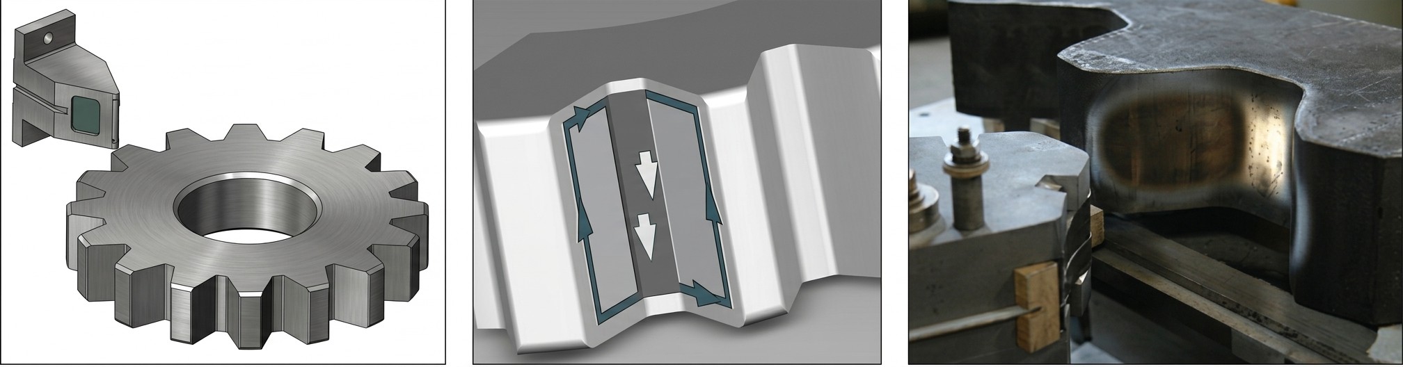
Figure 2: The "butterfly" inductor used in gap-by-gap hardening targets the root area, with eddy currents looping through the flanks.
In gap-by-gap hardening, engineers must manage the "temper back" effect. As one tooth is heated, thermal conduction can soften the previously hardened adjacent tooth, particularly at the thin tooth tip. Integrated spray quench blocks or even submerged quenching in a temperature-controlled tank are common production strategies to protect existing martensitic structures during the multi-revolution process. Submerged hardening, while complex to set up, offers the benefit of instantaneous quenching and additional cooling for the inductor itself.
Mini-Case: Wind Turbine Yaw Gears
Large yaw gears used in wind turbines, often exceeding 2 meters in diameter, present a classic "gap-by-gap" case. Using spin hardening would require power supplies in the megawatt range, which is rarely feasible. By employing a "butterfly" style scanning inductor, the power requirement is kept to roughly 100–200 kW. The primary constraint is the multi-hour cycle time. To prevent temper-back on previously hardened teeth, auxiliary cooling nozzles are positioned to spray the adjacent teeth while the inductor traverses the current gap. This maintains the root hardness at the required 55–59 HRC without softening the flank contact area of the neighboring tooth.
2. Crankshaft Hardening: Solving Geometry Roadblocks
Crankshafts present a unique challenge: the irregular presence of counterweights prevents the use of simple encircling coils. Historically, this forced engineers into complex rotational technologies where U-shaped inductors "ride" on the journal during rotation. The goal of induction here is two-fold: wear resistance on the bearing journals and fatigue strength in the fillets. Depending on the design, manufacturers use either band hardening (journal surface only) or band-and-fillet hardening (surface plus the radius).
The Rotational Dilemma
Rotational technology uses U-shaped (half-shell) inductors that physically contact the journal using carbide guides. As the crankshaft rotates, the inductor follows the orbital motion of the pins. While industry-standard for decades, this approach carries heavy maintenance baggage. Carbide guides wear down, leading to air-gap variations and pattern drift. In high-volume settings, the maintenance cost can reach $2 per crankshaft, with coils rarely exceeding 70,000 cycles due to stress-corrosion cracking and joint fatigue. Furthermore, the non-symmetrical heating (only 35–40% of the journal is under the coil at any moment) requires longer heat times (8–18 seconds), leading to deeper heat penetration and greater distortion.
The Non-Rotational (SHarP-C) Revolution
A more modern production approach involves stationary hardening (SHarP-C technology). This uses a "passive-active" coil design where the inductor encircles the journal 100% without rotation. By eliminating movement, the system achieves a three- to fourfold reduction in heat time (down to 2.5–4 seconds). The result is a dramatic reduction in distortion—often less than 45 microns—which minimizes or eliminates the need for aggressive post-process straightening. Straightening is a high-risk operation that can introduce cracks or redistribute residual stresses in the critical fillet areas.
Mini-Case: V6 Automotive Crankshafts
In a high-volume automotive line producing 90 V6 crankshafts per hour, the switch from rotational to SHarP-C technology highlights the impact of cycle time. The rotational system required 15 seconds per journal and significant maintenance downtime for carbide guide replacement every few shifts. The SHarP-C system reduced the heat time to 3.5 seconds. By using CNC-machined solid copper blocks instead of brazed joints, coil life exceeded 150,000 cycles. Most importantly, the reduction in energy consumption (up to 20%) and the near-elimination of straightening operations saved the manufacturer an estimated $200,000 annually in energy and scrap costs.
3. Camshafts: Controlling the Lobes
Camshaft lobes are eccentrically shaped, meaning the "nose" of the cam is coupled much more tightly to a conventional coil than the "heel" (base circle). This proximity effect naturally generates more heat at the nose, risking overheating or cracking before the heel reaches austenization temperature. Since the nose experiences the highest contact pressure with the valve follower, obtaining a deep, uniform case is critical to prevent pitting and spalling.
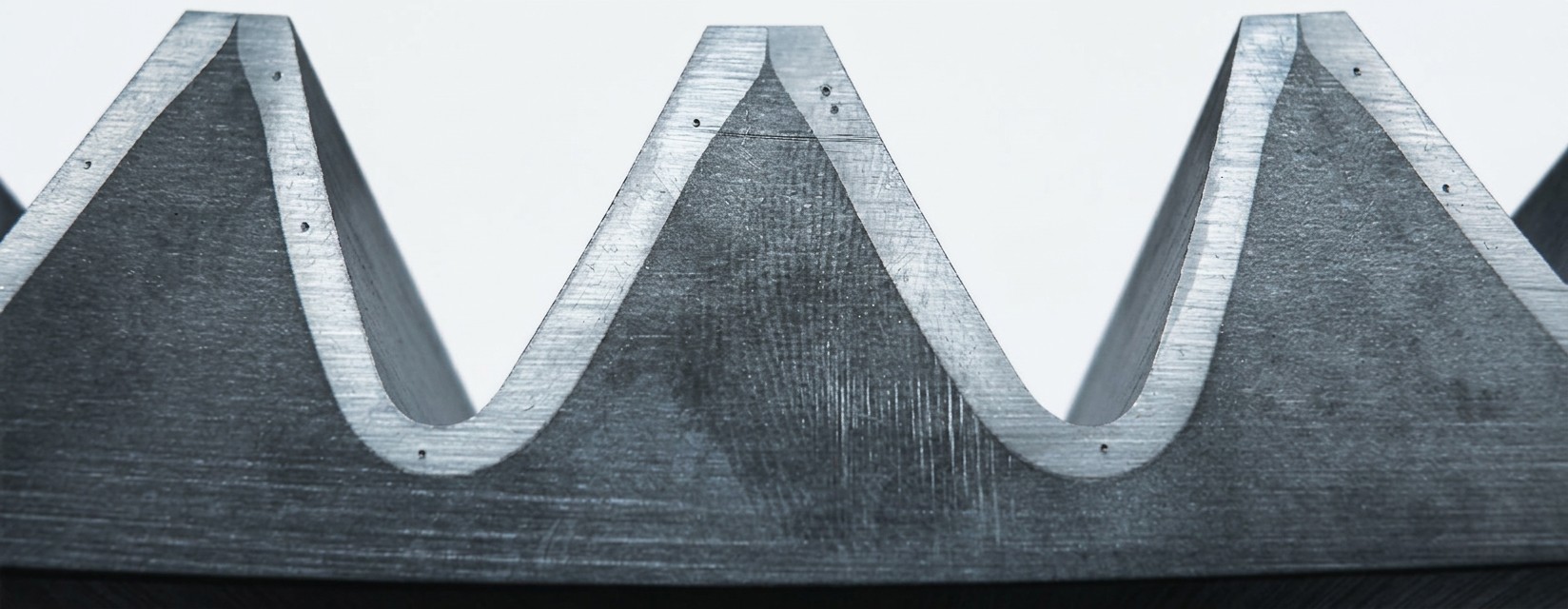
Figure 3: Cross-sectional analysis showing the hardened case depth following the contour of the part.
To achieve a true contour pattern, engineers must employ specific strategies to balance the temperature across the irregular geometry:
- Scanning Mode: Useful for low production or large lobes. It allows the inductor to traverse the lobe width while varying power and speed, providing precise control over the axial heat affected zone (HAZ).
- Single-Shot with Profiling: For automotive volumes, multiturn coils are used with profiled copper faces. The coil is often "decoupled" (positioned further away) from the nose to prevent overheating while ensuring the heel reaches the critical temperature.
- Stationary SHarP-C: Similar to the crankshaft approach, this uses a split-inductor design that "locks" the pattern in place, achieving undetectable distortion (3–5 microns) and fine-grain martensitic structures.
Mini-Case: Heavy-Duty Truck Camshafts
A manufacturer of forged steel truck camshafts faced issues with "nose cracking" during high-frequency single-shot hardening. The tight coupling at the cam nose led to localized overheating and excessive grain growth. By switching to a lower frequency (approx. 10 kHz) and a profiled inductor that increased the air gap at the nose by 1.5 mm relative to the heel, the thermal gradient was neutralized. This "decoupled nose" approach ensured the entire profile reached 900°C simultaneously. The result was a uniform 3 mm case depth across the nose and heel, eliminating the scrap rate previously caused by quench cracks at the cam tips.
4. Raceway Hardening: Managing the Soft Band
Medium and large-sized bearing raceways, such as those used in wind energy or heavy machinery, are hardened using either single-shot or scanning processes. Single-shot hardening for rings can be applied to the inside diameter (ID) or outside diameter (OD) by spinning the ring inside or around the inductor. However, for very large rings (up to 3.5 meters), scanning is the only economical choice.
The primary constraint in raceway scanning is the "soft band" or transition zone. This occurs at the end of the circular scan where the inductor must stop heating. The final section to be heated inevitably tempers back the start of the hardened path. In traditional scanning, this soft band is a necessary compromise, often positioned in a low-load area of the bearing housing.
Mini-Case: Seamless Wind Turbine Bearings
For wind turbine main bearings, a soft band is unacceptable due to the extreme 360-degree loading. To solve this, "seamless" hardening technology is used. This employs two independent inductors that scan in opposite directions, each covering nearly 180 degrees. At the end of the scan, the two inductors meet. Because their magnetic fields complement each other at the final heating position, and an auxiliary quench is applied simultaneously, the soft band is eliminated. This process allows the production of 3.5-meter bearing rings weighing over 5,000 kg with a perfectly uniform 3 mm case depth around the entire perimeter.
5. Production-Minded Considerations for Porting Applications
When moving an IHT process from one part style to another, several production-critical variables must be reconsidered. The interaction between frequency, power density, and the prior microstructure of the steel determines the speed and quality of the response.
| Factor | Engineer's Watch-list |
|---|---|
| Frequency Selection | High frequency (e.g., 300 kHz) follows contours but risks overheating tips. Low frequency (10 kHz) penetrates deeper and follows the root circle, better for heavy-load gears. |
| Power Density | Excessive power density can saturate steel, increasing the skin depth (δ) and shifting heat intensity from tips to roots. Must be balanced against heat time to control distortion. |
| Quench Technique | Moving from integrated quench (small parts) to large rings may require separate concentric quench blocks or submerged tanks to prevent softening of adjacent zones via conduction. |
| Material Microstructure | Fine-grained Q&T structures (30–36 HRC) respond fastest. Spheroidized microstructures require longer times and higher temperatures, risking grain growth and distortion. |
| Part-to-Part Spacing | Proximity of lobes or teeth affects magnetic field fringing. Use flux concentrators (laminations) to "shield" adjacent features and prevent temper-back. |
The Distortion Trade-off
Distortion is the ultimate metric for process success. In any elongated product like a steering rack or camshaft, the heating cycle tends to cause bowing and growth. Non-rotational technology consistently offers lower and more predictable distortion than rotational or furnace-based methods. By targeting only the required surface layer and using extremely short heat times (often under 4 seconds), the unaffected "cold" mass of the part serves as a shape stabilizer. This "cold core" resists the expansion forces of the heated surface, maintaining the axial straightness of the component.
For the production engineer, the goal is "verifiable repeatability." Advanced monitoring of energy input, quench flow, and heat time is standard, but the physical robustness of the inductor itself—moving away from brazed joints toward CNC-machined solid copper blocks—is what ensures a process stays within spec over hundreds of thousands of cycles. Brazed joints are prone to fatigue and leaks in high-volume environments, whereas solid-block inductors provide the rigidity needed to maintain sub-millimeter air gaps consistently.
FAQ about Induction Heat Treating Applications
Q: Why is induction hardening preferred over traditional carburizing for gears?
Induction hardening heats only specific areas (flank, root, tip) rather than the entire component, which dramatically reduces distortion and cycle time. Traditional carburizing can take over 30 hours for large gears and causes significant thermal expansion throughout the part. Induction hardening achieves localized precision while maintaining a ductile core, offering better control over the final hardness pattern.
Q: What's the difference between spin hardening and tooth-by-tooth hardening for gears?
Spin hardening uses encircling inductors to heat the entire gear simultaneously, offering maximum throughput for small to medium gears but requiring massive power (hundreds of kilowatts). Tooth-by-tooth (gap-by-gap) hardening heats one tooth gap at a time, reducing power requirements to 100–200 kW, making it ideal for large gears like 3-meter wind turbine components. The trade-off is longer cycle times and the need to manage "temper back" effects on adjacent teeth.
Q: How does non-rotational (SHarP-C) technology improve crankshaft hardening?
Non-rotational technology eliminates the need for the crankshaft to rotate during hardening, reducing heat time from 8–18 seconds to just 2.5–4 seconds. This results in distortion under 45 microns (compared to much higher with rotational methods), often eliminating the need for risky straightening operations. It also extends coil life beyond 150,000 cycles and reduces energy consumption by up to 20%.
Conclusion: Induction Heat Treating Applications
The diversity of induction heat treating applications demonstrates that success lies in the synergy of electromagnetic design and mechanical handling. Whether it is managing the "butterfly" current loops in a gear root or eliminating soft spots in a wind turbine raceway through dual-inductor scanning, the process must be tailored to the part. As you port these technologies, remember that frequency, power density, and quench timing are your primary levers for controlling the final metallurgical outcome. Induction is not just a heating method; it is a precision engineering tool that, when applied correctly, offers unmatched throughput and quality in the modern shop floor.
Keep Learning
How Transparent Graphene Heaters Clear Fogged Glass
Key Takeaways Atom-thin transparency: A single graphene layer transmits about 97.7% of visible light, while five stacked layers still pass roughly 87.3%, making the heater nearly invisible on glass or plastic. Fast, controllable heating: A monolayer device reaches its target temperature with a thermal time constant of only about 6–7 seconds, and input power can be adjusted to hold temperatures from 38 °C up to around 80 °C. Efficiency advantage: Graphene heaters achieved higher temperatures at the sam......
Process Control, Monitoring, and Quality Assurance in Induction Heating: Reducing Risk Without Cutting Every Part
Key Takeaways Separate control from monitoring: A control system executes the recipe; a monitoring system independently verifies what actually happened. Independence turns logs into evidence. Monitor intermediate variables: You can't measure fatigue strength inline, but you can measure delivered kW, frequency stability, position, and quench variables—then compare each cycle to a validated "good envelope." Signature monitoring beats single thresholds: Time-series signatures capture ramps, holds, and tr......
Cooling Induction Power Supplies: Designing the Thermal System That Protects Your Electrical System
Key Takeaways Cooling is a first-class subsystem: Many "electrical" failures in induction lines are actually thermal problems—drifting water temperature, clogged filters, or unbalanced branch flow. Measure at the branch, not the header: A healthy header can mask a starved branch. Branch flow to the highest-loss modules is the single most useful cooling measurement. Trend cooling like a process variable: Baseline flow, temperature, and filter pressure drop during commissioning, then trend them to turn ......
Independent Frequency and Power Control in Induction Inverters: Turning Frequency Back Into a Process Variable
Key Takeaways Frequency as a process variable: Independent frequency and power control decouples resonance supervision from kW regulation, letting engineers set frequency based on process physics rather than control mechanics. Measurable validation: Prove independent control with three commissioning tests—fixed-frequency power steps, fixed-kW frequency sweeps, and coupling variation stability. Production consistency: Stable frequency improves recipe portability, reduces hidden process changes, and mak......
Simultaneous Dual-Frequency Induction Heating: When One Frequency Forces the Wrong Compromise
Key Takeaways One frequency, one compromise: When geometry demands both deep bulk heating and controlled surface gradients simultaneously, a single frequency forces an unacceptable trade-off—dual-frequency widens the process window. Give each channel a role: Assign the lower frequency to bulk penetration and the higher frequency to surface shaping. Structured recipe development follows naturally from this separation. Validate with metrics, not opinions: Dual-frequency is justified only when controlled......
Power Supplies by Application Family: Joining, Mass Heating, and Strip Processing
Key Takeaways Joining operations (brazing, soldering, bonding) demand higher frequencies and matching flexibility to handle variable coil coupling and precision surface heating. Mass heating lines (billets, bars, slabs) prioritize continuous duty, efficiency, and ruggedness at high power levels with multi-coil zone control. Strip processing requires architectures that separate control electronics from high-frequency inverter modules to cope with harsh installation environments. Specifying only kW and ......