The Engineer's Guide to Induction Brazing and Soldering
13 min
- Introduction to Induction Joining
- Defining the Technical Boundary: Brazing vs. Soldering
- Joint Design and Clearance Control
- The Physics of Capillary Flow
- The Induction Equipment Stack
- Strategic Advantages Over Traditional Methods
- Atmosphere and Vacuum Options
- Navigating the Process Window: Do’s and Don’ts
- Filler Materials and Flux Selection
- The Engineer’s Production Checklist
- FAQ about Induction Brazing and Soldering
Key Takeaways
Temperature is the Defining Boundary: Soldering uses fillers melting below 450°C, while brazing uses fillers above 450°C — a threshold that marks a fundamental shift in bond depth, diffusion behavior, and joint strength.
Joint Clearance is Critical: The optimal gap for capillary filler flow is 0.05–0.13 mm at brazing temperature. Engineers must pre-calculate “hot gaps” to account for differential thermal expansion between dissimilar materials.
Induction Offers Unmatched Precision: Compared to torch or furnace methods, induction heating localizes energy within the part itself via eddy currents, minimizing thermal distortion, reducing oxidation, and enabling repeatable, data-driven production.
Process Window Management is the Key to Quality: Achieving a defect-free joint requires disciplined control of temperature ramp rate, dwell time, flux activity, and filler flow — all within a narrow process window.
Surface Preparation is Non-Negotiable: Flux is not a cleaning agent. Parts must be chemically clean before flux is applied; any contamination is the primary cause of joint failure.
Introduction to Induction Joining
In the landscape of modern manufacturing, the ability to create strong, permanent, and reliable metallurgical bonds between metallic components is a fundamental requirement. Among the various joining techniques available to engineers, induction brazing and soldering stand out as exceptionally versatile and efficient processes. These methods leverage electromagnetic induction to generate localized heat, offering significant advantages over traditional torch or furnace-based heating. Whether you are joining complex aerospace assemblies, automotive heat exchangers, or high-capacity electrical components, understanding the nuances of induction-based joining is critical for optimizing both joint quality and production throughput.
At its core, the induction joining process involves heating a joint assembly to a temperature that allows a filler metal to melt and flow into the gap between base components without melting the base materials themselves. This requires a precise “process window” where the temperature is high enough to liquefy the filler but low enough to maintain the structural integrity and metallurgical properties of the workpieces. By utilizing high-frequency alternating currents, induction systems can target energy precisely where it is needed, minimizing the thermal impact on the rest of the assembly.
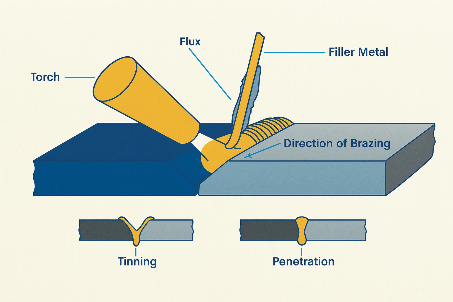
Basic mechanics of the joining process showing filler flow and penetration into the joint gap.
Defining the Technical Boundary: Brazing vs. Soldering
While the terms “brazing” and “soldering” are often used interchangeably in casual conversation, they are distinguished by a clear technical boundary in the engineering world. This boundary is primarily defined by the melting temperature of the filler material used in the process. According to industry-accepted standards, the transition point is 450°C (840°F). If the filler material melts below this temperature, the process is classified as soldering; if it melts above 450°C, it is considered brazing. This temperature threshold is not arbitrary; it marks a transition in the metallurgical behavior of the joint interface.
Beyond the simple temperature threshold, there are significant metallurgical differences between the two processes. In soldering, the reaction between the liquid filler and the base metal is relatively shallow, typically occurring within a depth of only a few micrometers. In contrast, brazing involves much higher temperatures, which facilitate a more aggressive diffusion-type chemical reaction, allowing the filler and base metal to form solid solutions that propagate to a much greater depth. The resulting joint in a brazing operation is often as strong as, or even stronger than, the base materials themselves.
| Definition | |
|---|---|
| Soldering | Joining process where the filler material melts at a temperature below 450°C (840°F). |
| Brazing | Joining process where the filler material melts at a temperature above 450°C (840°F). |
| Metallurgical Bond | The atomic-level bond formed at the interface between the filler and base metal through diffusion and chemical reaction. |
| Liquidus/Solidus | The temperature points at which an alloy is completely liquid or completely solid, respectively. |
Joint Design and Clearance Control
The geometry of the joint is the single most important factor in determining the mechanical integrity of the final assembly. Engineers typically choose between two fundamental designs: the butt joint and the lap joint. A butt joint involves two pieces butted up against each other, offering a flush surface that is aesthetically pleasing but limited in strength. In contrast, a lap joint overlaps the two pieces, providing a significantly larger surface area for the filler metal to bond. This overlapping area — often recommended to be 3 to 6 times the thickness of the thinnest member — ensures that the joint can withstand stresses that might otherwise fail a simple butt joint.
For any joint design to succeed, clearance control is paramount. Capillary action — the force that draws molten filler into the joint — is highly dependent on the gap between mating surfaces. If the gap is too small (typically less than 0.03 mm), there is insufficient space for the filler to flow. If the gap is too large (exceeding 0.25 mm for many alloys), the capillary force weakens, leading to voids and incomplete penetration.
Note
Engineers must account for thermal expansion during the heating cycle. Materials with different coefficients of thermal expansion (CTE) will cause the joint gap to open or close as the assembly reaches brazing temperature. A clearance that appears perfect at room temperature may become dangerously tight or excessively wide at 800°C, necessitating careful pre-calculation of the “hot” gap.
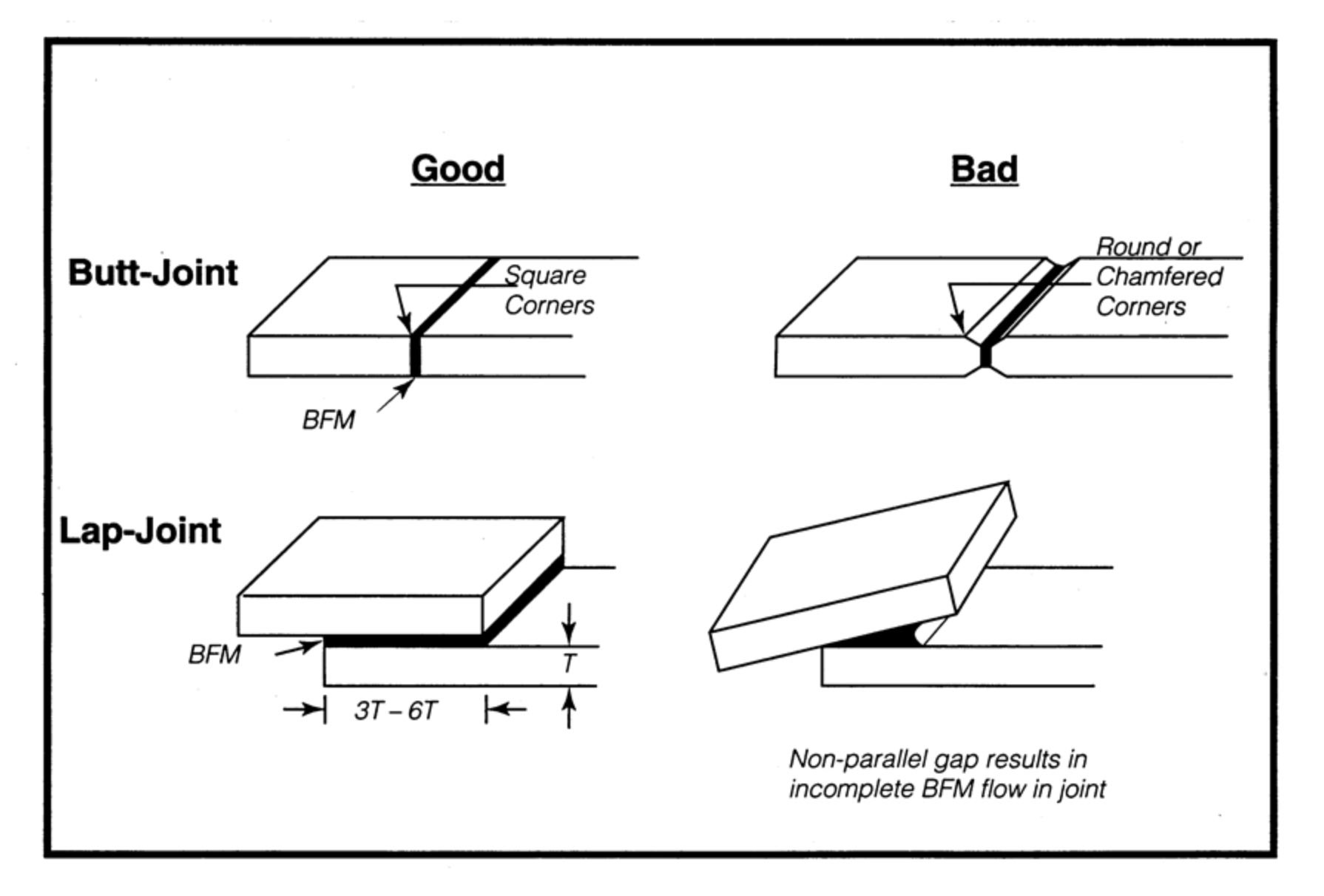
Comparison of good and bad joint design practices, highlighting the importance of square corners and parallel gaps.
The Physics of Capillary Flow
The success of an induction joint relies on the fluid dynamics of the molten filler material. Unlike welding, where base metals are fused, brazing and soldering depend on the “wetting” characteristics of the filler. When the joint area reaches the appropriate temperature — exceeding the filler’s melting point but remaining below the base metal’s liquidus point — the filler liquefies and is drawn into the joint gap through a combination of capillary action and gravitational force. Wetting is essentially the ability of a liquid to maintain contact with a solid surface, resulting from intermolecular interactions when the two are brought together.
For capillary action to be effective, the joint surfaces must be chemically clean and the temperature must be uniform across the entire interface. If one side of the joint is significantly hotter than the other, the filler will tend to flow toward the hotter surface, leading to uneven distribution and “starved” areas in the joint. This is a common challenge when joining dissimilar metals or components with vastly different masses. The induction coil must be designed to compensate for these differences, ensuring both sides of the interface reach the flow point of the filler simultaneously.
The Induction Equipment Stack
Implementing a successful induction brazing or soldering operation requires a coordinated stack of specialized equipment. Each component plays a vital role in ensuring the precision and repeatability of the thermal cycle:
Power Supply (Inverter)
Converts line frequency to the high frequency (typically 10 kHz to 400 kHz) required for the application. Modern solid-state inverters allow for precise control over power delivery.
Induction Coil (Inductor)
Custom-designed copper tubing that conforms to the joint geometry to deliver electromagnetic energy. The coil design determines the heating pattern and efficiency.
Water-Cooling System
Essential for maintaining the temperature of the induction coil and the internal components of the power supply, which can generate significant heat during operation.
Fixturing and Tooling
Positions and holds the components in the correct orientation relative to the coil. These must be made of non-conductive or nonmagnetic materials to avoid parasitic heating.
Filler Material and Flux
The consumables that form the joint. Flux protects the surfaces from oxidation, while the filler — often in the form of wire, paste, or preforms — creates the metallurgical bond.
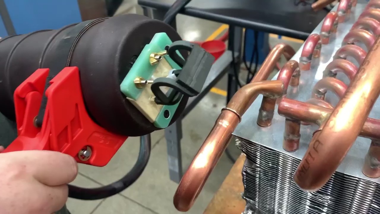
Industrial induction joining environment showing the complexity of fixturing and assembly.
Strategic Advantages Over Traditional Methods
Advantages of Induction Joining
- Localized heating: Heat is generated within the part itself via eddy currents, focused strictly on the joint area, resulting in less thermal distortion and reduced oxidation.
- Exceptional repeatability: Eliminates the “art” of torch brazing, replacing operator variability with a data-driven industrial process.
- Faster cycle times: Cycle times measured in seconds vs. hours required for furnace brazing.
- Piece-to-piece processing: Only the bond area is heated, protecting heat-sensitive components — critical in electronics and medical device manufacturing.
- Safer work environment: Fewer toxic fumes and less radiant heat exposure for operators.
- Automation-ready: Easily integrated into automated production lines.
Atmosphere and Vacuum Options
While the majority of induction brazing occurs in open air with the aid of flux, certain high-purity or reactive metal applications require controlled environments. Induction coils can be placed within gas-tight chambers filled with inert gases like Argon or reducing atmospheres such as Hydrogen-Nitrogen mixtures. These environments prevent the formation of surface oxides, often eliminating the need for flux entirely.
Vacuum chambers are also an option for critical aerospace or semiconductor components, though they generally introduce more complexity and are less suited for high-volume production compared to atmospheric systems. Controlled atmospheres are also beneficial for preventing the “flux inclusion” defects that can occur in high-reliability joints.
Navigating the Process Window: Do’s and Don’ts
Achieving a high-quality joint is a delicate balancing act of time and temperature, often visualized as a “process window.” The goal is to reach a uniform temperature across both sides of the joint that exceeds the filler’s flow point for a specific “dwell time,” allowing for complete capillary saturation. If the heat time is too short, the filler may not reach its flow point, or the flux may not have sufficient time to dissolve surface oxides. Conversely, excessive time or temperature can lead to “flux burnout,” where the protective agent evaporates or loses its chemical activity.
The Process Window: Engineering Best Practices
DO
- Reach a uniform temperature on both mating parts simultaneously to ensure balanced filler flow.
- Use a short “dwell time” once the flow temperature is reached to allow full capillary penetration without excessive grain growth.
- Monitor the process using closed-loop temperature control (IR sensors) to compensate for variations in part positioning or coil coupling.
DON’T
- Overheat the joint. Excessive temperature can cause the filler metal to “boil” or alloy too aggressively with the base metal, leading to brittle intermetallics.
- Allow the flux to sit at high temperatures for too long. Flux has a finite life; once it “burns out,” the joint will oxidize rapidly, resulting in poor wetting and voids.
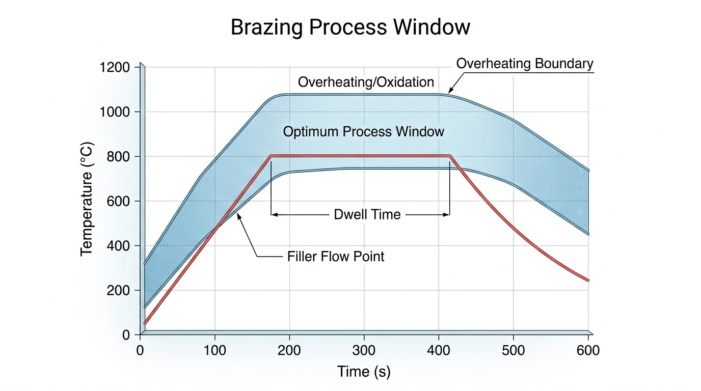
The optimum process window defines the ideal temperature-time profile to avoid both underheating and oxidation.
Filler Materials and Flux Selection
The choice of filler material and flux is as critical as the induction coil design. Hundreds of filler alloys are available, ranging from low-temperature tin-lead and lead-free solders to high-temperature silver, copper, and nickel-based brazing alloys. Selection factors include the physical and mechanical properties required, the melting characteristics (liquidus and solidus points), and the form of the filler. Fillers can be applied as wire, paste, or precisely stamped preforms. Preforms are particularly popular in automated induction joining because they provide a measured volume of filler metal that can be placed exactly where it is needed before the heating cycle begins.
Fluxes serve the vital role of dissolving surface oxides and preventing new oxides from forming during the heating cycle. However, flux is not a cleaning agent; it cannot remove heavy grease, oil, or scale. Parts must be chemically or mechanically cleaned before flux is applied. The flux must be active at a temperature slightly below the melting point of the filler and must remain stable until the filler has flowed and solidified. Upon completion of the joint, residual flux must typically be removed — often with hot water — to prevent long-term corrosion of the assembly.
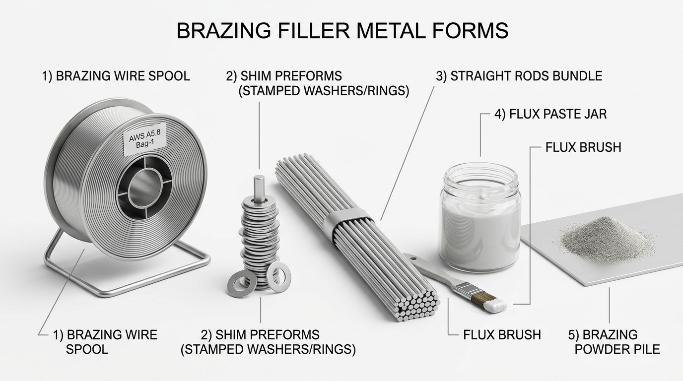
Common forms of brazing filler metal and flux used in industrial induction applications.
The Engineer’s Production Checklist
To ensure repeatability in a production environment, engineers should follow a rigorous preparation and execution protocol. Contaminants are the primary cause of joint failure, so surface preparation must be the first priority. The following checklist highlights the critical variables that must be managed for every induction brazing or soldering cycle to ensure high-yield manufacturing.
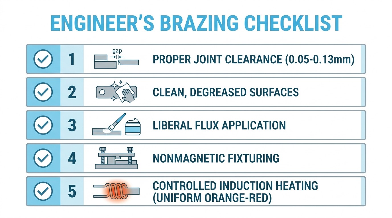
Summary of the critical steps for achieving a successful induction-brazed joint.
1Surface Preparation
Parts must be degreased and free of scale or heavy oxidation. A chemically clean surface is required for proper filler wetting.
2Joint Clearance Verification
Confirm that clearances are within the 0.05–0.13 mm range at brazing temperature, accounting for differential thermal expansion between dissimilar materials.
3Flux Application
Apply flux liberally to both mating surfaces just before heating. Ensure the flux covers the entire interface to provide full protection during the ramp-up phase.
4Nonmagnetic Fixturing
Use fixtures made of ceramics, stainless steel, or high-temp plastics to prevent parasitic heating of the tooling, which wastes energy and can cause fixture failure.
5Thermal Uniformity
Monitor the joint area to ensure both base components reach the target temperature simultaneously. Use IR sensors or thermocouples for closed-loop control to maintain the process window.
FAQ about Induction Brazing and Soldering
Q: What's the difference between brazing and soldering?
A: The key distinction is temperature. Soldering uses filler materials that melt below 450°C (840°F), while brazing uses fillers that melt above this threshold. Beyond temperature, brazing creates deeper metallurgical bonds through aggressive diffusion reactions, often producing joints as strong as the base materials. Soldering creates shallower bonds, typically only a few micrometers deep, with intermetallic phases at the interface.
Q: Why is joint clearance so critical for successful brazing?
A: Capillary action — the force that draws molten filler into the joint — depends heavily on the gap between mating surfaces. If the gap is too small (less than 0.03 mm), filler cannot flow properly. If it's too large (over 0.25 mm), capillary force weakens, causing voids and incomplete penetration. The optimal range is typically 0.05–0.13 mm at brazing temperature. Engineers must also account for thermal expansion, as materials expand differently when heated, changing the gap size during the heating cycle.
Q: What are the main advantages of induction joining over torch or furnace methods?
A: Induction offers three major advantages: precise heat localization (minimizing thermal distortion and protecting heat-sensitive components), exceptional repeatability (eliminating operator variability), and dramatically faster cycle times (seconds vs. hours for furnace brazing). The localized heating also reduces oxidation, requires less post-process cleaning, and creates a safer work environment with fewer toxic fumes and less radiant heat exposure.
Conclusion: The Engineer’s Guide to Induction Brazing and Soldering
Induction brazing and soldering represent the pinnacle of localized thermal processing for joining applications. By mastering the relationship between electromagnetic coupling, material properties, and fluid mechanics, engineers can produce joints with exceptional strength and aesthetic quality. As automation continues to drive manufacturing forward, the ability of induction systems to provide reliable, data-logged, and highly efficient results makes it an indispensable tool for the modern production floor. Success lies in the details — from the micron-level joint gap to the millisecond-precise dwell time — and a disciplined approach to the process window will ensure that every joint meets the highest engineering standards. Whether in aerospace, automotive, or electronics, the transition to induction-based joining is a clear path toward higher quality and more sustainable manufacturing practices.
Keep Learning
Induction Billet Heating: How to Achieve Uniform Heating
Induction billet heating prepares metal for forging, extrusion, or rolling by generating heat inside the workpiece. For steel billets, reaching the required exit temperature is only part of the task: the temperature distribution from surface to core and along the billet must also suit the forming process. Uniformity depends on how frequency, coil geometry, heat transfer, power distribution, and billet movement work together. This guide focuses on through-heating steel billets, particularly in progress......
How to Upgrade a 3D Printer Heated Bed with a Silicone Heater
If your 3D printer heated bed takes too long to reach temperature, develops uneven heating, or struggles to maintain a stable surface temperature, a silicone heater can be a practical upgrade. Faster warm-up and more uniform heat can improve first-layer consistency and reduce temperature-related printing issues. This guide explains how to identify when a heated-bed upgrade is needed, choose a suitable silicone heater, install it safely, and verify the results. Quick Answer A silicone heater can be a s......
How Graphene and MXene Flake Sensors Detect Force
Key Takeaways Flake networks sense force through microstructural change: Graphene and MXene coatings distribute conduction across overlapping platelets whose contacts shift under stretch or pressure, producing measurable resistance changes. Three mechanisms compete: Crack propagation, flake slippage, and quantum tunnelling each dominate at different deformation levels, giving many sensors multiple sensitivity regions rather than one uniform response. The substrate is an active partner: Elastomers, tex......
Conductive 2D Coatings Are a Matching Problem, Not a Miracle Ink
Key Takeaways Ink is a system, not a material: Conductivity depends on the combined effect of flake chemistry, solvent, additives, substrate, coating method, and post-processing—not on the 2D filler alone. Three carbon routes carry different trade-offs: GNPs demand dispersion engineering, GO shifts effort to a reduction step, and MXenes move the bottleneck to synthesis, storage, and oxidation control. Substrate geometry drives method selection: Spray and blade coating suit flat sheets; dip coating nat......
Graphene Heat Spreader Design: Layers and Interfaces
Key Takeaways Conductivity alone is not enough: A record thermal-conductivity value does not guarantee a cooler chip. Effective thickness, interface resistance, hot-spot geometry, and heat-sink connections all belong to the same thermal path. Few-layer graphene can outperform a single layer in practice: A few-layer sheet provides a larger heat-flow cross section and better tolerates transfer, embedding, and defects, even though its intrinsic conductivity is lower. Interface resistance is the bottlenec......
How Graphene Heat Spreaders Cool SOI Chip Hot Spots
Key Takeaways Buried oxide is a thermal bottleneck: SOI's insulating layer improves electrical isolation but traps heat near transistor channels, creating dangerous hot spots that package-level cooling alone cannot fix. Graphene enables lateral heat routing: Placing graphene or few-layer graphene beneath the buried oxide adds a high-conductivity sideways path, redistributing hot-spot energy toward dedicated sinks without removing any heat itself. Multi-source chips benefit most: Finite-element modelin......