
Medium- and High-Frequency Transformers in Induction Systems: Design Drivers Engineers Should Actually Care About
10 min
- What the Transformer Is Doing in the Power Train
- Why Frequency Changes the Transformer Problem
- Loss Budget: Core vs. Winding vs. Stray Losses
- Placement: Inside the Cabinet or Near the Coil?
- A Practical Comparison Table
- Leakage Inductance, Capacitance, and the "Hidden" Interaction with the Tank
- Cooling Is Part of the Electrical Rating
- Choosing Where to Put Voltage Stress
- Mechanical Forces, Vibration, and Long-Term Reliability
- Testing That Actually Predicts Field Performance
- EMC and Stray Flux Management
- Service Access and Downtime: The Forgotten Requirement
- Documentation That Keeps Performance Stable After Maintenance
- Materials and Construction: Why "HF Transformer" Is Not One Thing
- Cooling Interfaces and Water Quality Requirements
- Installation Practices That Preserve Performance
- Why Some High-Frequency Systems Avoid Magnetic Cores
- Information That Used to Be "Enough" Is No Longer Enough
- Vendor Data to Request (and Why Each Item Matters)
- Practical Field Check: What to Look for After the First Month
- FAQ about Medium- and High-Frequency Transformers in Induction Systems
Key Takeaways
Not Passive: Transformers set the electrical operating point for the entire induction station—coil voltage, current, capacitor stress, and inverter margin all depend on transformer choice.
Frequency Effects: At higher frequencies, winding losses and stray capacitance dominate; a transformer that looks fine on turns ratio can fail a duty-cycle test if loss distribution is wrong.
Placement Matters: Moving the transformer and capacitor bank closer to the coil reduces high-frequency loop length, lowering losses and parasitic resonance risk.
Cooling = Rating: A transformer rating without cooling details is incomplete—water flow, inlet temperature, and pressure drop determine whether it holds temperature in continuous duty.
Specify by Duty Cycle: Request temperature rise, leakage inductance, cooling requirements, and insulation test data at your actual operating frequency, not just generic ratings.
What the Transformer Is Doing in the Power Train
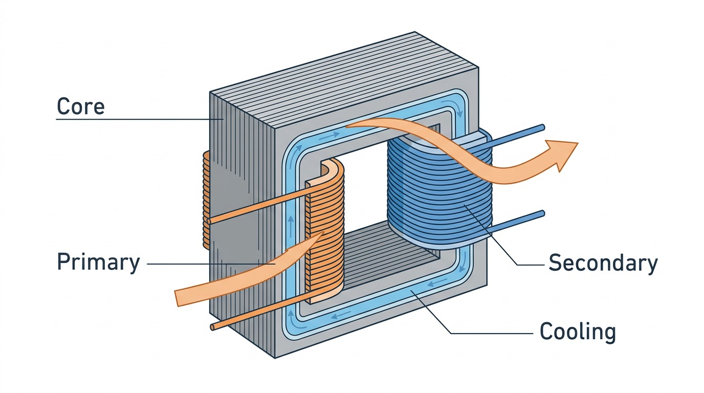
An induction inverter produces an AC waveform at the heating frequency. The coil + workpiece presents an impedance that is rarely convenient for the inverter. A transformer changes the voltage/current ratio so the inverter can operate in a safe region while the coil operates in a practical region for copper size, insulation, and mechanical forces.
In many systems, the transformer also provides isolation and helps package the matching network in a serviceable way.
Why Frequency Changes the Transformer Problem
At higher frequency, core size can shrink for a given volt-second requirement, but winding losses and stray capacitance become more prominent. Skin and proximity effects increase AC resistance. Insulation stress shifts from "RMS thinking" toward "peak voltage and partial discharge thinking," especially in harsh environments.
The engineering implication is that a transformer that looks fine on turns ratio can still fail a duty-cycle test because the loss distribution is wrong.
Loss Budget: Core vs. Winding vs. Stray Losses
Teams often ask "what's the efficiency?" but the more actionable question is "where do the losses go?" High circulating reactive current can make winding losses dominate even when delivered kW is moderate. Stray losses can create local hot spots that drive insulation aging.
For system reliability, require clear data on temperature rise at your operating frequency and duty cycle, not just a generic rating.
Placement: Inside the Cabinet or Near the Coil?
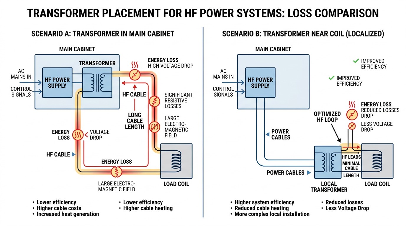
Transformer placement is often driven by layout constraints. If the coil is near the cabinet, integration is straightforward. If the coil is remote, moving the transformer and capacitor bank closer to the coil can reduce the high-current loop length, lowering losses and parasitic resonance risk.
This is the same logic that drives remote heat stations: the resonant loop is a physical object, and shorter is usually better.
A Practical Comparison Table
| Design/Integration Choice | Benefits | Typical Risk | |
|---|---|---|---|
| 1 | Higher coil voltage (ratio up) | Lower coil current, smaller conductors | Higher insulation/arcing risk |
| 2 | Lower coil voltage (ratio down) | Easier insulation margin | Higher I\u00b2R and AC losses |
| 3 | Transformer near coil | Lower HF transmission losses | More distributed equipment |
| 4 | Transformer in main cabinet | Simpler layout/service | HF lead losses if coil is remote |
Leakage Inductance, Capacitance, and the "Hidden" Interaction with the Tank
In induction systems, transformer parasitics matter. Leakage inductance can interact with the capacitor bank and coil inductance, shifting resonant behavior. Stray capacitance can create high-frequency paths that change waveform shape and stress distribution.
The point is not that parasitics are bad; the point is that they must be known and managed. Ask for leakage inductance estimates and ensure the vendor has validated the transformer in a representative tank configuration.
Cooling Is Part of the Electrical Rating
A medium/high-frequency transformer rating without cooling details is incomplete. Water flow, inlet temperature, pressure drop, and water quality assumptions determine whether the transformer will hold temperature in continuous duty. Because winding resistance changes with temperature, transformer heating can also change system behavior during long runs.
In commissioning, treat transformer temperature rise as a stability variable. If electrical measurements drift as the transformer warms, you may be watching the system lose margin.
Choosing Where to Put Voltage Stress
A transformer ratio change is essentially a decision about where you want stress to live. Higher voltage reduces current but increases insulation and clearance requirements. Lower voltage reduces insulation stress but increases current, copper loss, and mechanical forces.
This is why the "best" ratio is application-specific. Close-coupled heat treating may prioritize insulation margin around the part. Long cable runs may prioritize reduced current to reduce loss. The correct answer depends on process geometry and plant constraints.
Mechanical Forces, Vibration, and Long-Term Reliability
Transformers in induction environments do not live in calm electrical rooms. They see vibration from nearby presses, shock from material handling, and thermal cycling from duty cycle variation. These stresses show up as loosened connections, fretting corrosion, and insulation wear.
When specifying a transformer or matching station, include mechanical considerations: bracing, connector strategy, strain relief on water lines, and access for inspection. A transformer that is electrically excellent but mechanically fragile will still become a reliability problem.
Testing That Actually Predicts Field Performance
Nameplate ratings are not enough. Ask for (or perform) tests that reflect your use case: temperature rise at your frequency and duty cycle, cooling pressure-drop verification, dielectric withstand at peak voltage, and a short run that includes realistic reactive circulation. These tests surface hot spots and margin issues early.
EMC and Stray Flux Management
Medium-frequency magnetic fields can induce heating in nearby structural steel if return paths and shielding are not managed. In some installations, magnetic shunts or physical spacing are used to keep stray flux from causing losses or heating in unintended structures. If you see unexplained heating of nearby steelwork, transformer placement and stray flux paths are a likely cause.
Service Access and Downtime: The Forgotten Requirement
Transformers and matching stations are often physically large and heavy. If they are buried behind guards or placed where cranes cannot reach, a simple replacement becomes a multi-shift event. Include service access in layout reviews: clearance, lift points, water shutoff locations, and safe electrical isolation procedures. These details rarely appear in the schematic but dominate real downtime.
Documentation That Keeps Performance Stable After Maintenance
After maintenance events, systems sometimes come back with subtle changes: hose routing, bus bar alignment, or grounding straps. Document the intended physical configuration and include photos in your maintenance package. For induction systems, "as built" physical layout is part of the electrical design.
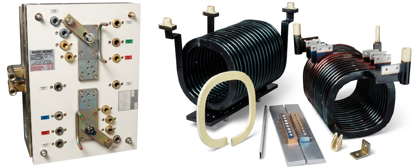
Materials and Construction: Why "HF Transformer" Is Not One Thing
Medium-frequency and high-frequency transformers can use different core materials and winding strategies depending on frequency and power level. Some designs rely on laminated steels in lower MF ranges; others rely on ferrites or specialized materials at higher frequencies. Winding strategies can include foil, transposed conductors, or litz-like bundles to manage AC resistance.
For integrators, the precise materials matter less than what they imply about loss and cooling. The practical question is: can the transformer deliver rated output at your frequency and duty cycle without excessive temperature rise, and does it do so with acceptable size and service access?
Cooling Interfaces and Water Quality Requirements
Design Tip
A recurring field problem is mismatch between equipment assumptions and plant water reality. If a transformer expects low conductivity water and the plant provides untreated water, scaling and corrosion can reduce flow and heat transfer. Specify water quality and inlet temperature range explicitly. If the plant cannot guarantee those, select a cooling architecture (closed loop, heat exchanger, chiller) that can.
Installation Practices That Preserve Performance
Seemingly small installation details can change behavior: long water hoses that trap air, bus bars routed differently after a retrofit, or grounding straps moved during maintenance. Because the physical configuration is part of the electrical design, document it and control changes. This is especially important when the transformer is placed near the process, where exposure to dust and heat can pressure teams to improvise.
Why Some High-Frequency Systems Avoid Magnetic Cores
Radio-frequency transformers used with vacuum tube oscillators may have no magnetic core. Even if your system is solid-state, this detail highlights a broader principle: as frequency rises, the role of core material and magnetics changes, and what is "normal" at 60 Hz is not guaranteed to be optimal at RF.
For modern induction systems, you will still see a wide range of transformer and magnetic products\u2014from line frequency to high frequency\u2014because size limitations, cost factors, power requirements, and frequency range all interact. The practical takeaway is to specify transformers by operating band and duty cycle, not as generic components.
Information That Used to Be "Enough" Is No Longer Enough
Basic information like frequency, kW, kVA, and voltages used to be sufficient for specifying a transformer. In modern systems, that is no longer enough because parasitics, cooling, and EMC behavior can dominate. If you want repeatable results, add requirements for temperature rise tests at operating frequency and for documentation of leakage inductance and cooling interfaces.
Those requirements feel heavy during procurement, but they are lightweight compared to field downtime caused by unexpected heating in a transformer hot spot or by detuning sensitivity introduced through leakage inductance.
Vendor Data to Request (and Why Each Item Matters)
To keep transformer selection grounded, request a short set of data that predicts field performance:
- Temperature rise at your operating frequency and duty cycle, not only at a generic rating
- Cooling pressure-drop and minimum flow so your utilities team can size pumps and hoses correctly
- Leakage inductance and any recommended capacitor placement guidance, because these affect tank tuning and stability
- Insulation test data tied to peak voltage expectations, because peak stress\u2014not only RMS\u2014drives arcing risk and long-term dielectric aging
If a supplier cannot provide these items, you can still proceed, but you should treat the project as higher risk and plan additional acceptance testing before production.
Practical Field Check: What to Look for After the First Month
After a transformer has run in production for a few weeks, inspect for early indicators of stress: discoloration at connection points, loosened mechanical bracing, and any evidence of localized overheating near windings or cooling interfaces. Compare recorded electrical signatures (current, voltage, detuning indicators) to commissioning baselines. If the operating point has drifted, investigate cooling performance and connection integrity before changing recipes. Early drift is often a maintenance and installation issue, not a process issue.
FAQ about Medium- and High-Frequency Transformers in Induction Systems
Q: Why can a transformer run hot even at modest delivered kW?
Because RMS current can be high when reactive power circulation is high. Copper loss scales with RMS current even if real power is moderate.
Q: What data should you require in a specification?
Loss/temperature rise at operating frequency, cooling requirements (flow/inlet temperature), leakage inductance estimate, insulation test data, and expected overload capability.
Q: What is the most common integration mistake?
Ignoring the impact of distance to the coil. Long high-frequency connections can dominate loss and detuning sensitivity; moving transformer/matching hardware closer to the load often solves the root cause.
Conclusion: Transformer Ratio Is Not a Minor Detail
A well-chosen transformer does more than match impedance. It shifts stress between voltage and current domains, changing what fails first and how stable the control loop feels during process variation. Specify it with the same discipline you apply to the inverter.
Keep Learning
Simultaneous Dual-Frequency Induction Heating: When One Frequency Forces the Wrong Compromise
Key Takeaways One frequency, one compromise: When geometry demands both deep bulk heating and controlled surface gradients simultaneously, a single frequency forces an unacceptable trade-off—dual-frequency widens the process window. Give each channel a role: Assign the lower frequency to bulk penetration and the higher frequency to surface shaping. Structured recipe development follows naturally from this separation. Validate with metrics, not opinions: Dual-frequency is justified only when controlled......
Power Supplies by Application Family: Joining, Mass Heating, and Strip Processing
Key Takeaways Joining operations (brazing, soldering, bonding) demand higher frequencies and matching flexibility to handle variable coil coupling and precision surface heating. Mass heating lines (billets, bars, slabs) prioritize continuous duty, efficiency, and ruggedness at high power levels with multi-coil zone control. Strip processing requires architectures that separate control electronics from high-frequency inverter modules to cope with harsh installation environments. Specifying only kW and ......
Simultaneous Dual-Frequency Induction Power: When One Frequency Forces the Wrong Compromise
Key Takeaways Dual-frequency is justified by robustness, not complexity: It should only be adopted when a single frequency forces an unacceptable compromise between surface and bulk heating requirements. Give each frequency a defined role: Assign the lower frequency to bulk heating/penetration and the higher frequency to surface shaping—then develop recipes one variable at a time. The combining network is the engineering center of gravity: Frequency-selective coupling paths, thermal rating for worst-c......
Applying Induction Power Supplies in the Real World: Constraints That Decide Uptime and Quality
Key Takeaways Application constraints dominate real-world performance: Two induction systems with identical kW ratings can behave very differently depending on cable length, cooling water temperature, dust levels, and fixture repeatability. Design for drift, not for perfect day one: Coils deform, filters clog, sensors drift, and connectors loosen under thermal cycling. Baseline monitoring during commissioning is essential. Mechanical repeatability often beats control complexity: Improving fixturing an......
Medium- and High-Frequency Transformers in Induction Systems: Design Drivers Engineers Should Actually Care About
Key Takeaways Not Passive: Transformers set the electrical operating point for the entire induction station—coil voltage, current, capacitor stress, and inverter margin all depend on transformer choice. Frequency Effects: At higher frequencies, winding losses and stray capacitance dominate; a transformer that looks fine on turns ratio can fail a duty-cycle test if loss distribution is wrong. Placement Matters: Moving the transformer and capacitor bank closer to the coil reduces high-frequency loop len......
Load Matching in Induction Heating: Designing for Stability, Efficiency, and Real-World Variation
Key Takeaways Dynamic Load: Induction heating loads are not fixed—coupling, material properties, and temperature all shift impedance during operation, making matching a continuous design challenge. Q Factor Matters: High-Q loads can produce large circulating currents and capacitor stress even at modest delivered kW; design for the worst-case kVA, not just power. Discrete Ranges Win: Transformer taps and capacitor steps that cover discrete matching ranges outperform a single broad-range configuration f......