
From Flat Steel to Pressure Vessel — The Unforgiving Science of Building a Heat Exchanger
8 min
- From Flat Steel to Pressure Vessel — The Unforgiving Science of Building a Heat Exchanger
- The Drawing Is a Legal and Scientific Contract
- Steel Has a Memory: The Science of Rolling
- The Most Critical Joint in the Machine
- When Welding Gives Way to Brazing
- The Final Exam: Hydrostatic Testing
- More Than Metalworking
- FAQ
From Flat Steel to Pressure Vessel — The Unforgiving Science of Building a Heat Exchanger
Walk through any large petrochemical plant or power station, and you will almost certainly pass a row of hulking steel cylinders, each the size of a school bus, wrapped in insulation and laced with pipes. They are easy to ignore. They do not move. They do not spark or roar. And yet, without them, the entire plant stops. These are shell-and-tube heat exchangers — and building one is far more demanding than it looks.
A heat exchanger is, at its core, a device for moving thermal energy from one fluid to another without letting those fluids mix. Hot process gas flows through a bundle of thin tubes; cooler water flows around them. Heat migrates through the metal walls. Simple enough in concept — but the engineering reality is a minefield of metallurgy, physics, and precision geometry. Based on the rigorous standards of the Heat Exchanger Design Handbook, what follows is the story of how these machines are actually made.
The Drawing Is a Legal and Scientific Contract
Before a single piece of steel is cut, someone spends weeks producing a fabrication drawing. In most industries, a drawing is a guide. In heat exchanger fabrication, it is binding. Industry codes such as TEMA (Tubular Exchanger Manufacturers Association) and the ASME Pressure Vessel Code treat this document as the genetic blueprint of the vessel — a legal contract between the designer, the fabricator, and, ultimately, the laws of physics.
The drawing must specify the "corrosion allowance" — an extra thickness of metal deliberately added because engineers know, with certainty, that the interior will corrode over the years. It defines the Maximum Allowable Working Pressure (MAWP) and the Minimum Design Metal Temperature (MDMT), the cold extreme at which steel becomes dangerously brittle. It also mandates a Non-Destructive Testing plan, specifying exactly which welds must be X-rayed or ultrasonically scanned for hidden flaws. Every number on that drawing is load-bearing.
Steel Has a Memory: The Science of Rolling
The cylindrical shell of a heat exchanger begins its life as a flat steel plate, often several centimeters thick. A machine called a plate roll grips it and progressively bends it into a cylinder — a process engineers call cold-forming. It sounds straightforward. It is not.
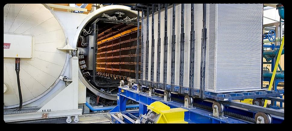
When you bend steel without heating it, you are forcing its internal crystal structure to deform permanently. The outer fibers of the plate are stretched in tension; the inner fibers are compressed. Industry codes impose a strict limit on this: fiber strain must stay between 3% and 4.5%. Exceed that threshold and the metal accumulates so much internal stress that its properties change — it becomes harder but more prone to cracking. The remedy is a post-forming heat treatment, essentially slow-cooking the steel in a furnace to let its atomic structure relax back to a stable state. Skip this step, and you are building a time bomb.
Once rolled, the seam of the cylinder must be welded shut. Here, fabricators encounter a subtle but serious trap. To hold the rolled plate in shape while the main weld is prepared, they use small "tack welds" — temporary dabs of weld metal. The temptation is to make these small and quick. The science says otherwise. A tiny spot of molten metal deposited on a cold, massive steel plate cools in seconds. That rapid quench freezes the steel's crystalline structure into a phase called martensite — a hard, glass-like form of steel that shatters rather than bends. Even a temporary weld left in this condition becomes a crack initiation site. Engineering rigor demands that tack welds be substantial enough to cool slowly, preserving the metal's toughness.
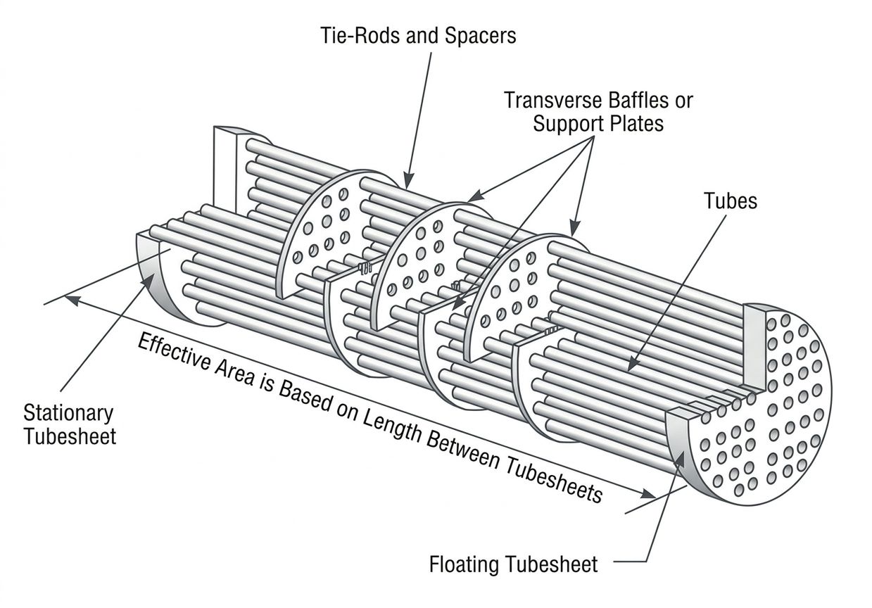
The Most Critical Joint in the Machine
Inside the shell, hundreds or even thousands of tubes are held in place at each end by a thick plate called a tubesheet. The joint where tube meets tubesheet is the single most failure-prone location in the entire device. Fluids under high pressure are separated by nothing more than this connection — and it cannot leak.
The standard method for making this joint is called rolling-in. A mandrel fitted with hardened rollers is inserted into the tube end and rotated under force. The tube wall expands outward, past its yield point — meaning it deforms permanently — until it presses hard against the tubesheet hole. The result is an interference fit, conceptually similar to a shrink-fitted shaft in a bearing: the metal is prestressed into a seal that can hold hundreds of pounds per square inch.
The challenge is calibration. Under-roll the joint, and microscopic gaps remain — invisible to the eye, but enough for process fluid to seep through under pressure. Over-roll it, and the tubesheet itself can warp from accumulated stress, while the tube wall becomes work-hardened and brittle. Finding the correct torque setting is not a matter of experience and intuition. It requires a physical mock-up: a test assembly built from the exact same materials and to the exact same dimensions as the real unit. Engineers roll several test joints, measure them, and adjust until the parameters are proven. Only then does work begin on the actual exchanger.
When Welding Gives Way to Brazing
For certain applications — cryogenic gas separation, for instance, where temperatures plunge below −150°C — aluminum exchangers are used instead of steel. Aluminum cannot be joined by conventional welding in these configurations, so fabricators turn to brazing: a process where a filler metal with a lower melting point is flowed into the joint by capillary action, bonding the surfaces without melting them.
The science here shifts from mechanics to surface chemistry. Brazing depends entirely on "wetting" — the ability of the molten filler to spread across the base metal like water on clean glass. The enemies of wetting are oxides and organic contamination. Aluminum forms an oxide layer within minutes of exposure to air; oils from human skin are equally destructive to the bond. As a result, once parts have been chemically cleaned, they are handled exclusively with gloves and stored in controlled environments. A single fingerprint on a pre-cleaned surface can compromise the joint. It is, in every practical sense, surgery performed at industrial scale.
The Final Exam: Hydrostatic Testing
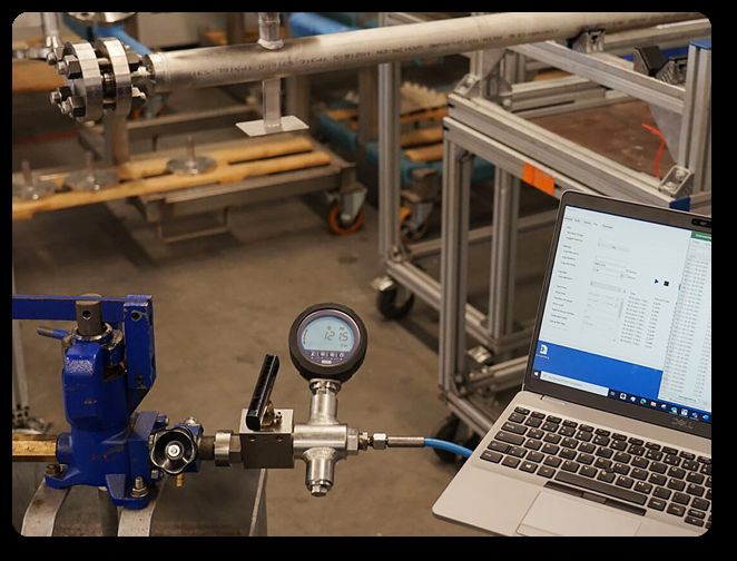
Once the exchanger is fully assembled, it faces its final examination. The vessel is filled with water and pressurized to a level above its rated working pressure — typically 1.3 to 1.5 times the MAWP. The choice of water is deliberate: unlike a gas, water does not compress. If the vessel fails under hydraulic pressure, it simply splits and leaks. If it were filled with compressed gas and failed, the sudden release of stored energy would be explosive.
The vessel is held at test pressure for a specified period while inspectors examine every weld, flange face, and tube joint for seepage. Any weeping of water, any drop in pressure, means a return to the workshop. There is no partial pass. The exchanger either holds, or it does not.
More Than Metalworking
It is tempting to think of fabrication as a purely practical trade — cut, bend, weld, test. But building a heat exchanger is the practical application of materials science at every step. The fabricator who understands why martensite forms in a rapidly cooled tack weld, or why a fingerprint ruins a brazed joint, is not just following a procedure manual. They are applying physics.
That is what makes the stakes so high — and the craft so demanding. These steel cylinders will operate for decades, holding back corrosive fluids at pressures that would reduce a lesser vessel to shrapnel. Every microscopic decision made on the shop floor will either hold or yield under those conditions. In this field, quality is not a standard to aim for. It is the only thing standing between a running plant and a catastrophe.

FAQ
Q: Why can't you just weld a heat exchanger together quickly like other steel structures?
Heat exchangers operate under extreme pressure and temperature conditions where even microscopic flaws can lead to catastrophic failure. Rapid welding creates martensite — a brittle form of steel that cracks easily. Every weld must cool slowly enough to maintain the metal's toughness, and critical joints must be X-rayed or ultrasonically tested for hidden defects. The stakes are too high for shortcuts.
Q: What makes the tube-to-tubesheet joint so difficult to get right?
This joint is where high-pressure fluids are separated by nothing but the connection itself. The tubes are "rolled in" — expanded past their yield point to create an interference fit. Roll too little and fluid leaks through microscopic gaps; roll too much and you warp the tubesheet or make the tube brittle. Getting it right requires building test assemblies from the exact materials and measuring results before touching the real exchanger.
Q: Why do aluminum heat exchangers require such extreme cleanliness during fabrication?
Aluminum exchangers are brazed rather than welded, which relies on molten filler metal wetting the surface through capillary action. Aluminum oxidizes within minutes of air exposure, and even a fingerprint leaves oils that prevent proper bonding. Once cleaned, parts must be handled only with gloves in controlled environments — essentially performing surgery at industrial scale.
Keep Learning
Simultaneous Dual-Frequency Induction Heating: When One Frequency Forces the Wrong Compromise
Key Takeaways One frequency, one compromise: When geometry demands both deep bulk heating and controlled surface gradients simultaneously, a single frequency forces an unacceptable trade-off—dual-frequency widens the process window. Give each channel a role: Assign the lower frequency to bulk penetration and the higher frequency to surface shaping. Structured recipe development follows naturally from this separation. Validate with metrics, not opinions: Dual-frequency is justified only when controlled......
Power Supplies by Application Family: Joining, Mass Heating, and Strip Processing
Key Takeaways Joining operations (brazing, soldering, bonding) demand higher frequencies and matching flexibility to handle variable coil coupling and precision surface heating. Mass heating lines (billets, bars, slabs) prioritize continuous duty, efficiency, and ruggedness at high power levels with multi-coil zone control. Strip processing requires architectures that separate control electronics from high-frequency inverter modules to cope with harsh installation environments. Specifying only kW and ......
Simultaneous Dual-Frequency Induction Power: When One Frequency Forces the Wrong Compromise
Key Takeaways Dual-frequency is justified by robustness, not complexity: It should only be adopted when a single frequency forces an unacceptable compromise between surface and bulk heating requirements. Give each frequency a defined role: Assign the lower frequency to bulk heating/penetration and the higher frequency to surface shaping—then develop recipes one variable at a time. The combining network is the engineering center of gravity: Frequency-selective coupling paths, thermal rating for worst-c......
Applying Induction Power Supplies in the Real World: Constraints That Decide Uptime and Quality
Key Takeaways Application constraints dominate real-world performance: Two induction systems with identical kW ratings can behave very differently depending on cable length, cooling water temperature, dust levels, and fixture repeatability. Design for drift, not for perfect day one: Coils deform, filters clog, sensors drift, and connectors loosen under thermal cycling. Baseline monitoring during commissioning is essential. Mechanical repeatability often beats control complexity: Improving fixturing an......
Medium- and High-Frequency Transformers in Induction Systems: Design Drivers Engineers Should Actually Care About
Key Takeaways Not Passive: Transformers set the electrical operating point for the entire induction station—coil voltage, current, capacitor stress, and inverter margin all depend on transformer choice. Frequency Effects: At higher frequencies, winding losses and stray capacitance dominate; a transformer that looks fine on turns ratio can fail a duty-cycle test if loss distribution is wrong. Placement Matters: Moving the transformer and capacitor bank closer to the coil reduces high-frequency loop len......
Load Matching in Induction Heating: Designing for Stability, Efficiency, and Real-World Variation
Key Takeaways Dynamic Load: Induction heating loads are not fixed—coupling, material properties, and temperature all shift impedance during operation, making matching a continuous design challenge. Q Factor Matters: High-Q loads can produce large circulating currents and capacitor stress even at modest delivered kW; design for the worst-case kVA, not just power. Discrete Ranges Win: Transformer taps and capacitor steps that cover discrete matching ranges outperform a single broad-range configuration f......