
Electromagnetic Roots: The Evolution of Industrial Induction Heating
8 min
- 1831: The Dawn of Electromagnetic Induction
- Formalizing the Invisible: Faraday and Lenz
- The Transformer Era: When Heat Was a Nuisance
- The Radical Pivot: From Waste to Industrial Process
- 1922: The Industrial Unlock
- The Path Toward Precision
- FAQ
Electromagnetic Roots: The Evolution of Industrial Induction Heating
The modern industrial landscape is defined by its ability to manipulate materials with extreme precision and efficiency. Among the most transformative technologies in this regard is induction heating—a process that uses invisible magnetic fields to generate heat directly within a conductive material. While it is now a cornerstone of foundries, automotive manufacturing, and aerospace engineering, its journey from a laboratory curiosity to an industrial powerhouse spans nearly two centuries of scientific discovery and engineering ingenuity.
Induction heating is fundamentally different from traditional thermal processes. In a conventional furnace, heat is transferred to a workpiece through radiation, convection, or conduction from an external source. In contrast, induction heating generates heat internally. This internal generation allows for heating rates and localized control that are physically impossible with torches or ovens. To appreciate how we reached this level of sophistication, we must return to the nineteenth century, to a small laboratory in London where the foundations of electromagnetism were first laid.
1831: The Dawn of Electromagnetic Induction
The story of induction heating begins in 1831 with the English physicist Michael Faraday. At the time, the relationship between electricity and magnetism was a frontier of human knowledge. Faraday suspected that if an electric current could produce a magnetic field, then a magnetic field should be able to produce an electric current.
His experimental setup was elegant in its simplicity. He took an iron ring and wrapped two separate coils of copper wire around it. The first coil, the primary, was connected to a battery via a switch. The second coil, the secondary, was connected to a galvanometer—a sensitive instrument used to detect electric current. Crucially, there was no physical electrical connection between the primary and secondary coils; they were isolated from each other by the insulation on the wires.
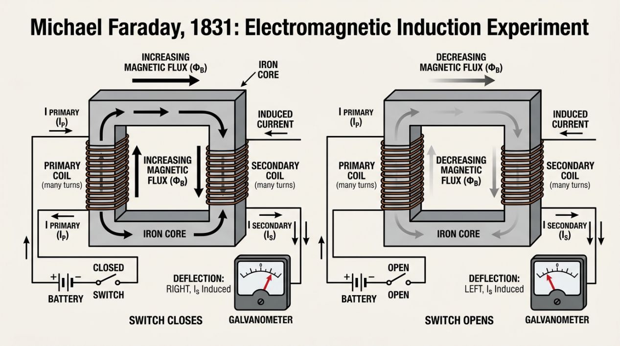
Faraday observed a startling phenomenon. When he closed the switch to the primary coil, the galvanometer needle flickered, indicating a brief pulse of electricity in the secondary coil. When he kept the switch closed and the current in the primary remained steady, the galvanometer returned to zero. However, the moment he opened the switch, the needle flickered again, but in the opposite direction.
Faraday correctly deduced that a changing magnetic field was the key. A steady magnetic field produced no current, but the transition—the growth or collapse of the magnetic flux—induced a voltage in the secondary circuit. This discovery, known as Faraday’s Law of Induction, remains the fundamental principle behind every transformer, electric motor, and induction heater in use today.
Formalizing the Invisible: Faraday and Lenz
Faraday’s Law states that the electro-motive force (emf) or voltage induced in a circuit is directly proportional to the time rate of change of the magnetic flux through that circuit. Mathematically, this meant that the faster you could change the magnetic field, the more voltage you could induce.
Shortly after Faraday's discovery, the German physicist Heinrich Lenz added a critical refinement known as Lenz’s Law. This law defines the direction of the induced current. Lenz determined that the polarity of the induced voltage is always such that it produces a current whose own magnetic field opposes the change in the original magnetic flux. In essence, induction is a manifestation of physical inertia; the system resists changes in its magnetic state. If you try to increase the magnetic field, the induced current creates a field to push back. If you try to decrease it, the induced current tries to sustain it.
The Transformer Era: When Heat Was a Nuisance
For much of the nineteenth century, engineers were not trying to heat metal with induction; they were trying to transfer power. These pioneers were focused on developing transformers to step voltages up or down for efficient electrical transmission. In these early systems, induction was the mechanism of energy transfer, but it came with a frustrating "side effect": the iron cores of the transformers became hot.
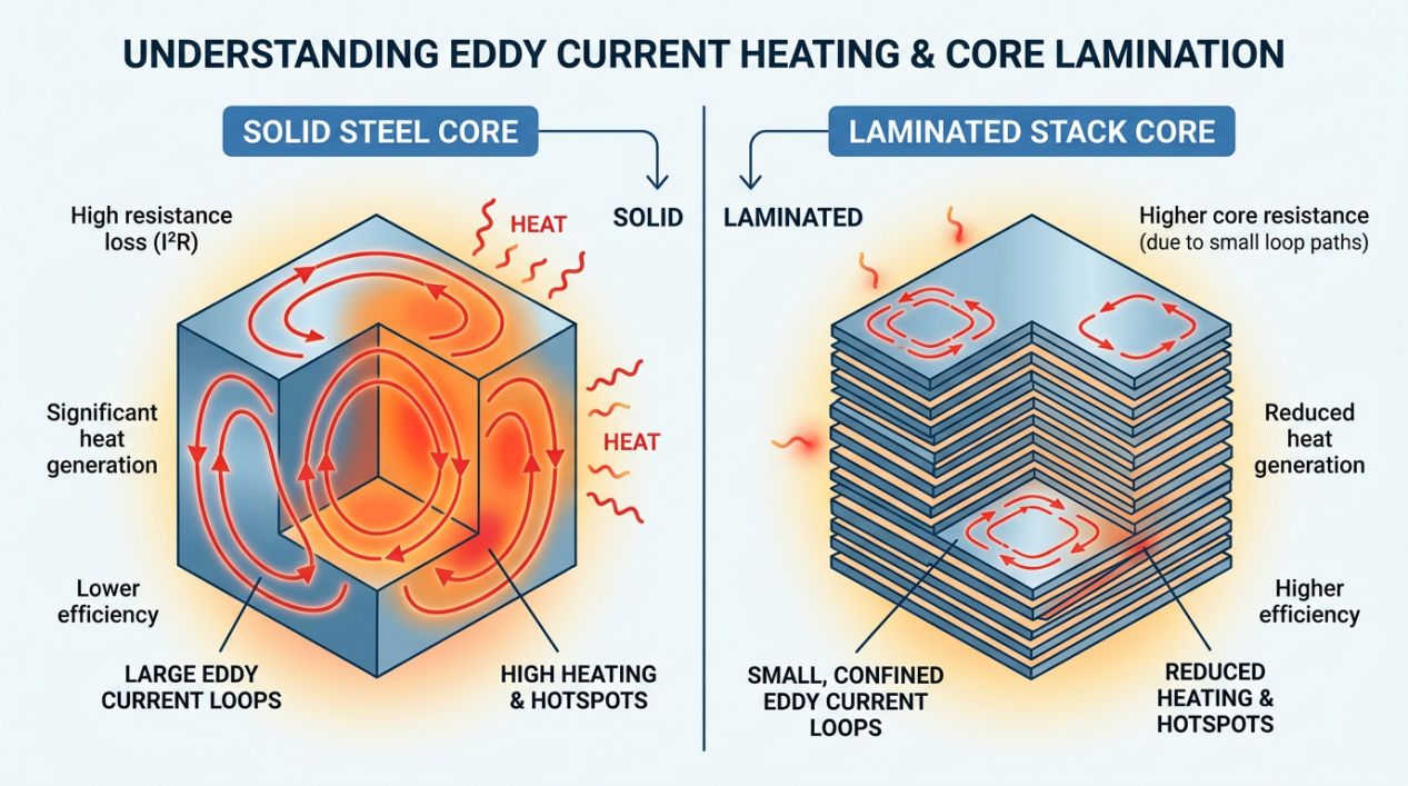
This phenomenon was initially viewed purely as a waste of energy, referred to as "core loss." The heat was caused by eddy currents—swirling loops of electrical current induced within the solid volume of the conductive iron core. Because iron has electrical resistance, these currents generated heat through the standard Joule heating effect.
To combat this unwanted heating, engineers developed the technique of lamination. Instead of using a solid block of iron for the transformer core, they began using stacks of thin steel sheets, each separated by a layer of insulation. This physical barrier broke the path for large eddy current loops, confining the currents to the thickness of each individual sheet. This significantly reduced the total heat generated, making the transformers much more efficient and reliable.
The Radical Pivot: From Waste to Industrial Process
In the late 1800s, a profound shift in thinking occurred. Engineers began to ask: what if we didn't try to stop the heating? What if we leveraged the very effect we were trying to suppress in transformers to deliberately melt and process metals? This was the "pivot" that transformed a nuisance into a revolution. Instead of laminating metal to prevent heat, they would expose solid conductive loads to intense, high-frequency magnetic fields to maximize internal heat generation.
In the early 1900s, Edwin Northrup became a pivotal figure in realizing this vision. He developed specialized equipment to heat metals using a cylindrical crucible surrounded by an induction coil. However, these early systems faced a significant technical bottleneck: the power source. Northrup utilized spark-gap power generators, which were the state of the art at the time. While these were capable of proving the concept in a laboratory setting or for melting very small quantities of precious metals, they could not produce the massive amounts of power required for heavy industrial foundries.
1922: The Industrial Unlock
The true commercial viability of induction heating arrived in 1922 with the development of high-power motor generators. Unlike the fragile and limited spark-gap systems, motor generators provided a robust, reliable source of alternating current at the frequencies and power levels needed for large-scale operations.
- Precision Temperature Control: Because the heat is generated internally, the power can be adjusted instantly to maintain exact metallurgical requirements.
- Cleanliness: Induction heating is inherently "clean," as there are no combustion by-products to contaminate the melt.
- Homogeneity: The electromagnetic forces within the melt create a natural "stirring" effect, ensuring uniform alloy distribution and temperature throughout the crucible.
The Path Toward Precision
By the late 1920s and 1930s, the focus of induction technology began to expand from bulk melting to selective heating. Engineers at companies like Midvale Steel (1927) and the Ohio Crankshaft Company (mid-1930s) realized that by manipulating the frequency of the magnetic field, they could control how deep the heat penetrated the metal.
They discovered that high frequencies tend to concentrate current on the surface of a part—a phenomenon known as the "skin effect." This allowed for the surface hardening of critical components like crankshafts. By heating and quenching just the exterior, they could create a part with a hard, wear-resistant "skin" and a tough, flexible core. This ability to "sculpt" heat with surgical precision marked the transition of induction from a raw power tool to a refined metallurgical instrument.
The journey from Faraday's iron ring to the high-precision hardening of automotive components illustrates a classic engineering narrative: the transformation of a scientific curiosity and a parasitic waste effect into a foundational industrial technology. By mastering the invisible interplay of magnetic flux and eddy currents, engineers unlocked a level of control over matter that continues to drive innovation in high-performance materials today.
FAQ
Q: What is induction heating and how is it different from traditional heating?
Induction heating generates heat directly inside a conductive material using magnetic fields, rather than transferring heat from an external source. This allows for faster heating rates, precise temperature control, and localized heating that conventional furnaces or torches cannot achieve.
Q:Why was heat initially considered a problem in early electromagnetic systems?
In 19th-century transformers, the heat generated by eddy currents in iron cores was seen as unwanted energy loss. Engineers developed laminated cores—thin insulated steel sheets—to reduce this "waste heat." The breakthrough came when engineers realized they could intentionally maximize this effect to melt and process metals.
Q: How does frequency affect induction heating applications?
The frequency of the magnetic field controls heat penetration depth through the "skin effect." High frequencies concentrate heat at the surface, enabling processes like surface hardening of crankshafts—creating a hard exterior with a tough core. Lower frequencies allow deeper heat penetration for applications like bulk melting in foundries.
Keep Learning
Simultaneous Dual-Frequency Induction Heating: When One Frequency Forces the Wrong Compromise
Key Takeaways One frequency, one compromise: When geometry demands both deep bulk heating and controlled surface gradients simultaneously, a single frequency forces an unacceptable trade-off—dual-frequency widens the process window. Give each channel a role: Assign the lower frequency to bulk penetration and the higher frequency to surface shaping. Structured recipe development follows naturally from this separation. Validate with metrics, not opinions: Dual-frequency is justified only when controlled......
Power Supplies by Application Family: Joining, Mass Heating, and Strip Processing
Key Takeaways Joining operations (brazing, soldering, bonding) demand higher frequencies and matching flexibility to handle variable coil coupling and precision surface heating. Mass heating lines (billets, bars, slabs) prioritize continuous duty, efficiency, and ruggedness at high power levels with multi-coil zone control. Strip processing requires architectures that separate control electronics from high-frequency inverter modules to cope with harsh installation environments. Specifying only kW and ......
Simultaneous Dual-Frequency Induction Power: When One Frequency Forces the Wrong Compromise
Key Takeaways Dual-frequency is justified by robustness, not complexity: It should only be adopted when a single frequency forces an unacceptable compromise between surface and bulk heating requirements. Give each frequency a defined role: Assign the lower frequency to bulk heating/penetration and the higher frequency to surface shaping—then develop recipes one variable at a time. The combining network is the engineering center of gravity: Frequency-selective coupling paths, thermal rating for worst-c......
Applying Induction Power Supplies in the Real World: Constraints That Decide Uptime and Quality
Key Takeaways Application constraints dominate real-world performance: Two induction systems with identical kW ratings can behave very differently depending on cable length, cooling water temperature, dust levels, and fixture repeatability. Design for drift, not for perfect day one: Coils deform, filters clog, sensors drift, and connectors loosen under thermal cycling. Baseline monitoring during commissioning is essential. Mechanical repeatability often beats control complexity: Improving fixturing an......
Medium- and High-Frequency Transformers in Induction Systems: Design Drivers Engineers Should Actually Care About
Key Takeaways Not Passive: Transformers set the electrical operating point for the entire induction station—coil voltage, current, capacitor stress, and inverter margin all depend on transformer choice. Frequency Effects: At higher frequencies, winding losses and stray capacitance dominate; a transformer that looks fine on turns ratio can fail a duty-cycle test if loss distribution is wrong. Placement Matters: Moving the transformer and capacitor bank closer to the coil reduces high-frequency loop len......
Load Matching in Induction Heating: Designing for Stability, Efficiency, and Real-World Variation
Key Takeaways Dynamic Load: Induction heating loads are not fixed—coupling, material properties, and temperature all shift impedance during operation, making matching a continuous design challenge. Q Factor Matters: High-Q loads can produce large circulating currents and capacitor stress even at modest delivered kW; design for the worst-case kVA, not just power. Discrete Ranges Win: Transformer taps and capacitor steps that cover discrete matching ranges outperform a single broad-range configuration f......