
Dimensional Stability in PCB Manufacturing: Precision Solutions for Reliable PCBs
7 min
- What is Dimensional Stability and Why Does It Matter?
- Key Factors That Affect Dimensional Stability
- Common Problems Caused by Poor Dimensional Stability
- How Professional Manufacturers Deliver Superior Dimensional Stability
- Practical Tips to Achieve Better Dimensional Stability
- Frequently Asked Questions about Dimensional Stability
- Conclusion: Choose Precision Manufacturing for Reliable PCBs
Key Takeaways
Dimensional stability is a PCB’s ability to maintain precise dimensions and flatness under thermal, humidity, and mechanical stresses. It is essential for accurate layer registration, preventing warpage, via cracks, and assembly failures in multilayer boards. Achieving this requires high-Tg FR-4 materials with low CTE, symmetric stack-ups, balanced copper, and tightly controlled lamination. Professional manufacturing delivers <0.75% bow/twist and ±0.1 mm tolerances, ensuring higher yields and superior reliability in automotive, medical, and telecom applications.
Dimensional stability is the ability of a PCB substrate and finished board to maintain its intended dimensions under varying temperatures, humidity, mechanical stress, and chemical exposure during fabrication, assembly, and operation. For engineers designing high-reliability electronics, this property directly determines registration accuracy in multilayer boards, solder joint integrity, and long-term field performance. Poor dimensional stability can cause trace misalignment, via cracking, or board warpage—issues that lead to assembly failures and reduced product lifespan.
In practice, dimensional stability becomes critical as boards shrink, layer counts increase, and operating environments demand tighter tolerances. Industry data shows that even minor shifts of 0.1–0.2 mm can exceed acceptable limits for fine-pitch components or high-density interconnects. Professional PCB manufacturers address this through careful material selection, controlled processes, and rigorous quality systems to deliver boards that meet or exceed IPC standards for bow and twist (typically <0.75% for most applications).
What is Dimensional Stability and Why Does It Matter?
Dimensional stability quantifies a material’s resistance to change in length, width, or thickness due to environmental or processing stresses. In PCB terms, it is measured by changes in feature positions (e.g., hole-to-hole or pad-to-pad registration) and overall board flatness. Key metrics include coefficient of thermal expansion (CTE) in X/Y and Z axes, glass transition temperature (Tg), and moisture absorption.
The impact is immediate and measurable. During lamination, resin shrinkage and copper expansion can shift inner layers by tens of microns if not compensated. In reflow soldering, CTE mismatch between FR-4 (typically 13–18 ppm/°C in X/Y) and copper (17 ppm/°C) or components creates stress that warps boards or fractures vias. Real-world consequences include misaligned BGA balls, open circuits, or intermittent failures in automotive, medical, and telecom applications where boards endure thermal cycling from -40°C to +125°C.
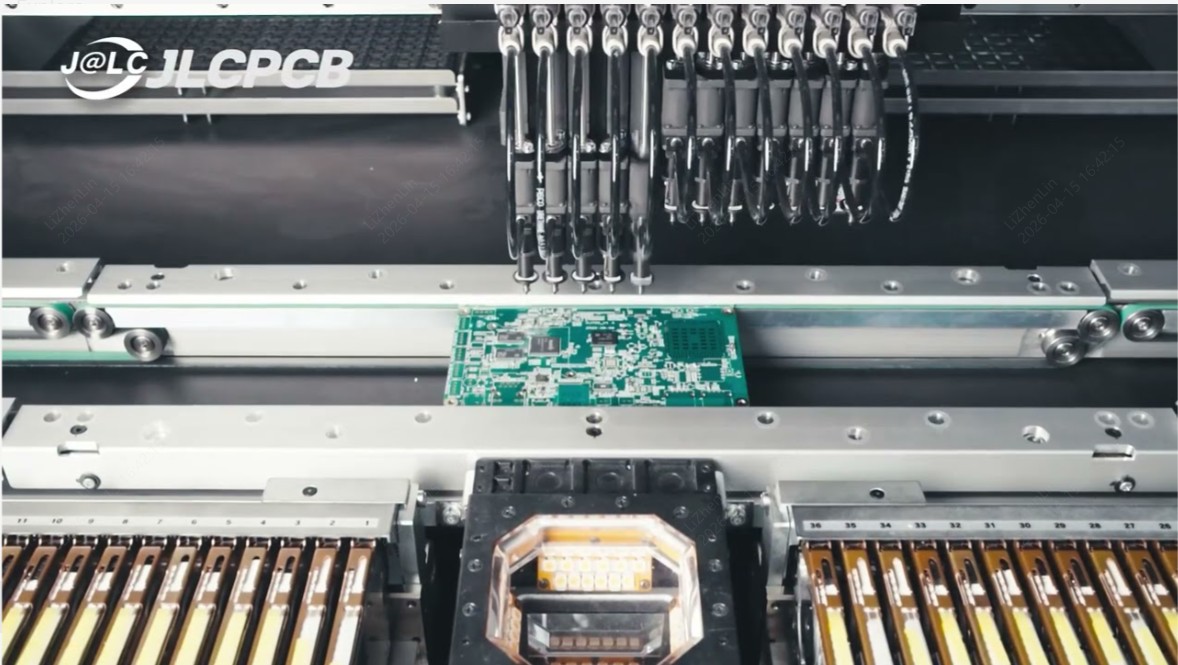
Engineers prioritize dimensional stability because it directly correlates with yield and reliability. Boards with stable dimensions simplify automated optical inspection (AOI) and pick-and-place processes, reducing scrap and field returns.
Key Factors That Affect Dimensional Stability
Material Selection and Its Critical Role
Material choice forms the foundation of dimensional stability. Standard FR-4 laminates, reinforced with woven E-glass and epoxy resin, offer a balanced CTE and good mechanical strength. Higher-Tg variants (150–160°C or 170°C+) reduce Z-axis expansion above the glass transition point, minimizing via stress during lead-free soldering.
The table below summarizes typical CTE values for common PCB materials (X/Y plane):
| Material | CTE (ppm/°C, X/Y) | Tg (°C) | Typical Use Case |
|---|---|---|---|
| Standard FR-4 | 13–18 | 130–140 | General-purpose, cost-sensitive |
| High-Tg FR-4 | 12–15 | 150–170+ | Multilayer, high-reliability |
| Rogers/PTFE | 10–16 | >280 | RF/microwave |
| Polyimide | 12–15 | 250–260 | Flexible, extreme environments |
Professional manufacturers source Grade A FR-4 from reputable suppliers to ensure consistent resin content and low moisture absorption, further enhancing stability.
Manufacturing Processes That Control Stability
Lamination is the most influential step. Multiple cores and prepregs are stacked under heat and pressure; any imbalance in resin flow or copper distribution causes differential shrinkage. Precise scaling factors (compensation for material movement) and controlled press cycles maintain layer-to-layer registration within tight limits.
Subsequent processes—drilling, imaging, etching, and plating—must preserve these dimensions. Over-etching or uneven plating can introduce internal stresses. Leading facilities use automated controls and vacuum-assisted presses to minimize variability.
Design and Environmental Challenges
Balanced copper distribution across layers, symmetric stack-ups , and adequate clearances reduce bow and twist. Environmental factors such as humidity during storage or rapid temperature ramps in assembly further test stability. Designers mitigate these by following IPC-2221 guidelines and specifying panelization for small boards to improve handling rigidity.
Common Problems Caused by Poor Dimensional Stability
Assembly Failures and Reliability Risks
- Warpage exceeding 0.75% can prevent proper solder paste contact or cause component tombstoning.
- In fine-pitch BGAs, even 50 μm of shift leads to opens or shorts.
- Thermal cycling exacerbates micro-cracks in vias or solder joints due to CTE mismatch, shortening mean time between failures (MTBF).
Industry-Specific Requirements and Consequences
Aerospace and automotive standards demand <0.5% bow/twist and tighter hole-position tolerances. Medical devices require traceability and zero-defect levels. Failure to meet these results in costly redesigns, delayed certifications, or field failures that damage brand reputation.
How Professional Manufacturers Deliver Superior Dimensional Stability
Advanced Materials and Innovative Techniques
Expert manufacturers select high-Tg FR-4 laminates and apply scaling algorithms based on empirical shrinkage data for each material batch. Controlled resin content and low-moisture prepregs further limit movement. These steps ensure registration accuracy even in 8–12 layer boards.
State-of-the-Art Facilities and Process Controls
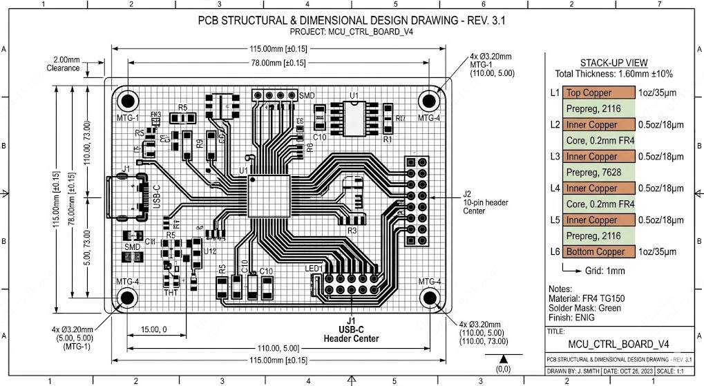
Modern facilities employ computer-controlled hydraulic or vacuum presses with precise temperature ramping and cooling profiles. Automated material handling prevents contamination or uneven pressure. Dimension tolerances are held to ±0.1 mm for outlines, while thickness stays within ±10% (for boards ≥1.0 mm) or ±0.1 mm (thinner boards). Such controls directly translate to predictable dimensional behavior.
Rigorous Quality Assurance and Proven Results
AOI, X-ray, and electrical testing verify every board against design data. Statistical process control tracks key parameters like hole position and flatness. Manufacturers achieving these standards consistently deliver boards with <0.5% warpage and reliable performance across thermal cycles.
Practical Tips to Achieve Better Dimensional Stability
- Use symmetric stack-ups and balanced copper pours.
- Specify high-Tg material for boards >4 layers or high-temperature assembly.
- Add fiducials and panel rails for better registration.
- Follow manufacturer design rules for minimum clearances and aspect ratios.
- Request impedance control where signal integrity matters.
Frequently Asked Questions about Dimensional Stability
Q: What is dimensional stability in PCB manufacturing?
Dimensional stability is a PCB’s ability to maintain its exact designed dimensions under heat, humidity, and mechanical stress. It ensures accurate layer registration, flatness, and reliable assembly.
Q: How does material choice affect dimensional stability?
Higher-Tg FR-4 materials (150–170°C+) and lower CTE values reduce expansion and shrinkage. This minimizes warpage and via stress during soldering and thermal cycling.
Q: What problems result from poor dimensional stability?
Common issues include board warpage >0.75%, misaligned pads, tombstoning, via cracks, and higher field failure rates in automotive, medical, and telecom applications.
Q: How can engineers ensure better dimensional stability?
Use symmetric stack-ups, specify high-Tg materials when needed, follow DFM guidelines, and partner with manufacturers offering tight tolerances (±0.1 mm) and full quality reports.
Conclusion: Choose Precision Manufacturing for Reliable PCBs
Dimensional stability is not an afterthought; it is a foundational requirement for modern electronics. By understanding its drivers, avoiding common pitfalls, and working with manufacturers that combine advanced materials, controlled processes, and rigorous quality systems, engineers achieve the precision needed for today’s demanding applications. The result is higher yields, lower costs over the product lifecycle, and electronics that perform reliably under real-world conditions.
Selecting precision manufacturing partners who consistently meet or exceed industry tolerances delivers the confidence that your boards will fit, function, and endure. For designs where dimensional stability matters—and in most cases it does—the right manufacturing expertise turns a potential risk into a competitive advantage.
Popular Articles
• Understanding the Basics of Electronic Devices and Circuits
• Choosing the Right Electronic Components for Your Electronic Design: Tips and Best Practices
• PCBs Explained: A Simple Guide to Printed Circuit Boards
• Guide to the Top 10 Commonly Used Electronic Components
• Digital 101: Fundamental Building Blocks of Digital Logic Design
Keep Learning
Understanding the Basics of Electronic Devices and Circuits
In the realm of modern technology, electronic devices and circuits play a crucial role in powering everything from everyday gadgets to complex machinery. Understanding the fundamentals of these components can provide valuable insights into how various electronic systems operate and interact. This blog explores the basics of electronic devices and circuits, their types, functions, and the significance of their design in today's technological landscape. Electronics means the study of the flow of electro......
Optimize PCB Trace Spacing for High-Performance PCBs
Key Takeaways Trace Spacing vs. Clearance: Trace spacing is the edge-to-edge distance between copper conductors on the same layer, while clearance encompasses the broader safety envelope between traces and non-trace features like board edges and mounting holes. The 3W Rule: For high-speed signals, maintain at least 3x the trace width between centerlines (2W edge-to-edge spacing) to reduce crosstalk by up to 70%. IPC-2221 Standards: Industry-standard clearance values depend on voltage levels, altitude,......
PCB Board Outline: Smart Design Tips for Seamless Manufacturing
Key Takeaways Board Outline Defined: The closed polygonal contour on Mechanical Layer 1 that defines your PCB's final physical boundary, including cutouts, slots, and mounting holes. Why It Matters: Directly impacts enclosure fit, mechanical stability, assembly efficiency, and production yield — a well-designed outline reduces costs and lead times. Critical Parameters: Maintain ≥0.2 mm edge clearance, use ≥0.5–1.0 mm corner radii, and specify tolerances appropriate to your routing method (±0.1 mm prec......
Dimensional Stability in PCB Manufacturing: Precision Solutions for Reliable PCBs
Key Takeaways Dimensional stability is a PCB’s ability to maintain precise dimensions and flatness under thermal, humidity, and mechanical stresses. It is essential for accurate layer registration, preventing warpage, via cracks, and assembly failures in multilayer boards. Achieving this requires high-Tg FR-4 materials with low CTE, symmetric stack-ups, balanced copper, and tightly controlled lamination. Professional manufacturing delivers <0.75% bow/twist and ±0.1 mm tolerances, ensuring higher yield......
Types of PCB Boards: Ultimate Reference with Specs & Use Cases
A printed circuit board (PCB) consists of laminated insulating and conductive materials that connect multiple electrical devices. A PCB can be thought of as a layered composite of fibreglass and epoxy with copper patterns etched onto it. These serve as electrical conductors and pathways for signals and power. A PCB can be Simple (one layer of conductive material), Double-Sided (two conductive layers), or Complex (three or more conductive layers) to allow numerous circuit paths on a small piece of hard......
PCB Layers Explained : Building Better Boards Through Smart Stackup, Standards, and Design Practices
A PCB is a sandwich of copper and insulating sheets that are stacked together to form a circuit board. Each PCB layer has a specific purpose; for example, some carry signals (traces connecting components), while others serve as solid planes for power or ground. Think of PCB layers like the floors in a building, where each floor can have a different role. We can think of it as offices (signals) on one floor and storage (ground/power) on another. The number of layers varies by design complexity, from ju......