
Best Manual Pick and Place Tools for Precise PCB Assembly
8 min
- What Is Manual Pick and Place Assembly?
- Why a Frameless Stencil Improves Manual Placement
- Best Precision Tools for Manual Pick and Place
- Best Heating Tools for Manual SMT Assembly
- Best Inspection Tools for PCB Assembly
- How to Build a Complete Manual Pick and Place Toolkit
- Frequently Asked Questions about Manual Pick and Place Tools
While fully automated robotic SMT lines handle mass production efficiently, every hardware innovation begins on a workbench. Engineers shifting from soldering large through-hole components to microscopic surface-mount devices (SMD) by hand quickly realize that precision and control are everything. Achieving factory-level assembly on your desk is absolutely possible with the right setup.
This guide reviews the essential tool categories needed to build an effective prototyping workbench, covering precise paste application, accurate component placement, and controlled heating.
Pro Tip:
Before upgrading your lab hardware, grab an $11 JLCPCB Stencil Coupon to acquire industrial-grade prototyping tooling at a fraction of the cost.
What Is Manual Pick and Place Assembly?
Manual pick and place assembly refers to a human-driven SMT process for positioning surface-mount devices on PCBs. This manual pick and place process uses benchtop instruments such as tweezers, vacuum pens, and optical tools. Engineers perform manual PCB assembly without automated pick and place machines, relying on precision and control.
Manual pick and place assembly involves solder paste application, component lifting, alignment, and placement on PCB pads. This manual SMT workflow suits prototype development, testing cycles, and low-volume production environments. The process demands steady hand control and accurate visual inspection for fine-pitch components.
High-quality ergonomic pick and place tools reduce hand fatigue and improve placement accuracy during extended sessions. Precision tools increase workflow speed and improve repeatability across multiple boards. Manual pick and place assembly becomes efficient and stable with optimized tooling and controlled handling techniques.
Why a Frameless Stencil Improves Manual Placement
Manual pick and place assembly depends on stable solder paste deposition. Uneven paste distribution creates placement instability and increases defect rates during manual SMT assembly. Many beginners use manual or pneumatic syringes for solder paste application. However, this method produces inconsistent paste volume, and excess paste forms blobs that cause components to shift or float during pick and place operations.
Frameless stencil technology improves paste consistency and placement stability. A laser-cut stainless steel foil stencil spreads solder paste evenly across all pads in seconds. Flat paste deposits create stable surfaces that hold components firmly during placement, lowering overall defects.
Custom frameless stencils are accessible for prototype workflows and small-batch production. JLCPCB offers laser-cut stencil fabrication starting at just $3 with no minimum order requirement. Engineers often order stencils with PCB fabrication to reduce shipping time and cost while maintaining process efficiency.
Best Precision Tools for Manual Pick and Place
Proper tool selection improves placement accuracy and reduces component damage. Here is a quick recommendation guide for desktop SMT processes:
Tweezers vs. Vacuum Pens: Which Tool Is Better?
Manual pick and place assembly requires precise handling tools for accurate component placement. Engineers rely on specialized pick and place tools that maintain control during manual SMT workflows. Proper tool selection improves placement accuracy and reduces component damage.
The essential precision tools for manual pick and place are listed below:
-
Anti-Static SMD Tweezers:
High-quality SMD tweezers form the baseline tool for manual pick and place assembly. These pick and place tools use non-magnetic, ESD-safe stainless steel that prevents electrostatic damage to components. Fine-point straight tips handle 0201 and 0402 components with precision, while curved tips access densely populated PCB areas without disturbing nearby parts.
-
Manual Vacuum Pickup Pens:
Vacuum pickup pens improve handling of large or delicate components such as QFPs and BGAs. These pick and place tools use suction to lift components from the top surface, preventing pin damage or paste smearing. Controlled vertical placement along the Z-axis improves alignment accuracy and maintains paste integrity during positioning.
These precision tools form the foundation of stable manual pick and place workflows. Proper handling equipment improves repeatability, reduces defects, and maintains consistent placement quality across prototype and small-batch PCB assembly.
Best Heating Tools for Manual SMT Assembly
Manual pick and place assembly requires controlled heating to reflow solder paste after placement. Engineers apply thermal tools to melt solder paste and form reliable joints across all pads. Standard soldering irons handle touch-ups but fail to process full SMT assemblies efficiently.
Hot Plate vs. Hot Air Rework Station
-
SMT Reflow Hot Plate:
A reflow hot plate heats the PCB from the bottom surface using a controlled temperature profile. This pick and place heating method raises the entire board to reflow temperature uniformly. The process replicates industrial reflow conditions and forms consistent solder joints across all components.
-
Hot Air Rework Station:
A hot air rework station applies controlled airflow and heat from above the PCB surface. This pick and place tool allows precise thermal targeting without physical contact. Adjustable airflow settings prevent displacement of small components during heating cycles.
These heating solutions complete the manual pick and place workflow by forming stable solder joints. Proper thermal control improves joint quality and maintains consistency across prototype and small-batch PCB assembly.
Best Inspection Tools for PCB Assembly
Accurate soldering requires clear visual inspection of all components and solder joints. Optical tools detect defects, verify component alignment, and confirm proper solder flow. Without inspection, even correctly placed parts can have hidden shorts, insufficient wetting, or tombstoned components. Engineers rely on microscopes and inspection equipment to ensure quality and reduce costly rework during prototyping and small-batch manual pick and place workflows.
-
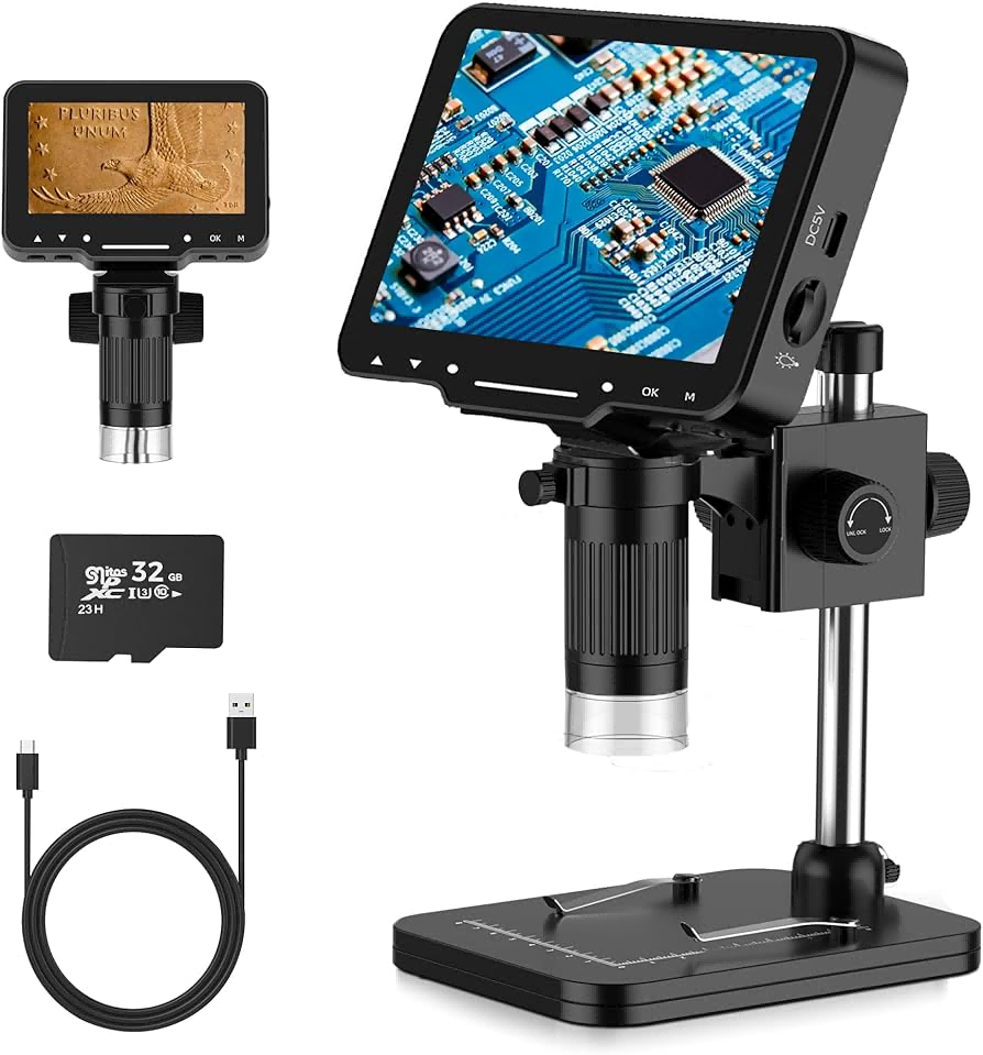
Digital USB and Stereo Microscopes:
These microscopes reveal solder bridges, lifted or misaligned parts, and incomplete wetting that are invisible to the naked eye. Shadow-free LED ring lighting reduces eye and neck strain during extended assembly sessions, allowing precise inspection over hours of manual placement.
-
Consumables:
High-quality flux pens enhance solder wetting and improve joint formation. Desoldering braid or solder wick allows the removal of excess solder or accidental bridges efficiently. Isopropyl alcohol cleans residual flux and leaves a professional, factory-ready finish.
Combining optical inspection with the correct consumables ensures each joint meets reliability standards. Proper inspection gear guarantees placement accuracy, detects microscopic defects, and maintains consistent solder quality. Investing in a digital microscope and high-quality liquid tools improves efficiency, reduces rework, and increases first-pass yield for hand-assembled PCBs.
How to Build a Complete Manual Pick and Place Toolkit
Assemble a reliable manual pick and place toolkit, starting with precision tweezers and vacuum pens. Add thermal tools such as a hot air rework station or SMT reflow hot plate. Include optical inspection gear, such as USB or stereo microscopes, for defect detection.
Flawless solder paste application forms the foundation of frustration-free manual assembly. A perfectly printed board holds components securely, and tackiness allows parts to self-align during reflow due to surface tension.
Ordering a precision frameless stencil alongside prototype boards from JLCPCB removes the most difficult step of hand soldering. Upgrade prototyping workflow today by visiting the JLCPCB Stencil Service Pageto add a frameless stencil to the next PCB order for just $3.
Choose from Framed/Frameless, Electropolishing, Nano-coating, Step-Stencils, SMD Glue Stencil and more. Starting at $3. No MOQ. 12-Hour production.
Get $11 Coupon Now >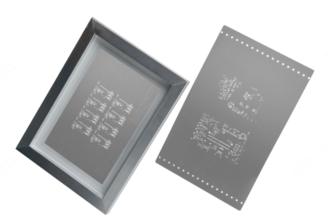
Frequently Asked Questions about Manual Pick and Place Tools
What tools are essential for manual pick and place assembly?
Precision tweezers, anti-static vacuum pens, a hot air rework station or SMT reflow hot plate, and USB or stereo microscopes form the essential toolkit. Consumables like flux pens, solder wick, and Isopropyl Alcohol complete the setup.
How do frameless stencils improve component placement?
Frameless stencils deposit solder paste evenly across PCB pads, preventing sliding, bridging, or misalignment. The flat paste holds parts securely and allows self-alignment during reflow, improving first-pass yield and consistent solder joint quality.
What mistakes do beginners make with manual pick and place?
Common errors include uneven paste application, misaligned components, bent pins from tweezers, and overheating components during reflow. Using proper stencils, tweezers, vacuum pens, and controlled heating reduces these defects.
How does paste volume affect solder joint quality?
Excess solder paste causes bridging between pads, while insufficient paste produces weak joints or tombstoning. Correct stencil thickness and consistent swipe techniques control paste volume.
Building a reliable manual pick and place toolkit is about combining precision handling, accurate paste application, and controlled thermal processes. By selecting the right tools for inspection and assembly, engineers can minimize human error and ensure that every prototype board meets high reliability standards. Ultimately, professional-grade results at the bench are achieved through the synergy of quality tools and a disciplined SMT workflow.
Keep Learning
Manual Pick and Place: A Cost-Effective SMT Alternative
Key Takeaways for Manual Pick and Place Manual pick and place uses a hand-held vacuum wand and positioning stage to place SMD components by hand, replacing tweezers in prototype assembly. It is most cost-effective for production runs of 1 to 50 boards, where an automated SMT pick-and-place machine cannot justify its $10,000+ setup cost. A complete manual workstation runs $300 to $500, compared with $10,000+ for an entry-level automated pick and place machine. SMT stencil quality is the single largest ......
Hot Air Surface Mount Soldering: A Step-by-Step Guide
Key Takeaways Heat Control Is Everything: Hot air SMD soldering delivers uniform heat across all pads simultaneously, eliminating the lifted pads and cold joints common with iron-based soldering of fine-pitch components. Airflow Kills Small Parts: Set airflow to just 10–20% for 0402/0201 passives to avoid the Bernoulli Effect that turns tiny resistors into projectiles. Stencil Precision Prevents Tombstoning: A precision-cut SMT stencil deposits equal paste volume on both pads, balancing surface tensio......
Solder Paste Printing Defects: How Precision Stencils Prevent Assembly Failures
Key Takeaways 70% Rule: Approximately 70% of SMT defects originate from the solder paste printing stage, making it the most critical process to optimize. Root Causes: Defects like bridging, insufficient paste, misalignment, and slumping are caused by stencil tension, process parameters (pressure, speed), and paste chemistry/environment. Area Ratio Matters: Maintaining an aperture Area Ratio (AR) above 0.66 (per IPC-7525) is essential to ensure proper paste transfer efficiency and prevent chronic insuf......
Best Manual Pick and Place Tools for Precise PCB Assembly
While fully automated robotic SMT lines handle mass production efficiently, every hardware innovation begins on a workbench. Engineers shifting from soldering large through-hole components to microscopic surface-mount devices (SMD) by hand quickly realize that precision and control are everything. Achieving factory-level assembly on your desk is absolutely possible with the right setup. This guide reviews the essential tool categories needed to build an effective prototyping workbench, covering precis......
How to Use a BGA Stencil for SMT Assembly and Reballing (Design & Process Guide)
Anyone who's spent time in a lab knows the look. You flip over a BGA chip and stare at the bottom. Flat. Featureless. No legs. No leads. Just a grid of tiny silver bumps. First thought? How the hell am I supposed to solder this? The Ball Grid Array (BGA) package is a trade-off. You get insane I/O density in a tiny footprint. But every single connection is hidden. You can't see them, and you can't poke them with an iron. Here's the thing I learned after lifting more pads than I'd like to admit: learnin......
Solder Bead Prevention: How PCB Stencil Design & Process Control Deliver Defect-Free Reflow Soldering
In modern SMT assembly, solder joint quality is determined long before the reflow oven starts—at the solder paste printing stage. When this step is not properly controlled, the consequences appear after reflow as tiny spherical solder particles scattered around component pads: solder beads. For engineers working with high-density assemblies, these defects are familiar and frustrating because they reappear whenever a process variable drifts outside its optimum range. This guide takes an engineering-fir......