
Efficiency in a Box: Unlocking the Physics of Plate and Spiral Heat Exchangers
11 min
- The Plate Heat Exchanger: A Thermal Sandwich
- The Physics of Flow: Counter-Current vs. Co-Current
- The Spiral Plate Heat Exchanger: Mastering the Messy
- Selection Strategy: Which Exchanger Fits?
- Operational Rigor: Maintenance and Safety
- Summary
- FAQ
In the world of thermal engineering, efficiency is king. While massive cooling towers and piping networks are the visible giants of industry, the real magic often happens inside much smaller, unassuming boxes.
These are Plate Heat Exchangers (PHEs) and their robust cousins, Spiral Plate Heat Exchangers (SPHEs). Originally introduced in 1923 by Dr. Richard Seligman, these devices represented a quantum leap from traditional “shell-and-tube” designs. Today, they are the unsung heroes of modern industry, celebrated for their ability to pack massive heat transfer capabilities into a surprisingly compact footprint.
But how do they work, and why are they so effective?
The Plate Heat Exchanger: A Thermal Sandwich
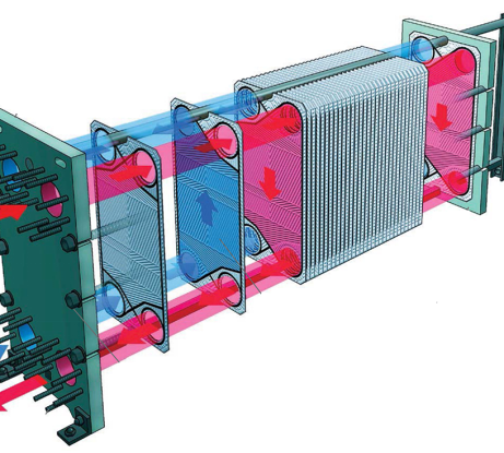
To understand a PHE, you must look past its heavy exterior frame to the “honeycomb” within. Essentially, the device is a compressed sandwich of corrugated metal plates.
Each plate acts as a thermal bridge. Hot fluid flows on one side of the plate, and cold fluid flows on the other. The secret lies in the corrugation—the chevron patterns stamped into the metal. These patterns aren’t just for structural strength; they are designed to induce turbulence.
Turbulence prevents the fluid from flowing smoothly (laminar flow). Instead, it mixes the fluid violently against the plate surface, maximizing heat transfer.
Think of it this way: imagine trying to cool your coffee. If you let it sit still, it cools slowly from the surface down. But if you stir it vigorously, you’re constantly bringing hot liquid from the center to the edges where it can release heat. The corrugations in a PHE do exactly this—they’re tiny mechanical agitators built into the metal itself.
The Materials Matter
The choice of plate material isn’t arbitrary. Stainless steel dominates for most applications, offering an excellent balance of thermal conductivity, corrosion resistance, and cost. But when dealing with highly corrosive fluids—think seawater or acidic chemicals—engineers turn to titanium or specialized alloys. Each material choice involves a careful calculation: thermal performance versus longevity versus budget.
The plates themselves are remarkably thin, often just 0.5 to 0.8 millimeters thick. This thinness is a feature, not a limitation. The thinner the barrier between hot and cold fluids, the faster heat can transfer. It’s the same reason a sheet of aluminum foil cools down almost instantly when you remove it from the oven, while a cast iron pan stays hot for minutes.
The Physics of Flow: Counter-Current vs. Co-Current
The efficiency of a PHE is largely dictated by the choreography of the fluids. While fluids can flow in the same direction (co-current), the most effective arrangement is pure counter-current flow, where hot and cold fluids move in opposite directions.
Why does direction matter?
Maintained Gradient: Counter-current flow maintains a consistent temperature difference between the two fluids throughout the entire length of the unit.
The 1°C Advantage: This allows PHEs to achieve temperature approaches (the difference between the exiting hot fluid and entering cold fluid) as close as 1°C. Compare this to the 5–10°C typical of older shell-and-tube units, and the efficiency gains become obvious.
Here’s where the physics gets beautiful. In co-current flow, both fluids enter at one end and exit at the other. The temperature difference starts high but rapidly decreases as the fluids approach thermal equilibrium. It’s like two runners starting at different speeds but gradually matching pace—eventually, there’s little advantage to be gained.
Counter-current flow, however, is like having runners on a track moving in opposite directions. At every point along the path, there’s a fresh temperature differential. The cold fluid entering at one end immediately encounters the nearly-cooled hot fluid exiting at that point. Meanwhile, at the opposite end, the fresh hot fluid meets the now-warmed cold fluid. This creates a consistent driving force for heat transfer along the entire length of the exchanger.
The mathematics bears this out. The log mean temperature difference (LMTD)—the key parameter engineers use to design these systems—is significantly higher in counter-current arrangements, sometimes by a factor of two or more.
The Spiral Plate Heat Exchanger: Mastering the Messy
Standard plates are excellent for clean water or oil. But what happens when you need to heat sewage, sludge, or viscous slurries? The narrow channels of a standard PHE would clog instantly.
Enter the Spiral Plate Heat Exchanger (SPHE).
Instead of a stack of distinct plates, an SPHE consists of two long metal strips rolled into a continuous, tight spiral. This creates two single, long concentric channels. Picture a cinnamon roll, but instead of dough and cinnamon, you have steel and flowing fluids.
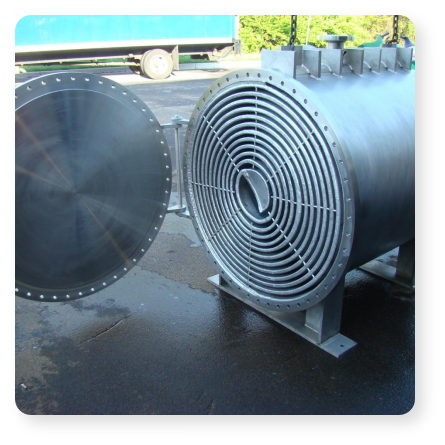
The Self-Cleaning Effect
The SPHE possesses a brilliant, unintended feature of physics: it is self-cleaning.
Single Channel Dynamics: Because there is only one path for the fluid, if a deposit or blockage forms, the local pressure behind that blockage increases.
The Flush: This pressure build-up naturally increases the fluid velocity at that specific spot, “flushing” the deposit away before it creates a permanent clog.
Furthermore, the concentric flow utilizes centrifugal forces to help keep solids in suspension, preventing them from settling on the walls.
This self-cleaning mechanism is a testament to clever engineering exploiting natural physics. In a multi-channel system like a standard PHE, if one channel clogs, the fluid simply redistributes to the other open channels. The blockage stays put and worsens over time. But in an SPHE’s single channel, there’s nowhere else to go—the system must confront the blockage directly, and physics naturally resolves it.
The spiral geometry also creates a secondary advantage: the constant curvature induces what fluid dynamicists call “Dean vortices”—small rotating flows perpendicular to the main flow direction. These vortices act like tiny scrub brushes, continuously sweeping the channel walls and preventing deposits from gaining a foothold.
Real-World Applications
Walk into a modern wastewater treatment plant, and you’ll likely find SPHEs doing the heavy lifting. They heat biological digesters, recover heat from sludge streams, and handle fluids that would make a standard exchanger weep. The pulp and paper industry relies on them too, where black liquor—a viscous, particle-laden byproduct of wood processing—needs to be heated as part of the chemical recovery process.
Selection Strategy: Which Exchanger Fits?
Selecting the right exchanger is a balance of fluid dynamics and spatial constraints. Based on engineering guidelines, here is how professionals choose between the two:
| Feature | Choose Plate (PHE) When… | Choose Spiral (SPHE) When… |
| Fluid Type | Fluids are clean, low viscosity, and free of solids. | Fluids are “difficult”—high viscosity, sludge, or slurries. |
| Efficiency Goal | You need extreme precision (temperature approach <5°C). | You need to prevent fouling/clogging. |
| Space | Floor space is tight; you need maximum power in a small box. | You have vertical space; structural integrity is priority. |
| Flexibility | You may need to add capacity later (just add more plates). | You need easy maintenance (open one cover to see the whole channel). |
The decision tree extends beyond this table, though. Consider pressure: PHEs excel at lower pressures but can struggle above 25 bar in standard configurations. SPHEs, with their welded construction, can handle significantly higher pressures with ease.
Then there’s the question of temperature cross. In some industrial processes, you need the cold fluid to exit hotter than the hot fluid enters (after it’s been cooled). This thermal crossing is trivially easy in counter-current plate exchangers but geometrically impossible in many other designs.
Operational Rigor: Maintenance and Safety
No technology is maintenance-free. Over time, “fouling” (the accumulation of unwanted material) becomes the primary enemy of heat transfer.
To keep these units running, engineers must adhere to strict protocols:
The “A-Dimension” Check: This is the specific tightening distance between the frame plates. It must match the nameplate exactly. - Too tight? You crush the metal plates. - Too loose? The unit leaks.
The Tell-Tale Vents: Gaskets are designed with safety vents. If a gasket fails, fluid drips externally first. This is a deliberate design feature to warn operators before the hot and cold fluids cross-contaminate.
Data as Diagnostics: Operators don’t just guess when to clean; they watch the physics. A gradual increase in pressure drop is the surest mathematical sign that internal fouling is restricting flow, signaling that it is time for Cleaning-In-Place (CIP) or a full pressure wash.
Modern facilities take this data-driven approach even further. Continuous monitoring systems track not just pressure drop, but also thermal efficiency in real-time. A PHE might be processing thousands of liters per hour with only a 3°C approach when new. As fouling accumulates, that approach might creep up to 4°C, then 5°C. Long before the unit fails catastrophically, the data whispers a warning: it’s time for maintenance.
The cleaning process itself is a careful dance. Chemical cleaning must be aggressive enough to dissolve deposits but gentle enough not to attack the metal plates or degrade the gaskets. Typically, operators cycle through acidic cleaners (to dissolve mineral scales), alkaline cleaners (to attack organic deposits), and finally sanitizers. Each cycle involves specific temperatures, flow rates, and contact times—there’s no room for improvisation.
The Hidden Economics
Here’s what makes these devices truly revolutionary: they pay for themselves. A well-designed PHE can recover heat that would otherwise be wasted, reducing energy consumption by 30% or more in some applications. In a large industrial facility, that translates to millions of dollars saved annually.
Consider a dairy processing plant. Milk arrives cold and must be pasteurized at high temperature, then cooled again for packaging. Without heat recovery, you’d need massive heaters and massive chillers running continuously. But with PHEs, the outgoing hot pasteurized milk preheats the incoming cold raw milk. Energy that would have been dumped to the atmosphere is instead recycled within the process. The capital cost of the heat exchanger is often recovered within a year or two.
Summary
Whether it is the high-turbulence efficiency of the PHE or the rugged, self-cleaning nature of the SPHE, these devices represent a triumph of engineering over simple plumbing. By manipulating surface area, flow direction, and pressure, they allow industries to recover energy that would otherwise vanish into thin air.
The next time you drink pasteurized milk, enjoy heating from a district system, or benefit from any of countless industrial processes, remember: somewhere in that supply chain, there’s likely a nondescript metal box doing thermal gymnastics. These heat exchangers don’t inspire awe like skyscrapers or spacecraft, but they quietly enable the modern world—one precisely controlled degree at a time.
In an era where energy efficiency isn’t just economical but environmental, the humble heat exchanger has evolved from industrial workhorse to climate hero. Every kilowatt-hour of waste heat recovered is one less kilowatt-hour that must be generated, and one less contribution to our carbon footprint. Efficiency, as it turns out, isn’t just king—it’s the future.

FAQ
Q: What makes plate heat exchangers more efficient than traditional shell-and-tube designs?
A: Plate heat exchangers achieve superior efficiency through two key features: corrugated plates that create turbulence (maximizing heat transfer by constantly mixing fluid against the surface), and counter-current flow that maintains a consistent temperature difference throughout the unit. This allows them to achieve temperature approaches as close as 1°C, compared to 5–10°C in older designs.
Q: When should I choose a spiral plate heat exchanger over a standard plate heat exchanger?
A: Choose a spiral plate heat exchanger when dealing with "difficult" fluids—high viscosity liquids, sludge, slurries, or fluids containing solids. The spiral design's single continuous channel creates a self-cleaning effect where pressure naturally flushes away blockages, and centrifugal forces keep particles in suspension. Standard plate exchangers work best with clean, low-viscosity fluids.
Q: How do heat exchangers pay for themselves economically?
A: Heat exchangers recover waste heat that would otherwise be lost, reducing energy consumption by 30% or more in many applications. For example, in dairy processing, hot pasteurized milk preheats incoming cold milk, eliminating the need to run massive heaters and chillers continuously. In large industrial facilities, this translates to millions in annual savings, often recovering the capital cost within one to two years.
Keep Learning
Simultaneous Dual-Frequency Induction Heating: When One Frequency Forces the Wrong Compromise
Key Takeaways One frequency, one compromise: When geometry demands both deep bulk heating and controlled surface gradients simultaneously, a single frequency forces an unacceptable trade-off—dual-frequency widens the process window. Give each channel a role: Assign the lower frequency to bulk penetration and the higher frequency to surface shaping. Structured recipe development follows naturally from this separation. Validate with metrics, not opinions: Dual-frequency is justified only when controlled......
Power Supplies by Application Family: Joining, Mass Heating, and Strip Processing
Key Takeaways Joining operations (brazing, soldering, bonding) demand higher frequencies and matching flexibility to handle variable coil coupling and precision surface heating. Mass heating lines (billets, bars, slabs) prioritize continuous duty, efficiency, and ruggedness at high power levels with multi-coil zone control. Strip processing requires architectures that separate control electronics from high-frequency inverter modules to cope with harsh installation environments. Specifying only kW and ......
Simultaneous Dual-Frequency Induction Power: When One Frequency Forces the Wrong Compromise
Key Takeaways Dual-frequency is justified by robustness, not complexity: It should only be adopted when a single frequency forces an unacceptable compromise between surface and bulk heating requirements. Give each frequency a defined role: Assign the lower frequency to bulk heating/penetration and the higher frequency to surface shaping—then develop recipes one variable at a time. The combining network is the engineering center of gravity: Frequency-selective coupling paths, thermal rating for worst-c......
Applying Induction Power Supplies in the Real World: Constraints That Decide Uptime and Quality
Key Takeaways Application constraints dominate real-world performance: Two induction systems with identical kW ratings can behave very differently depending on cable length, cooling water temperature, dust levels, and fixture repeatability. Design for drift, not for perfect day one: Coils deform, filters clog, sensors drift, and connectors loosen under thermal cycling. Baseline monitoring during commissioning is essential. Mechanical repeatability often beats control complexity: Improving fixturing an......
Medium- and High-Frequency Transformers in Induction Systems: Design Drivers Engineers Should Actually Care About
Key Takeaways Not Passive: Transformers set the electrical operating point for the entire induction station—coil voltage, current, capacitor stress, and inverter margin all depend on transformer choice. Frequency Effects: At higher frequencies, winding losses and stray capacitance dominate; a transformer that looks fine on turns ratio can fail a duty-cycle test if loss distribution is wrong. Placement Matters: Moving the transformer and capacitor bank closer to the coil reduces high-frequency loop len......
Load Matching in Induction Heating: Designing for Stability, Efficiency, and Real-World Variation
Key Takeaways Dynamic Load: Induction heating loads are not fixed—coupling, material properties, and temperature all shift impedance during operation, making matching a continuous design challenge. Q Factor Matters: High-Q loads can produce large circulating currents and capacitor stress even at modest delivered kW; design for the worst-case kVA, not just power. Discrete Ranges Win: Transformer taps and capacitor steps that cover discrete matching ranges outperform a single broad-range configuration f......