
The High-Performance Athletes of Engineering: A Deep Dive into Compact Heat Exchangers
11 min
- The Science of “Compactness”
- Anatomy of Efficiency: The Two Main Architectures
- Mastering the Boundary Layer
- Designing the Puzzle: The ε-NTU Method
- The Achilles Heel: Fouling
- Real-World Applications: Where Compactness Counts
- Summary: Choosing the Right Tool
- The Bottom Line
- Q&A
In the vast world of thermal engineering, traditional shell-and-tube heat exchangers are the heavy lifters—massive, industrial giants found in oil refineries and power plants. Some of these behemoths weigh as much as a locomotive and occupy the footprint of a small house. But when space is tight and weight is the enemy—say, in a jet engine cruising at 40,000 feet or a liquefied natural gas terminal on a floating platform—engineers turn to a different breed of machine: the Compact Heat Exchanger.
Think of them as the elite sprinters of the thermal world. Where traditional exchangers trade brute size for reliability, compact units are precision instruments—designed for aerospace, cryogenics, and automotive cooling. These units are defined by their ability to pack an incredible amount of performance into a tiny footprint. A compact exchanger can deliver the same thermal duty as a conventional unit five times its size.
The Science of “Compactness”
What exactly makes a heat exchanger “compact”? It isn’t just a marketing term for “small”; it is a rigorous engineering definition based on Area Density (β).
Area density measures how much heat transfer surface area is squeezed into a specific volume. To officially qualify as a compact heat exchanger (gas-side), the unit must have an area density greater than 700 m²/m³. For liquid-side applications, the threshold is even higher: 400 m²/m³ or more.
To put that number in perspective, consider a conventional shell-and-tube exchanger—it might achieve an area density of only 100-200 m²/m³. Now let’s look at nature’s ultimate compact exchanger: the human lung.
Your lungs achieve an area density of nearly 20,000 m²/m³—cramming roughly 70 square meters of gas-exchange surface (about the size of a tennis court) into the volume of two footballs. That staggering efficiency inspired the very geometries engineers use today.
Compact heat exchangers mimic this biological brilliance using specific geometric strategies:
• High Surface Density: Engineers use fins and narrow passages to maximize the contact area between the fluid and the metal. In some aircraft heat exchangers, there can be over 800 fins per meter.
• Microscopic Channels: The flow channels often have a hydraulic diameter (Dₕ) of less than 5 mm—some advanced microchannel designs go below 1 mm. For comparison, a typical shell-and-tube exchanger uses tubes with diameters of 15-25 mm.
• The Trade-off: While these units save massive amounts of space and weight (critical when every kilogram costs fuel), their tiny channels make them hypersensitive to clogging (fouling) compared to their heavy industrial cousins. A particle that would sail harmlessly through a conventional exchanger can choke a compact unit.
Anatomy of Efficiency: The Two Main Architectures
Compact exchangers generally fall into two architectural families. If you own a car or an air conditioner, you are likely using one right now.
The Tube-Fin Exchanger
These are the workhorses of daily life—from car radiators to household air conditioning units. Walk up to your car’s grille and peer inside: that aluminum lattice behind it is a tube-fin exchanger working to keep your engine from melting.
They consist of tubes carrying high-pressure fluid (coolant, refrigerant, or oil), which pass through a stack of metal sheets (fins) that handle the air side.
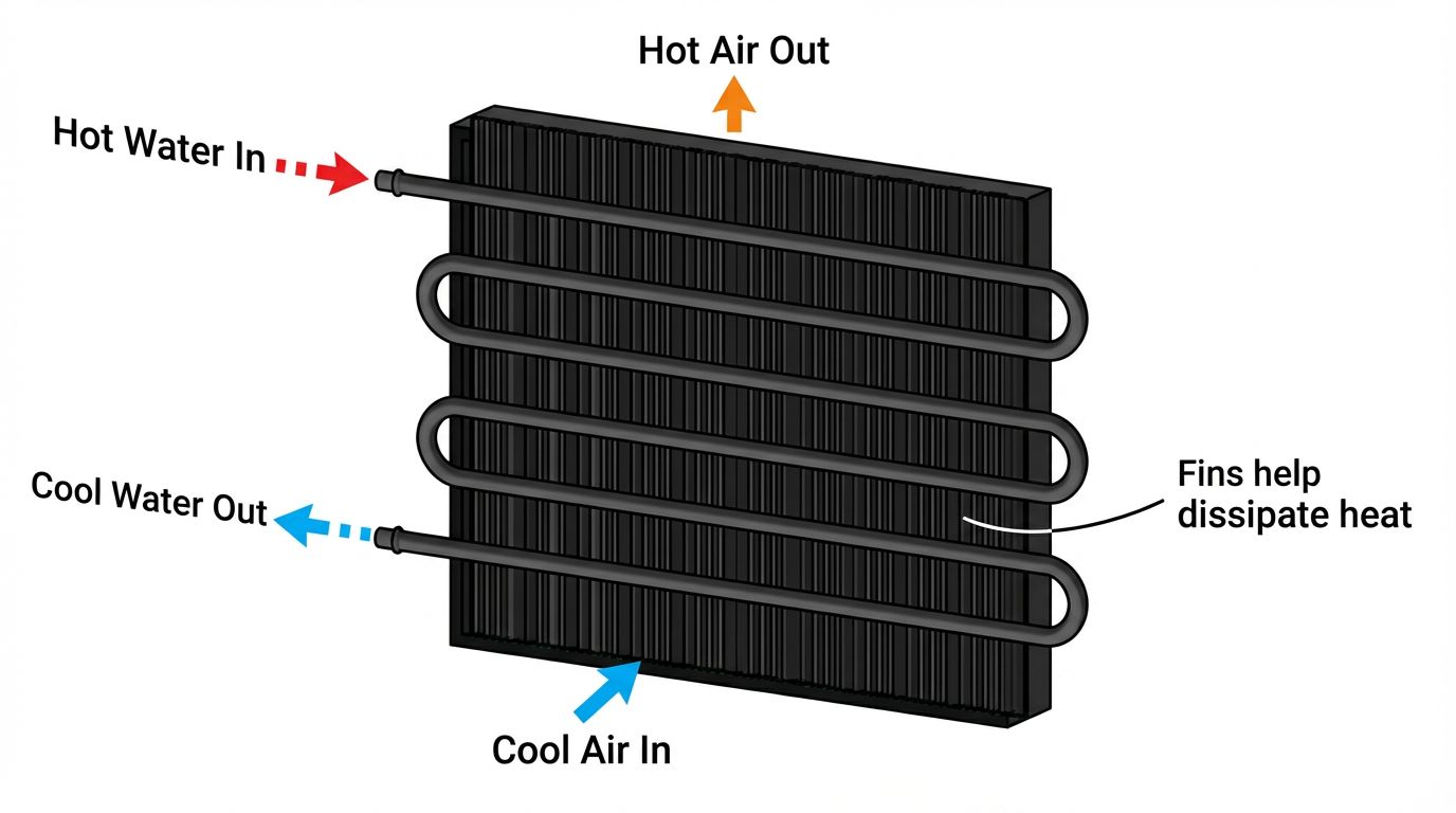
How it works: The fins act as extensions of the tubes, grabbing heat from the air and funneling it into the fluid (or vice versa). Because air is a poor conductor, the fins multiply the effective surface area by 10-20 times compared to bare tubes alone.
Construction: Fins are mechanically expanded or brazed onto the tubes to ensure perfect thermal contact. Even a microscopic air gap between fin and tube would create thermal resistance that ruins performance—engineers call this “contact resistance.”
Materials: Usually copper or aluminum for their superior thermal conductivity (copper: 400 W/m·K, aluminum: 237 W/m·K, versus steel at only 50 W/m·K). The choice depends on cost, corrosion environment, and weight constraints.
The Plate-Fin Heat Exchanger (PFHE)
If the Tube-Fin is a radiator, the Plate-Fin is a complex thermal sandwich—and the technology that makes modern cryogenics possible.
It consists of alternating layers of corrugated fins and flat parting sheets (separating the different fluid streams), all brazed into a single, solid block in a massive furnace. The entire assembly is heated to 600°C in a controlled atmosphere, fusing it into what is essentially a single metal crystal.
The “Sandwich” Structure: This design creates a rigid pressure vessel capable of handling multiple fluid streams simultaneously—sometimes four or five different fluids in a single unit, each at different temperatures and pressures. This is impossible with conventional exchangers.
The Superpower: They are essential in cryogenics (like air separation plants), where they manage temperature differences between fluids as small as 1°C. In a liquefied natural gas (LNG) facility, these exchangers cool methane from ambient temperature down to -162°C—a span of nearly 180 degrees—while simultaneously warming nitrogen streams that would otherwise be wasted.
The Challenge: Because the entire block is brazed together, there’s no way to take it apart. If something goes wrong internally, the entire exchanger becomes scrap metal. This is why quality control during manufacturing is absolutely critical.
Mastering the Boundary Layer
The “magic” of compact exchangers isn’t just in their size; it’s in how they manipulate fluid dynamics at the microscopic level.
In a smooth pipe, a stagnant layer of fluid—called the boundary layer—forms against the wall. This layer acts like a thermal blanket that insulates the surface and slows down heat transfer. It’s the reason your coffee cools faster when you stir it—stirring breaks up that insulating layer.
Compact exchangers are designed to ruthlessly disrupt this layer, over and over again.
Engineers use geometries like offset strip fins to periodically “restart” the boundary layer:
1. The fluid hits the leading edge of a fin
2. It creates a turbulent wake, violently mixing the fluid
3. The boundary layer breaks and reforms—thinner than before
4. Heat transfer coefficient (h) spikes dramatically
This happens hundreds of times per second as the fluid zigzags through the exchanger. The result? Heat transfer coefficients 3-5 times higher than in smooth tubes.
This performance is calculated using two dimensionless correlations derived from thousands of wind tunnel experiments:
• The j factor (Colburn factor): Measures thermal performance—how effectively the surface transfers heat
• The f factor (Friction factor): Measures hydraulic resistance (the pressure drop “cost” of that performance)
There’s always a trade-off: Higher j means better heat transfer, but also higher f—meaning you need bigger pumps and more energy to push the fluid through. Optimal design is about finding the sweet spot.
Designing the Puzzle: The ε-NTU Method
Designing these units is an iterative puzzle of matching high heat loads with strict pressure limits—often with competing constraints that seem mathematically impossible to satisfy.
While simple industrial exchangers use the LMTD (Log Mean Temperature Difference) method, compact exchangers usually require the ε-NTU (Effectiveness-Number of Transfer Units) method.
Why?
Because compact exchangers often operate at effectiveness levels exceeding 90%—meaning they extract 90% of the theoretically maximum possible heat from a fluid stream. When you are trying to squeeze every last joule of energy out of a system (critical in aerospace and cryogenics), the ε-NTU method offers the precision needed to relate heat transfer capacity directly to the maximum possible temperature change.
The method works like this:
• ε (effectiveness): The ratio of actual heat transfer to the maximum possible heat transfer
• NTU (Number of Transfer Units): A dimensionless parameter representing the “size” of the heat exchanger relative to the fluid flow rates
• The relationship between them depends on the flow arrangement (counterflow, crossflow, etc.)
Engineers iterate through designs, tweaking fin spacing, channel heights, and flow arrangements until they hit the target thermal duty while staying under pressure drop limits—often using computational fluid dynamics (CFD) software running for hours on powerful computers.
The Achilles Heel: Fouling
The greatest weakness of the compact heat exchanger is its sensitivity to debris. With flow passages smaller than 5 mm, a compact unit is essentially a very expensive filter—and it will perform that filtering function whether you want it to or not.
If the fluid contains dirt, algae, scale, corrosion products, or biological growth, the channels can block catastrophically—a phenomenon known as fouling. Pressure drop skyrockets, flow rate plummets, and thermal performance collapses.
The consequences can be severe:
• In power plants, a fouled exchanger can force an emergency shutdown
• In aircraft, it can trigger overheating alarms
• In chemical plants, it can create dangerous temperature excursions
Mitigation: Upstream filtration is mandatory—typically 100-micron filters or finer. Water treatment (to prevent scaling and biological growth) is equally critical. Some facilities install automated backflushing systems that periodically reverse flow to dislodge deposits.
Warning: In industries involving “dirty” fluids (like heavy crude oil or untreated river water), engineers usually avoid compact brazed units unless strict filtration is guaranteed. The maintenance headache simply isn’t worth the space savings.
Real-World Applications: Where Compactness Counts
The benefits of compact exchangers aren’t just theoretical—they enable technologies that would otherwise be impossible:
• Aircraft engines: Jet fuel/oil coolers must fit inside tight nacelles while withstanding vibration and extreme temperature swings. A compact exchanger weighing 10 kg replaces what would be a 50 kg conventional unit.
• Offshore platforms: Space on an oil rig is worth its weight in gold. Compact exchangers for gas cooling can save 60-70% of the footprint.
• Automotive: Modern turbocharged engines run intercoolers (air-to-air exchangers) to cool compressed intake air, boosting power and efficiency. These must fit in the front bumper—impossible with conventional designs.
• Cryogenic air separation: Plants producing industrial oxygen and nitrogen use plate-fin exchangers operating at -190°C. They’re the unsung heroes that supply hospitals with medical oxygen and semiconductor fabs with ultra-pure nitrogen.
Summary: Choosing the Right Tool
How do engineers decide between a compact unit and a massive shell-and-tube unit? It comes down to balancing physics and economics—and understanding which constraints dominate your specific application.
| Feature | Compact Exchanger (Plate-Fin/Tube-Fin) | Tubular Exchanger (Shell-and-Tube) |
| Best For | Gases, clean liquids, cryogenics | Fouling fluids, high-pressure steam, slurries |
| Space/Weight | Critical (Aerospace, Offshore) | Not critical (Land-based plants) |
| Thermal Performance | Effectiveness >90% achievable | Typically 60-80% effectiveness |
| Maintenance | Difficult to clean (often impossible to rod-out) | Easy to disassemble and clean mechanically |
| Pressure Drop | Higher (narrow channels) | Lower (larger flow areas) |
| Cost | Lower material cost, higher manufacturing complexity | Higher material cost, standard manufacturing |
| Fouling Tolerance | Very low—requires clean fluids | High—can handle particulates and scaling |
The Bottom Line
Compact heat exchangers are marvels of surface area density, allowing modern technology—from smartphones to spacecraft—to remain light and efficient. They represent a triumph of engineering: taking inspiration from nature (the human lung), mastering fluid dynamics (boundary layer control), and pushing manufacturing to its limits (brazed microscopic channels).
However, they demand respect—specifically regarding clean fluids and precise design. Use them in the right application, and they’re transformative. Use them in the wrong one, and you’ve built an expensive paperweight.
In the end, the compact heat exchanger reminds us that in engineering, as in evolution, constraints breed innovation. When you can’t build bigger, you build smarter.

Q&A
Q1: What makes a heat exchanger "compact"?
A heat exchanger is officially compact when it achieves an area density (β) greater than 700 m²/m³ for gas-side applications or 400 m²/m³ for liquid-side applications. This means it packs significantly more heat transfer surface area into a given volume compared to traditional shell-and-tube exchangers (which typically achieve only 100-200 m²/m³). The result: a compact unit can deliver the same thermal performance as a conventional exchanger five times its size.
Q2: Why are compact heat exchangers so sensitive to fouling?
Compact exchangers use extremely narrow flow channels—often less than 5 mm in hydraulic diameter, with some microchannel designs below 1 mm. While this maximizes heat transfer efficiency, it also means that dirt, scale, or debris that would pass harmlessly through a conventional exchanger can easily clog these tiny passages. When fouling occurs, pressure drop skyrockets and thermal performance collapses, which is why upstream filtration and clean fluids are absolutely critical.
Q3: When should I choose a compact exchanger over a traditional shell-and-tube design?
Choose compact exchangers when space and weight are critical constraints (aerospace, offshore platforms, automotive applications) and you're working with clean fluids or gases. They excel in cryogenic applications and can achieve thermal effectiveness above 90%. However, stick with traditional shell-and-tube exchangers if you're dealing with fouling fluids, need easy maintenance access, or require lower pressure drops—especially in land-based industrial plants where space isn't a limiting factor.
Keep Learning
How Transparent Graphene Heaters Clear Fogged Glass
Key Takeaways Atom-thin transparency: A single graphene layer transmits about 97.7% of visible light, while five stacked layers still pass roughly 87.3%, making the heater nearly invisible on glass or plastic. Fast, controllable heating: A monolayer device reaches its target temperature with a thermal time constant of only about 6–7 seconds, and input power can be adjusted to hold temperatures from 38 °C up to around 80 °C. Efficiency advantage: Graphene heaters achieved higher temperatures at the sam......
Process Control, Monitoring, and Quality Assurance in Induction Heating: Reducing Risk Without Cutting Every Part
Key Takeaways Separate control from monitoring: A control system executes the recipe; a monitoring system independently verifies what actually happened. Independence turns logs into evidence. Monitor intermediate variables: You can't measure fatigue strength inline, but you can measure delivered kW, frequency stability, position, and quench variables—then compare each cycle to a validated "good envelope." Signature monitoring beats single thresholds: Time-series signatures capture ramps, holds, and tr......
Cooling Induction Power Supplies: Designing the Thermal System That Protects Your Electrical System
Key Takeaways Cooling is a first-class subsystem: Many "electrical" failures in induction lines are actually thermal problems—drifting water temperature, clogged filters, or unbalanced branch flow. Measure at the branch, not the header: A healthy header can mask a starved branch. Branch flow to the highest-loss modules is the single most useful cooling measurement. Trend cooling like a process variable: Baseline flow, temperature, and filter pressure drop during commissioning, then trend them to turn ......
Independent Frequency and Power Control in Induction Inverters: Turning Frequency Back Into a Process Variable
Key Takeaways Frequency as a process variable: Independent frequency and power control decouples resonance supervision from kW regulation, letting engineers set frequency based on process physics rather than control mechanics. Measurable validation: Prove independent control with three commissioning tests—fixed-frequency power steps, fixed-kW frequency sweeps, and coupling variation stability. Production consistency: Stable frequency improves recipe portability, reduces hidden process changes, and mak......
Simultaneous Dual-Frequency Induction Heating: When One Frequency Forces the Wrong Compromise
Key Takeaways One frequency, one compromise: When geometry demands both deep bulk heating and controlled surface gradients simultaneously, a single frequency forces an unacceptable trade-off—dual-frequency widens the process window. Give each channel a role: Assign the lower frequency to bulk penetration and the higher frequency to surface shaping. Structured recipe development follows naturally from this separation. Validate with metrics, not opinions: Dual-frequency is justified only when controlled......
Power Supplies by Application Family: Joining, Mass Heating, and Strip Processing
Key Takeaways Joining operations (brazing, soldering, bonding) demand higher frequencies and matching flexibility to handle variable coil coupling and precision surface heating. Mass heating lines (billets, bars, slabs) prioritize continuous duty, efficiency, and ruggedness at high power levels with multi-coil zone control. Strip processing requires architectures that separate control electronics from high-frequency inverter modules to cope with harsh installation environments. Specifying only kW and ......