
Beyond Water: The Engineering of Air-Cooled Heat Exchangers
13 min
- The Water Crisis That Changed Everything
- The Core Principle: Overcoming Air’s Limitations
- Anatomy of a “Fin-Fan”
- Air vs. Water: The Trade-offs
- Thermodynamic Engineering and Layouts
- Operational Intelligence: Surviving the Extremes
- The Economics of Air
- Conclusion
- FAQ
- Q1: What's the main difference between a regenerator and a recuperator?
- Q2: Why aren't regenerators used in hospitals or food processing plants?
- Q3: How much energy can regenerators actually save?
In the vast landscape of industrial engineering, cooling is a non-negotiable requirement. Whether refining oil, generating power, or processing chemicals, removing excess heat is essential for safety and efficiency. Traditionally, this meant water—oceans of it. Huge cooling towers and massive water treatment facilities have long been the industry standard.
But what happens when you build a plant in an arid desert, or where environmental regulations strictly limit thermal pollution in local waterways?
Enter the Air-Cooled Heat Exchanger (ACHE). Frequently referred to in the industry as a “fin-fan,” this technology represents a shift from hydro-centric cooling to aero-centric thermodynamics. It is, in essence, a colossal version of the radiator in your car or the heat sink on your computer’s CPU, designed to handle the rigorous demands of heavy industry.
The Water Crisis That Changed Everything
Consider the Secunda coal-to-liquids plant in South Africa, one of the world’s largest synthetic fuel facilities. Located in a water-stressed region, it operates hundreds of air-cooled heat exchangers that together reject enough heat to warm a small city. Without ACHEs, this plant—and the thousands of jobs and energy security it provides—simply couldn’t exist in its current location.
Or take the natural gas processing facilities scattered across the Middle Eastern deserts. Here, ambient temperatures regularly exceed 115°F, and freshwater is more precious than the hydrocarbons being processed. These plants rely entirely on air cooling, operating under conditions that would make traditional water-cooling systems economically absurd or outright impossible.
The shift to air cooling isn’t just about convenience—it’s about survival in a world where water scarcity is becoming the norm, not the exception.
The Core Principle: Overcoming Air’s Limitations
The fundamental challenge of an ACHE is physics. Water is an incredible coolant because it has a high heat capacity and thermal conductivity—roughly 25 times better than air at conducting heat away from a hot surface. Air, by comparison, is lazy. It doesn’t want to absorb heat, and when it does, it carries that heat away reluctantly.
To make air effective enough to cool boiling chemical processes, engineers cannot rely on simple contact. They must manipulate two variables: surface area and velocity.
Think of it this way: if you wanted to cool a hot cup of coffee, you could either blow gently on a very large surface (like pouring it into a wide, shallow bowl) or blow very hard on the cup itself. The first method is far more efficient. The same principle governs ACHE design—maximize the contact surface between hot metal and cool air.
Unlike shell and tube exchangers that facilitate liquid-to-liquid transfer, an ACHE works by forcing or inducing ambient air across a bundle of tubes carrying the hot process fluid. Because the heat transfer coefficient of air is so much lower than that of the liquid inside the tubes—typically 10 to 100 times worse—the surface area on the air side must be dramatically increased.
Anatomy of a “Fin-Fan”
To achieve the necessary cooling, ACHEs rely on a specific triad of components, each optimized through decades of industrial evolution:
1. The Finned Tube
The “fin” is the secret weapon of the ACHE. Standard 1-inch tubes are wrapped in aluminum fins, applied via tension winding (where a continuous strip of metal is helically wrapped under tension) or extrusion (where the fin and tube are bonded as a single piece). This increases the surface area significantly—typically packing 7 to 16 fins per every inch of tube length. On a single tube, this can transform 3 square feet of bare tube surface into 50 or even 100 square feet of finned surface. This extended surface grabs the heat from the tube wall and dissipates it into the passing air stream.
The choice of aluminum is deliberate. It’s lightweight, resists oxidation, and has excellent thermal conductivity (about 200 W/m·K)—nearly as good as copper but at a fraction of the weight and cost. In corrosive environments, stainless steel fins might be used, though this sacrifices some thermal performance for durability.
2. The Axial Flow Fan
These are not your average desk fans. Ranging from 4 to 12 feet in diameter, these massive impellers drive the system. Standing beneath one in operation is like facing into a hurricane—they can move 100,000 to 500,000 cubic feet of air per minute. They are typically composed of 4 to 6 blades made from aluminum or glass-reinforced plastic, each blade carefully shaped with an airfoil profile to maximize thrust while minimizing turbulence and noise.
Driven by electric motors (often 15 to 50 horsepower) via V-belts or gear drives, they generate the immense airflow required to strip heat from the fins. The engineering here is subtle: blade pitch (the angle of attack) must be optimized for the local air density, which changes with altitude and temperature. A fan designed for a coastal refinery won’t perform optimally at a mountain-top mining operation 8,000 feet above sea level.
3. Crossflow Configuration
The geometry is precise. The system utilizes a crossflow arrangement, meaning the air moves perpendicular to the tubes—imagine wind blowing across a forest of horizontal tree trunks. Inside the headers (the boxes at the ends of the tubes), baffles direct the liquid to make multiple passes back and forth, creating a serpentine flow path. This optimizes the fluid velocity—keeping it turbulent enough to ensure maximum heat transfer from the hot liquid to the tube wall—before it exits the unit.
A typical ACHE might force the process fluid through 4, 6, or even 8 passes. More passes mean higher heat transfer but also higher pressure drop, requiring more pumping energy. It’s a classic engineering trade-off.
Air vs. Water: The Trade-offs
Why choose air over water? It usually comes down to resource availability, operational costs, and environmental constraints.
| Feature | Air Cooling (ACHE) | Water Cooling |
| Resources | Independent: Uses ambient air; ideal for arid regions. | Dependent: Requires massive water source and treatment chemicals. |
| Maintenance | Low: No scaling or corrosion issues; 20-30% cheaper to maintain. | High: Prone to fouling, scaling, and biological growth. |
| Environment | Clean: No thermal pollution of rivers; no chemical disposal. | Impactful: Issues with “blowdown” water disposal and heating up waterways. |
| Performance | Variable: Performance drops on hot days (Dry-Bulb limitation). | Stable: Can cool to lower temperatures (Wet-Bulb approach). |
| Footprint | Large: Requires significant land area for airflow. | Compact: Higher efficiency allows for smaller units. |
| Capital Cost | Higher upfront: More material, larger structures. | Lower initial: Established technology, compact design. |
The performance difference deserves emphasis. Water cooling can achieve approach temperatures of 5-10°F above the wet-bulb temperature (the temperature reading from a thermometer covered in a water-soaked cloth). Air cooling is limited by the dry-bulb temperature—the actual ambient air temperature. On a 95°F summer day, an ACHE simply cannot cool a process stream below 95°F, whereas a water cooler might achieve 80°F or even lower. This fundamental thermodynamic limitation means ACHEs must be significantly larger to compensate.
Thermodynamic Engineering and Layouts
Designing an ACHE is a balancing act between thermal performance and hydraulic energy—you’re simultaneously solving a heat transfer problem and a fluid dynamics problem.
One major consideration is the Pressure Drop (ΔP). Pushing air through a dense bundle of finned tubes requires energy. The fins create turbulence—which enhances heat transfer but also creates resistance. The relationship between fan power and pressure is significant:
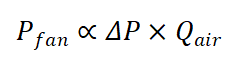
Where fan power is proportional to both the pressure drop and the volumetric flow rate of air. Engineers must ensure that the increased cooling provided by high-velocity air isn’t negated by the soaring electricity costs of running the fans. In a large refinery, ACHE fans might consume several megawatts of power—enough to run a small town. Over a 20-year lifespan, energy costs can exceed the initial equipment cost by a factor of three or more.
This is why fin density is carefully calculated. Too many fins per inch, and the air struggles to penetrate the bundle, requiring excessive fan power. Too few, and you need a physically larger (and more expensive) unit to achieve the same cooling.
The Shape of Cooling
While the Horizontal Layout is the standard workhorse—easy to access for maintenance but land-hungry—specialized shapes exist for specific needs:
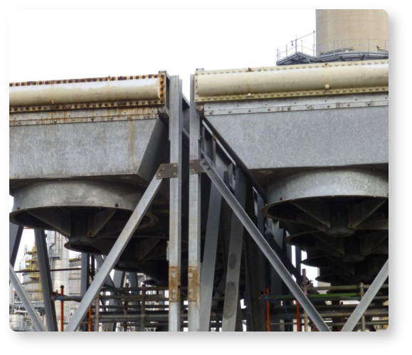
The A-Frame (Roof Type): Used extensively in power plants as steam condensers. The tube bundles are sloped at 45–60°, creating a roof shape that looks like a giant industrial tent. This allows condensed liquid to drain rapidly via gravity, preventing “water-logging” inside the tubes that would reduce heat transfer efficiency. It also reduces the ground footprint by nearly 50%, critical in space-constrained facilities. The downside? Maintenance crews need special access platforms and safety equipment to work on angled bundles.
Forced vs. Induced Draft: This fundamental choice determines where the fan sits. In forced draft units, fans push air up through the tube bundle from below. In induced draft, fans sit on top and pull air through. Induced draft creates more uniform airflow and keeps hot exhaust away from the fan motor (extending motor life), but if a tube leaks, process fluid can contaminate the fan. Forced draft is the safer choice for toxic or flammable services.
Operational Intelligence: Surviving the Extremes
ACHEs are exposed to the elements, making them sensitive to their environment in ways that enclosed water systems never experience. Real-world operation requires constant vigilance and clever engineering.
In the Frozen North
In climates dropping to -60°F, such as oil fields in Siberia or northern Canada, the risk isn’t overheating—it’s overcooling. Process fluids can freeze or turn into a viscous gel inside the tubes, potentially rupturing them when the ice expands. To combat this, engineers use Recirculation Chambers to mix warm exhaust air with frigid inlet air, maintaining a safe operating temperature.
Some systems employ louvers—movable shutters that can block airflow through sections of the bundle, much like closing vents in your house. On the coldest days, you might see an ACHE running with 70% of its surface blocked off, the fans barely turning, while in summer the same unit operates at full capacity.
Winter operation also introduces the bizarre problem of snow accumulation. A blanket of snow on top of a horizontal ACHE acts as perfect insulation, potentially causing overheating of the process fluid despite sub-zero ambient conditions.
In Dirty Environments
Dust, pollen, and insects can clog the fins, acting as an insulator and degrading performance by 20-30% or more. Cottonwood seeds, common in North America, are particularly notorious—they accumulate in massive drifts that can actually catch fire if they contact hot surfaces.
While high-pressure air or water washing can clean them, design choices matter. In dirty environments, engineers avoid serrated fins (which trap dirt like a filter) in favor of smooth fins with wider spacing. Some facilities install permanent spray systems that periodically mist the bundles, washing away accumulated debris.
Energy Efficiency: The VFD Revolution
Modern units utilize Variable Frequency Drives (VFDs), electronic controllers that vary the motor speed rather than running at constant RPM. Instead of running fans at 100% power constantly, VFDs allow the fans to slow down during cool nights or winters, drastically reducing power consumption.
The savings are dramatic because fan power varies with the cube of speed. Running a fan at 50% speed doesn’t just save 50% energy—it saves 87.5%. Over a year, this can represent hundreds of thousands of dollars in electricity costs for a large facility.
Advanced systems now incorporate weather forecasting into their control logic. If the system knows a cool front is arriving in six hours, it might pre-cool the process fluid while conditions are favorable, then throttle back when temperatures rise.
The Economics of Air
Here’s a reality that often surprises non-engineers: despite their lower thermal efficiency, ACHEs frequently win on total cost of ownership, particularly in water-scarce regions.
Consider a 100 MW refinery cooling duty. A water-based system might cost $2 million installed but require $500,000 annually for makeup water, treatment chemicals, and maintenance. An ACHE for the same duty might cost $4 million installed but only $150,000 annually for electricity and minimal maintenance. By year six, the ACHE is cheaper—and it continues to win for the next 20-30 years of operational life.
Environmental compliance adds another dimension. Many jurisdictions now impose strict limits on thermal discharge to waterways, or require expensive cooling towers to reduce this impact. Suddenly, “free” river water isn’t so free anymore.
Conclusion
The Air-Cooled Heat Exchanger is a testament to adaptive engineering. It acknowledges that while water is a superior coolant, it is a finite luxury our industrial world can no longer take for granted. By leveraging the principles of extended surface area and forced convection, ACHEs allow vital industrial processes to function in harmony with their local environment—whether that is a water-scarce desert or a frozen tundra.
The golden rule of ACHE design remains: “More surface area is always better than more airflow.” It is almost always better to build a slightly larger unit—adding another row of tubes, packing in a few more fins per inch—than to pay the energy cost of trying to force air through a small one at hurricane velocity.
As climate change intensifies water scarcity and environmental regulations tighten, the humble fin-fan will only grow more critical. It represents not just a different way to cool, but a different philosophy: work with what nature provides, even if it’s not ideal, rather than exhausting resources that may soon run dry.

FAQ
Q1: What's the main difference between a regenerator and a recuperator?
A recuperator (like a car radiator) continuously transfers heat through a metal wall separating hot and cold streams. A regenerator uses a porous solid matrix that alternates between absorbing heat from hot exhaust and releasing it to cold intake air—it's a "thermal battery" that stores and releases heat in cycles rather than transferring it continuously.
Q2: Why aren't regenerators used in hospitals or food processing plants?
Regenerators have an inherent contamination issue: the same matrix contacts both dirty exhaust and fresh intake air, causing 1-5% cross-contamination. In rotary designs, gas pockets rotate between streams; in fixed-bed systems, residual exhaust remains during flow switching. This is acceptable for steel mills and glass furnaces but unacceptable where air purity is critical, unless expensive additional filtration is added.
Q3: How much energy can regenerators actually save?
Regenerators typically achieve 85-95% thermal efficiency. A large glass plant can cut fuel consumption by 30-40%, saving millions annually. In steel production, Cowper stoves (massive regenerators) have been standard for over a century because they recover waste heat to sustain 2000°C+ temperatures—turning what would escape as waste into productive energy that reduces both costs and emissions.
Keep Learning
How Transparent Graphene Heaters Clear Fogged Glass
Key Takeaways Atom-thin transparency: A single graphene layer transmits about 97.7% of visible light, while five stacked layers still pass roughly 87.3%, making the heater nearly invisible on glass or plastic. Fast, controllable heating: A monolayer device reaches its target temperature with a thermal time constant of only about 6–7 seconds, and input power can be adjusted to hold temperatures from 38 °C up to around 80 °C. Efficiency advantage: Graphene heaters achieved higher temperatures at the sam......
Process Control, Monitoring, and Quality Assurance in Induction Heating: Reducing Risk Without Cutting Every Part
Key Takeaways Separate control from monitoring: A control system executes the recipe; a monitoring system independently verifies what actually happened. Independence turns logs into evidence. Monitor intermediate variables: You can't measure fatigue strength inline, but you can measure delivered kW, frequency stability, position, and quench variables—then compare each cycle to a validated "good envelope." Signature monitoring beats single thresholds: Time-series signatures capture ramps, holds, and tr......
Cooling Induction Power Supplies: Designing the Thermal System That Protects Your Electrical System
Key Takeaways Cooling is a first-class subsystem: Many "electrical" failures in induction lines are actually thermal problems—drifting water temperature, clogged filters, or unbalanced branch flow. Measure at the branch, not the header: A healthy header can mask a starved branch. Branch flow to the highest-loss modules is the single most useful cooling measurement. Trend cooling like a process variable: Baseline flow, temperature, and filter pressure drop during commissioning, then trend them to turn ......
Independent Frequency and Power Control in Induction Inverters: Turning Frequency Back Into a Process Variable
Key Takeaways Frequency as a process variable: Independent frequency and power control decouples resonance supervision from kW regulation, letting engineers set frequency based on process physics rather than control mechanics. Measurable validation: Prove independent control with three commissioning tests—fixed-frequency power steps, fixed-kW frequency sweeps, and coupling variation stability. Production consistency: Stable frequency improves recipe portability, reduces hidden process changes, and mak......
Simultaneous Dual-Frequency Induction Heating: When One Frequency Forces the Wrong Compromise
Key Takeaways One frequency, one compromise: When geometry demands both deep bulk heating and controlled surface gradients simultaneously, a single frequency forces an unacceptable trade-off—dual-frequency widens the process window. Give each channel a role: Assign the lower frequency to bulk penetration and the higher frequency to surface shaping. Structured recipe development follows naturally from this separation. Validate with metrics, not opinions: Dual-frequency is justified only when controlled......
Power Supplies by Application Family: Joining, Mass Heating, and Strip Processing
Key Takeaways Joining operations (brazing, soldering, bonding) demand higher frequencies and matching flexibility to handle variable coil coupling and precision surface heating. Mass heating lines (billets, bars, slabs) prioritize continuous duty, efficiency, and ruggedness at high power levels with multi-coil zone control. Strip processing requires architectures that separate control electronics from high-frequency inverter modules to cope with harsh installation environments. Specifying only kW and ......