
The Industrial “Heat Sponge”: How Regenerators Power Our Hottest Industries
10 min
- The Core Concept: A Sponge Made of Stone or Steel
- The Two Titans: Rotary vs. Fixed-Bed
- Materials: Surviving the Inferno
- The Engineering Balancing Act
- Real-World Impact: Turning Waste into Wealth
- Summary
- FAQ
In the vast machinery of modern industry, heat is currency. Wasting it is akin to burning money—literally. A typical steel mill, for instance, can lose enough heat through its exhaust in a single day to warm a small town for a week. While most people are familiar with the radiator in a car—a device that continuously transfers heat through a metal wall (known as a recuperator)—there is a more robust, cyclical cousin in the engineering world: the regenerator.
Think of a regenerator not as a pipe, but as a massive “thermal battery.” It doesn’t just move heat from one place to another; it catches it, holds it like a patient predator, and releases it precisely when needed.
The Core Concept: A Sponge Made of Stone or Steel
The operating principle of a regenerator is transient heat storage—a fancy term for “save now, spend later.” Imagine dipping a dry kitchen sponge into scalding hot water, then squeezing that absorbed heat into a bucket of ice-cold water. The sponge acts as the intermediary storage medium, the thermal middleman.
In a regenerator, that “sponge” is a porous solid mass called the matrix. This matrix is usually made of metal mesh or corrugated sheets for lower temperatures, or massive, checker-patterned ceramic bricks for extreme heat—the kind that would turn steel into taffy.
The process works in a simple but elegant three-step rhythmic cycle:
1. The Hot Blow (Charging): Hot exhaust gas—waste heat streaming from a furnace, turbine, or blast furnace—flows through the porous matrix. The solid material eagerly absorbs the thermal energy, its temperature climbing from dull gray to glowing orange while the gas cools down and exits at a fraction of its former fury.
2. The Switch: This is the critical transition, the heartbeat of the system. Either valves flip to redirect airflow (often with a distinctive metallic thunk), or the matrix itself physically rotates to a new position, like a lazy Susan at dinner.
3. The Cold Blow (Discharging): Fresh, cold air is blown through the now-scorching matrix. The solid strips away its stored heat into the rushing air, preheating it for combustion or industrial processes. In a glass furnace, this preheated air can reach temperatures exceeding 1200°C before it even touches the burner—turning what would be waste into productive energy.
By recycling heat this way, regenerators achieve incredibly high thermal efficiency (often 85-95%), handling temperatures and corrosive conditions that would melt, warp, or corrode standard heat exchangers within hours.
The Two Titans: Rotary vs. Fixed-Bed
Engineers generally classify regenerators by how they handle “The Switch”—the pivotal moment when hot and cold streams trade places.
1. The Rotary Regenerator (The Thermal Wheel)
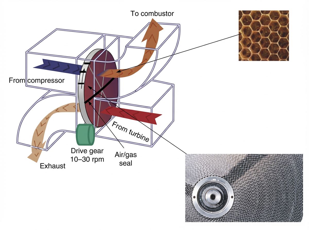
Common in gas turbines, combined-cycle power plants, and large HVAC systems, this design features a porous wheel—sometimes as large as a garage door—that spins slowly, typically at a leisurely 1–3 rpm. Half the wheel sits in the hot exhaust stream, soaking up heat; the other half sits in the cold intake stream, surrendering that heat. As the wheel turns, it continuously carries thermal energy from the hot side to the cold side like a conveyor belt of heat.
The Advantage: It is remarkably compact for its heat-transfer capacity and provides continuous, uninterrupted energy recovery. No dramatic valve switching, no waiting for cycles—just smooth, perpetual motion.
The Drawback: Sealing is a persistent engineering headache. Because the wheel is always moving, maintaining a perfect seal between the hot and cold sides is nearly impossible. Gas inevitably leaks between streams, and a small amount of exhaust contamination is unavoidable. For power plants, this is acceptable. For food processing or pharmaceutical clean rooms, it’s a dealbreaker
2. The Fixed-Bed Regenerator
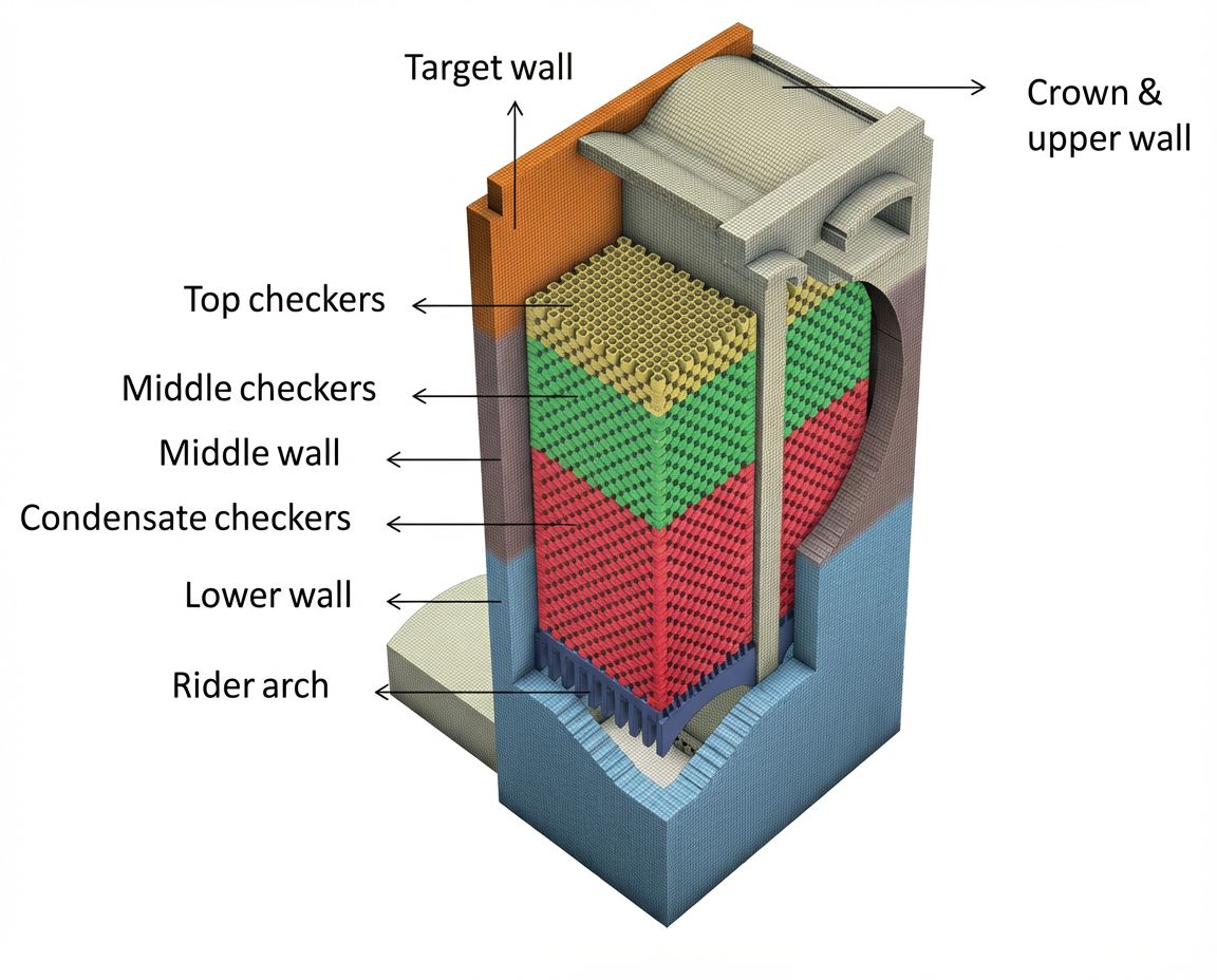
These are the true giants of the regenerator world, architectural monuments to heat recovery often found in glass manufacturing plants and integrated steel mills. They consist of two enormous stationary chambers—sometimes the size of multistory buildings—filled with thousands of tons of checker-patterned refractory bricks stacked in intricate lattices that maximize surface area.
The system operates on alternating cycles controlled by massive valves: while Chamber A absorbs heat from roaring exhaust gases (often laden with dust, soot, and chemical vapors), Chamber B releases its stored heat to fresh combustion air. Every 15 to 30 minutes, the valves flip with industrial precision, reversing the flow. Walk past one of these installations during the switch, and you can hear the deep, resonant boom of valve gates slamming shut—the breath of industrial giants.
The Advantage: No moving internal parts means they can be built to colossal scales and handle filthy, ash-choked, chemically aggressive exhaust without jamming, corroding, or requiring constant maintenance. They are brutally simple and incredibly durable—some have operated continuously for decades.
The Drawback: They require expensive, complex valve systems (often several meters in diameter) to manage the periodic airflow switching. These valves themselves become wear points, and the alternating thermal cycles can stress the brickwork over time, requiring periodic rebuilding.
Materials: Surviving the Inferno
The choice of material for the matrix isn’t just engineering preference—it’s survival. Pick the wrong material, and your regenerator becomes a very expensive pile of slag.
Stainless Steel and Aluminum: Used for temperatures up to 870°C, metallic matrices are common in HVAC “energy recovery wheels” that recycle heat (and sometimes moisture) from building exhaust to keep office air comfortable without wasting energy. These wheels often look like oversized honeycomb structures, their thin metal corrugations designed to maximize surface area while minimizing weight.
Ceramics: The heavyweights. Essential for glass furnaces operating at 1400-1600°C and steel mill blast furnaces pushing past 1000°C, ceramic matrices can withstand punishing temperatures that would vaporize most metals. The bricks—often made from magnesia, alumina, or silica compounds—are stacked in checkerboard patterns with deliberate gaps, creating a labyrinth of channels that force hot gases to tumble and swirl, maximizing heat transfer. While they are brittle and prone to cracking under rapid thermal shock (imagine pouring ice water on a red-hot brick), they are immune to the chemical corrosion and oxidation that devour metals at high temperatures.
Some advanced systems even use hybrid approaches: metal matrices for the cooler sections nearest the exit, transitioning to ceramics in the hottest zones.
The Engineering Balancing Act
Designing these systems is a rigorous exercise in thermodynamics, fluid mechanics, and materials science. Engineers scrutinize specific metrics to ensure the system delivers real value and doesn’t just look good on paper.
Effectiveness (ε)
This is the “grade” given to the regenerator, the report card of thermal performance. It represents the ratio of actual heat recovered to the maximum theoretically possible heat transfer. A high-performing regenerator might achieve an effectiveness of 90%, meaning the cold air exits the system nearly as hot as the exhaust gas entered. Achieving that final 5-10% of effectiveness, however, often requires doubling the size and cost of the matrix—a classic case of diminishing returns.
The Capacity Ratio (Cr*)
To stabilize temperatures and maintain consistent performance, the matrix must have a high heat capacity relative to the fluid flowing through it. Think of it as thermal inertia. If the matrix is too light or has too little mass, it heats and cools too rapidly, causing wild temperature swings. If it’s too heavy, it takes forever to reach operating temperature and responds sluggishly to changes in flow. Engineers aim for a “Goldilocks zone” where the matrix mass is just right—typically achieved by calculating the ratio of matrix thermal capacity to gas stream thermal capacity.
The Leakage Trade-off
Regenerators have a unique Achilles’ heel that recuperators don’t share: carryover and cross-contamination. Because the same matrix physically contacts both dirty exhaust and fresh intake air, a small amount of fluid inevitably gets trapped in the porous channels and mixes into the other stream when flows reverse.
In rotary designs, this happens continuously as pockets of gas rotate from one side to the other. In fixed-bed systems, it happens during the switching period—that brief moment when residual exhaust still lurks in the hot matrix before fresh air sweeps through.
For most industrial applications (power generation, metallurgy, glass making), this 1-5% contamination is tolerable or even negligible. But this is precisely why regenerators are rarely used where strict purity is required—hospital breathing air systems, semiconductor fabrication clean rooms, or food-grade processes—unless complex intermediate purge loops or additional filtration systems are installed, which often defeats the economic advantage.
Real-World Impact: Turning Waste into Wealth
The numbers behind regenerator efficiency aren’t just impressive—they’re transformative. A large glass manufacturing plant using regenerators can reduce fuel consumption by 30-40% compared to direct-fired systems. In an industry that operates furnaces 24/7 for years at a time (glass furnaces can’t be shut down without catastrophic damage), this translates to millions of dollars in annual savings and massive reductions in carbon emissions.
Similarly, in steel production, Cowper stoves—massive fixed-bed regenerators used to preheat blast furnace air—have been standard technology for over a century precisely because the economics are irrefutable. These cathedral-sized structures, often standing 30-40 meters tall, recover waste heat that would otherwise escape into the sky, feeding it back into the process to sustain temperatures exceeding 2000°C needed to smelt iron ore.
Summary
Regenerators are the unsung heroes of industrial energy conservation, the silent accountants of the thermal economy. Whether they are ceramic giants recovering waste heat in a steel mill or spinning metal wheels trimming kilowatts from a skyscraper’s energy bill, they perform the same fundamental magic: turning waste into value.
By mastering the ancient rhythm of storage and release—breathe in, hold, breathe out—they allow industries to burn less fuel, emit fewer pollutants, and push the boundaries of achievable temperature. In a world increasingly concerned with energy efficiency and carbon footprints, these thermal batteries quietly save more energy every day than many celebrated “green technologies.”
They don’t generate headlines, but they do generate results—one hot breath at a time.

FAQ
Q1: What's the main difference between a regenerator and a recuperator?
A recuperator (like a car radiator) continuously transfers heat through a metal wall separating hot and cold streams. A regenerator uses a porous solid matrix that alternates between absorbing heat from hot exhaust and releasing it to cold intake air—it's a "thermal battery" that stores and releases heat in cycles rather than transferring it continuously.
Q2: Why aren't regenerators used in hospitals or food processing plants?
Regenerators have an inherent contamination issue: the same matrix contacts both dirty exhaust and fresh intake air, causing 1-5% cross-contamination. In rotary designs, gas pockets rotate between streams; in fixed-bed systems, residual exhaust remains during flow switching. This is acceptable for steel mills and glass furnaces but unacceptable where air purity is critical, unless expensive additional filtration is added.
Q3: How much energy can regenerators actually save?
Regenerators typically achieve 85-95% thermal efficiency. A large glass plant can cut fuel consumption by 30-40%, saving millions annually. In steel production, Cowper stoves (massive regenerators) have been standard for over a century because they recover waste heat to sustain 2000°C+ temperatures—turning what would escape as waste into productive energy that reduces both costs and emissions.
Keep Learning
How Transparent Graphene Heaters Clear Fogged Glass
Key Takeaways Atom-thin transparency: A single graphene layer transmits about 97.7% of visible light, while five stacked layers still pass roughly 87.3%, making the heater nearly invisible on glass or plastic. Fast, controllable heating: A monolayer device reaches its target temperature with a thermal time constant of only about 6–7 seconds, and input power can be adjusted to hold temperatures from 38 °C up to around 80 °C. Efficiency advantage: Graphene heaters achieved higher temperatures at the sam......
Process Control, Monitoring, and Quality Assurance in Induction Heating: Reducing Risk Without Cutting Every Part
Key Takeaways Separate control from monitoring: A control system executes the recipe; a monitoring system independently verifies what actually happened. Independence turns logs into evidence. Monitor intermediate variables: You can't measure fatigue strength inline, but you can measure delivered kW, frequency stability, position, and quench variables—then compare each cycle to a validated "good envelope." Signature monitoring beats single thresholds: Time-series signatures capture ramps, holds, and tr......
Cooling Induction Power Supplies: Designing the Thermal System That Protects Your Electrical System
Key Takeaways Cooling is a first-class subsystem: Many "electrical" failures in induction lines are actually thermal problems—drifting water temperature, clogged filters, or unbalanced branch flow. Measure at the branch, not the header: A healthy header can mask a starved branch. Branch flow to the highest-loss modules is the single most useful cooling measurement. Trend cooling like a process variable: Baseline flow, temperature, and filter pressure drop during commissioning, then trend them to turn ......
Independent Frequency and Power Control in Induction Inverters: Turning Frequency Back Into a Process Variable
Key Takeaways Frequency as a process variable: Independent frequency and power control decouples resonance supervision from kW regulation, letting engineers set frequency based on process physics rather than control mechanics. Measurable validation: Prove independent control with three commissioning tests—fixed-frequency power steps, fixed-kW frequency sweeps, and coupling variation stability. Production consistency: Stable frequency improves recipe portability, reduces hidden process changes, and mak......
Simultaneous Dual-Frequency Induction Heating: When One Frequency Forces the Wrong Compromise
Key Takeaways One frequency, one compromise: When geometry demands both deep bulk heating and controlled surface gradients simultaneously, a single frequency forces an unacceptable trade-off—dual-frequency widens the process window. Give each channel a role: Assign the lower frequency to bulk penetration and the higher frequency to surface shaping. Structured recipe development follows naturally from this separation. Validate with metrics, not opinions: Dual-frequency is justified only when controlled......
Power Supplies by Application Family: Joining, Mass Heating, and Strip Processing
Key Takeaways Joining operations (brazing, soldering, bonding) demand higher frequencies and matching flexibility to handle variable coil coupling and precision surface heating. Mass heating lines (billets, bars, slabs) prioritize continuous duty, efficiency, and ruggedness at high power levels with multi-coil zone control. Strip processing requires architectures that separate control electronics from high-frequency inverter modules to cope with harsh installation environments. Specifying only kW and ......