
The Blood and Breath of Industry: Mastering the Physics of Heat Exchangers
12 min
- 1. The Great Energy Ledger: Conservation Above All
- 2. The Obstacle Course: Understanding the U-Value
- 3. The Driving Force: LMTD and Flow Architecture
- 4. The Turbulence Trade-off: No Free Lunch
- 5. Phase Change: The Turbo Boost
- 6. Practical Wisdom: Myths and Misconceptions
- Summary: The Art and Science of Thermal Design
- FAQ
If the mechanical structure—the shell, the plates, the frame—represents the “bones” of a heat exchanger, then thermohydraulics is its blood and breath. It is the invisible force that determines whether your industrial process hums along efficiently or gasps for performance.
In the complex world of thermal engineering, it is easy to get lost in differential equations and computational fluid dynamics. However, the best designs don’t emerge from pure mathematics alone. They rely on physical intuition: a deep understanding of how energy moves (thermodynamics) and the cost of moving that energy (hydraulics). By stripping away the complex math and focusing on first principles, we can uncover the operational logic that keeps industrial processes running—from the air conditioner in your car to the massive condensers in power plants.
1. The Great Energy Ledger: Conservation Above All
At its core, a heat exchanger is simply an energy transfer station, a middleman in the world of thermal processes. It operates on two immutable laws of the universe: Energy is never destroyed (only transformed), and heat always flows from hot to cold, never the reverse—at least not without doing work, as your refrigerator demonstrates every day.
Before any complex design begins, before a single tube is sized or a single plate is stamped, engineers perform a simple “forensic accounting” check using the macro energy balance. Assuming no external heat loss to the environment (a reasonable assumption for well-insulated industrial equipment), the energy given up by the hot fluid must exactly match the energy absorbed by the cold fluid:

Here,  represents mass flow rate (how much fluid passes through per second),
  is the specific heat capacity (how much energy it takes to warm the fluid), and the temperature differences tell us the thermal journey each fluid makes.
If this equation doesn’t balance—if the numbers refuse to meet in the middle—the design is thermodynamically impossible. No amount of clever engineering can violate conservation of energy. It is the first gate of verification, the bouncer at the door of feasibility.
Consider a real example: You want to cool 10 kg/s of oil from 150°C to 70°C using water that enters at 20°C. The energy balance immediately tells you the minimum water flow rate needed and its exit temperature. Miss this step, and you might design a beautiful heat exchanger that simply cannot do the job.
2. The Obstacle Course: Understanding the U-Value
How “fit” is your heat exchanger? How easily can it move heat from one fluid to another? This athletic ability is defined by the Overall Heat Transfer Coefficient (U), measured in watts per square meter per degree Kelvin (W/m²·K).
Imagine heat as a runner trying to jump from a hot fluid inside a tube to a cold fluid outside it. It isn’t a single graceful leap; it’s a grueling obstacle course with multiple hurdles:
First hurdle: The heat must convect through the turbulent or laminar boundary layer of the hot fluid to reach the tube wall. This is like swimming through molasses of varying thickness.
Second hurdle: It encounters dirt, scale, or biofilm—the inevitable fouling that accumulates during operation. This acts like a thick winter coat, dramatically insulating the surface.
Third hurdle: The heat must conduct through the metal tube wall itself. Copper sprints through this stage; stainless steel takes its time.
Fourth hurdle: Finally, it must convect through the cold fluid’s boundary layer on the other side.
Mathematically, we treat these obstacles as a series of thermal resistances, much like electrical resistances in a circuit:
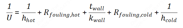
To improve the U-value—to make heat transfer easier—we must lower these barriers. But here’s where engineering judgment enters:
Fluid Properties: Water conducts heat significantly better than oil, which is why water-to-water exchangers naturally achieve U-values of 2,000-4,000 W/m²·K, while oil-to-oil units struggle to reach 200-400 W/m²·K. You cannot change the fundamental physics of your process fluids, but you can design around their limitations.
The “Winter Coat” (Fouling): Over time, dirt and scale build up on surfaces like plaque in an artery. In cooling tower water systems, calcium carbonate can deposit at alarming rates. In refineries, crude oil leaves behind asphaltenes and waxes. This fouling acts like thermal insulation, and there’s no way to completely prevent it in real industrial service. Smart engineers design with a safety margin—surplus area, typically 15-30%—to account for this inevitable degradation. The exchanger starts oversized so that even when dirty, it can still meet the duty.
3. The Driving Force: LMTD and Flow Architecture
Temperature difference (ΔT) is the engine of heat transfer, the pressure gradient that pushes energy across the barrier. No temperature difference means no driving force, no matter how large your heat exchanger. However, because fluids change temperature as they travel through the unit, we cannot use a simple arithmetic average. The temperature difference is high at one end and low at the other.
Engineers use the Logarithmic Mean Temperature Difference (LMTD) to capture the true effective driving force across the entire length of the exchanger. It weights the temperature profile correctly, accounting for the exponential nature of heat transfer.
But here’s the key insight: The way we arrange the flow paths—the architecture of our design—determines how powerful this driving force can be.
The Duel: Counterflow vs. Parallel Flow
Counterflow: Fluids move in opposite directions, like two trains passing on adjacent tracks going opposite ways. The hottest hot fluid meets the warmest cold fluid at one end; the coolest hot fluid meets the coldest cold fluid at the other. This maintains a relatively high and uniform ΔT throughout the unit, making counterflow the gold standard for thermal efficiency. In some cases, the cold fluid can even exit hotter than the hot fluid enters—an impossible feat in parallel flow.
Parallel Flow: Fluids travel side-by-side in the same direction. The driving force is enormous at the start where maximum temperature difference exists, but it collapses rapidly as both fluids approach equilibrium near the outlet. While thermally less efficient, parallel flow has a secret weapon: temperature control. When you need to prevent thermal shock, freezing, or localized boiling at the inlet, parallel flow moderates the wall temperature immediately by mixing the thermal profiles.
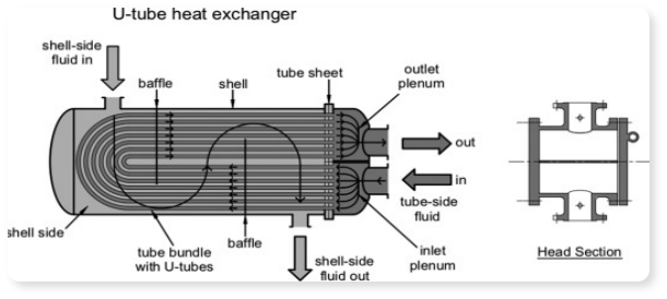
In multi-pass shell-and-tube exchangers, we often use a hybrid approach—not pure counterflow, not pure parallel, but something in between—optimized with a correction factor to account for the reality of multiple flow paths.
4. The Turbulence Trade-off: No Free Lunch
Thermodynamics teaches us the universe’s fundamental rule: you cannot get something for nothing. In heat exchanger design, the currency we spend is Pressure Drop (ΔP), and the commodity we buy is heat transfer performance.
To get heat from the bulk fluid into the wall, we need to move the fluid, and how it moves matters enormously. There are two main flow regimes:
Laminar Flow (Layered Sliding): Think of a calm river or honey sliding down a tilted plate. The fluid moves in smooth, parallel layers with no mixing between them. Heat has to slowly diffuse through these layers via molecular conduction to reach the wall—a painfully slow process. Laminar flow is energy-efficient (low pumping cost, minimal pressure drop) but thermally lazy. Heat transfer coefficients are poor.
Turbulent Flow (Chaotic Mixing): If we push the fluid faster past a critical velocity (characterized by the Reynolds number exceeding approximately 2,300 in pipes), the flow destabilizes. It begins to mix violently with swirling eddies and vortices. This “stirring” action constantly brings fresh, hot fluid into intimate contact with the wall, dramatically improving heat transfer—often by a factor of 10 or more compared to laminar conditions.
The Engineer’s Dilemma
Turbulence is highly desirable for heat transfer performance, but it creates friction—lots of it. Friction means pressure drop. Pressure drop means pumping power. Pumping power means operating cost, year after year.
Here’s the optimization problem: If you don’t use your allowed pressure drop budget to generate turbulence, your heat exchanger will need enormous surface area to compensate, making it huge and expensive to build. If you use too much pressure drop, your capital cost might be reasonable, but your operating costs (electricity for pumps) will skyrocket, and you might even cause vibration or erosion problems.
The goal is to spend your pressure drop wisely. Most industrial designs aim for 0.5-2 bar (7-30 psi) of pressure drop as a reasonable compromise. Refineries might tolerate more; pharmaceutical plants with expensive, shear-sensitive fluids might allow much less.
5. Phase Change: The Turbo Boost
When fluids boil or condense, the rules of the game change dramatically. During phase change, fluids absorb or release massive amounts of latent heat without changing temperature—the energy goes entirely into breaking or forming molecular bonds rather than increasing kinetic energy.
Consider water at atmospheric pressure: raising its temperature from 99°C to 100°C as liquid requires 4.2 kJ per kilogram. But converting that 100°C liquid into 100°C steam requires 2,257 kJ per kilogram—over 500 times more energy, with zero temperature change. This is why steam heating is so effective and why condensers can be relatively compact.
Because of the intense molecular activity during phase change—bubbles forming and collapsing in boiling, droplets forming in condensation—heat transfer coefficients can be an order of magnitude higher than simple single-phase liquid cooling. Boiling water can achieve 10,000-100,000 W/m²·K compared to 500-10,000 W/m²·K for turbulent water flow.
In these scenarios, the complex interaction of flow configurations matters less than ensuring you have sufficient surface area for the phase change to occur and managing the two-phase flow patterns to prevent operational issues like flow instability or liquid carryover.
6. Practical Wisdom: Myths and Misconceptions
To wrap up, let’s address common pitfalls in design logic that trip up even experienced engineers.
“More plates is always better.”
False, and dangerously so. If you add plates to a plate heat exchanger without increasing the total flow rate, the flow distributes among more channels. The fluid velocity in each individual channel drops proportionally. You might accidentally shift the flow regime from turbulent to laminar, causing a catastrophic drop in the heat transfer coefficient that completely outweighs the benefit of the extra surface area. Your bigger exchanger performs worse. Always check the Reynolds number.
“We should always aim for the highest U-value possible.”
Risky thinking. Chasing an extremely high U often requires dangerous velocities (causing vibration, noise, and erosion), or it demands tiny channels that clog easily with debris or foulants. A U-value of 3,000 W/m²·K that you can sustain for five years beats a U-value of 5,000 W/m²·K that drops to 1,000 W/m²·K after six months of fouling. A good design balances efficiency with maintenance reality and long-term reliability.
“Counterflow is always the right choice.”
Mostly true, but not universally. If you need to cool a very hot liquid quickly without overheating or thermally stressing the wall material (perhaps you’re using a polymer liner or have concerns about thermal expansion), parallel flow mixes the temperatures immediately at the inlet. This provides a safer, more moderate wall temperature profile, even though you sacrifice some overall efficiency. Sometimes safety trumps optimization.
“Bigger is better—oversize it to be safe.”
Tempting but flawed. An oversized heat exchanger might seem conservative, but if it’s too large, the fluid velocity drops below the minimum required for turbulence or self-cleaning. The unit fouls rapidly, performs poorly, and ironically becomes less reliable than a properly sized design. Goldilocks was right: not too big, not too small, but just right.
Summary: The Art and Science of Thermal Design
Heat exchanger design is not just about drawing tubes and shells on a CAD program; it is a high-wire balancing act between thermal efficiency, hydraulic cost, mechanical longevity, and economic reality. The best designs respect all these constraints simultaneously.
By mastering the “blood and breath” of thermohydraulics—understanding how energy moves and what it costs to move it—we move from simply operating equipment to truly understanding the pulse of the plant. We can diagnose problems from pressure gauge readings, predict fouling from temperature trends, and optimize processes that seemed already optimized.
The heat exchanger, humble and often hidden in the industrial landscape, is far more than a box of tubes. It is a carefully orchestrated thermal dance, a negotiation between the laws of physics and the constraints of economics, engineered by those who understand both the science and the art of heat transfer.

FAQ
FAQ 1: Why does my heat exchanger perform worse over time even though it's properly maintained?
Answer: This is due to fouling—the buildup of dirt, scale, or biofilm on internal surfaces. These deposits act like an insulating layer, increasing thermal resistance and reducing the overall heat transfer coefficient (U-value). Smart designers account for this by including a 15-30% oversizing margin during initial design. To combat fouling, regular cleaning schedules and periodic inspections of temperature performance are essential.
FAQ 2: Should I always choose counterflow design for maximum efficiency?
Answer: Counterflow is generally the most thermally efficient because it maintains a high temperature difference throughout the exchanger. However, it's not always the best choice. If you need to protect sensitive materials from thermal shock, prevent localized boiling, or avoid overheating the wall, parallel flow may be safer despite lower efficiency. The best design balances thermal performance with operational safety and long-term reliability.
FAQ 3: Why is turbulent flow important, and what's the catch?
Answer: Turbulent flow dramatically improves heat transfer—often 10 times better than laminar flow—because it creates mixing and constantly brings fresh fluid to the wall. The tradeoff is pressure drop, which requires pumping power and increases operating costs. Most industrial designs target 0.5-2 bar of pressure drop as a reasonable compromise between capital investment and long-term energy expenses.
Keep Learning
Simultaneous Dual-Frequency Induction Heating: When One Frequency Forces the Wrong Compromise
Key Takeaways One frequency, one compromise: When geometry demands both deep bulk heating and controlled surface gradients simultaneously, a single frequency forces an unacceptable trade-off—dual-frequency widens the process window. Give each channel a role: Assign the lower frequency to bulk penetration and the higher frequency to surface shaping. Structured recipe development follows naturally from this separation. Validate with metrics, not opinions: Dual-frequency is justified only when controlled......
Power Supplies by Application Family: Joining, Mass Heating, and Strip Processing
Key Takeaways Joining operations (brazing, soldering, bonding) demand higher frequencies and matching flexibility to handle variable coil coupling and precision surface heating. Mass heating lines (billets, bars, slabs) prioritize continuous duty, efficiency, and ruggedness at high power levels with multi-coil zone control. Strip processing requires architectures that separate control electronics from high-frequency inverter modules to cope with harsh installation environments. Specifying only kW and ......
Simultaneous Dual-Frequency Induction Power: When One Frequency Forces the Wrong Compromise
Key Takeaways Dual-frequency is justified by robustness, not complexity: It should only be adopted when a single frequency forces an unacceptable compromise between surface and bulk heating requirements. Give each frequency a defined role: Assign the lower frequency to bulk heating/penetration and the higher frequency to surface shaping—then develop recipes one variable at a time. The combining network is the engineering center of gravity: Frequency-selective coupling paths, thermal rating for worst-c......
Applying Induction Power Supplies in the Real World: Constraints That Decide Uptime and Quality
Key Takeaways Application constraints dominate real-world performance: Two induction systems with identical kW ratings can behave very differently depending on cable length, cooling water temperature, dust levels, and fixture repeatability. Design for drift, not for perfect day one: Coils deform, filters clog, sensors drift, and connectors loosen under thermal cycling. Baseline monitoring during commissioning is essential. Mechanical repeatability often beats control complexity: Improving fixturing an......
Medium- and High-Frequency Transformers in Induction Systems: Design Drivers Engineers Should Actually Care About
Key Takeaways Not Passive: Transformers set the electrical operating point for the entire induction station—coil voltage, current, capacitor stress, and inverter margin all depend on transformer choice. Frequency Effects: At higher frequencies, winding losses and stray capacitance dominate; a transformer that looks fine on turns ratio can fail a duty-cycle test if loss distribution is wrong. Placement Matters: Moving the transformer and capacitor bank closer to the coil reduces high-frequency loop len......
Load Matching in Induction Heating: Designing for Stability, Efficiency, and Real-World Variation
Key Takeaways Dynamic Load: Induction heating loads are not fixed—coupling, material properties, and temperature all shift impedance during operation, making matching a continuous design challenge. Q Factor Matters: High-Q loads can produce large circulating currents and capacitor stress even at modest delivered kW; design for the worst-case kVA, not just power. Discrete Ranges Win: Transformer taps and capacitor steps that cover discrete matching ranges outperform a single broad-range configuration f......