The Hidden Science of Industrial Giants: Why Material Selection Makes or Breaks a Heat Exchanger
9 min
- The Stakes Are Real
- Know Your Enemy
- The Steel Menagerie
- The Core: Tubes and Tubesheets
- The Alchemy of Welding
- The Final Exam
- FAQ
Walk through a petrochemical plant and you'll notice them almost immediately — hulking cylinders of steel, wrapped in insulation and threaded with pipes, hissing quietly amid the industrial roar. To the untrained eye, they look like glorified plumbing. But to a process engineer, the heat exchanger is something closer to a miracle of applied science: a machine that shuffles vast quantities of thermal energy between fluids without ever letting those fluids touch, doing so reliably, hour after hour, year after year, in conditions that would reduce most materials to rubble.
The reason some of these machines run for thirty years without incident — and others fail catastrophically — often comes down to decisions made before a single bolt is tightened. It comes down to material selection and fabrication. Get it right, and you have a workhorse. Get it wrong, and you have a bomb.
The Stakes Are Real
This is not hyperbole. In 1989, the Pasadena refinery explosion — triggered in part by equipment failure — killed 23 workers and injured hundreds more. Material failure in high-pressure, high-temperature environments doesn't just mean downtime; it can mean catastrophe. A single corroded tube can leak a flammable or toxic fluid into a process stream at hundreds of degrees Celsius. The results are not abstract.
Engineers who design heat exchangers are acutely aware of this. Their goal is what the industry calls the "Perfect Trinity": strict compliance with ASME (American Society of Mechanical Engineers) safety codes, robust resistance to corrosion, and an optimized Total Cost of Ownership over the machine's lifetime. Achieving all three simultaneously is the central challenge of the discipline — and it begins with a deep understanding of the environment the machine will inhabit.
Know Your Enemy
Before an engineer picks up a materials handbook, they conduct what amounts to a forensic investigation of the future. What fluids will flow through this machine? At what temperatures and pressures? Are there "upset conditions" — sudden spikes that might push the system beyond its normal operating range? What happens when those conditions occur?
Corrosion is the primary villain in this story, and it is deceptive. It does not announce itself dramatically; it works slowly, invisibly, from the inside out. Some fluids are obviously aggressive — concentrated acids, chlorinated compounds, hydrogen-rich streams at high temperature. Others are subtler. Even water, depending on its oxygen content and pH, can silently hollow out a carbon steel tube over a period of years.
The environmental audit also considers mechanical hazards: vibration from fluid flow, thermal cycling as the machine heats up and cools down repeatedly, and the long-term phenomenon known as creep — the slow, irreversible deformation that metals undergo when held under stress at high temperatures. A material that handles stress beautifully at room temperature may quietly stretch and distort at 450°C.
The Steel Menagerie
Not all steels are created equal. The industrial world deploys a small family of alloys, each with distinct strengths and weaknesses.
Carbon steel is the reliable workhorse — cheap, strong, and widely available. It handles water and steam competently. But it corrodes readily in more aggressive environments, making it a poor choice for anything more chemically demanding.
Low-alloy steels add small amounts of nickel, chromium, or molybdenum to the iron-carbon base. These additions — sometimes just a fraction of a percent — dramatically improve toughness and resistance to corrosion. The tradeoff is cost and, sometimes, weldability.
Chrome-moly (Cr-Mo) steels are the specialists of the group, engineered for environments like hydrogen crackers — refinery units where hydrogen gas at extreme temperatures and pressures would cause ordinary steel to absorb hydrogen atoms and become brittle. Cr-Mo resists this "hydrogen embrittlement," but it demands careful handling: welding it incorrectly can introduce new failure modes, and aging at high temperatures can gradually alter its microstructure in ways that engineers must specifically test for.
The Core: Tubes and Tubesheets
Inside a shell-and-tube heat exchanger — the most common industrial design — thousands of thin-walled tubes carry one fluid while the other bathes them from the outside. The tube bundle is simultaneously the machine's most critical and most vulnerable component. Its walls may be only a millimeter or two thick, yet they bear the full burden of separating fluids at pressure while conducting heat efficiently.
Where the tubes meet the main body of the exchanger, they are anchored in massive plates of metal called tubesheets. These must have a perfectly uniform internal grain structure — the microscopic crystalline architecture of the metal — or the joints between tube and plate become sites of hidden weakness, prone to slow leaks.
Engineers argue about tube manufacture the way audiophiles argue about speaker wire. Seamless tubes — formed by extruding solid metal into a hollow cylinder — have no longitudinal weld seam and are considered more reliable. Welded tubes, formed by rolling flat strip and fusing the edges, are cheaper and often perfectly adequate. The choice depends on the severity of the service and the risk tolerance of the operator.
A subtler danger lurks in the fabrication shop: contamination. If a stainless steel tube is handled with ordinary carbon steel tools — lifted with a steel hook, brushed with a steel wire brush — microscopic iron particles embed themselves in the surface. In the presence of moisture, those particles corrode rapidly, leaving pits in the stainless steel below. In the workshop, cleanliness is not a preference. It is engineering practice.
The Alchemy of Welding
If material selection is the brain of fabrication, welding is its nervous system — the process that holds everything together, and the process most likely to introduce catastrophic hidden flaws.
Welding subjects metal to an extraordinary thermal insult. The local temperature at the weld pool may reach 1,500°C or more, then plunge back toward ambient in a matter of seconds. This rapid heating and cooling — repeated dozens or hundreds of times across a fabrication job — reshapes the metal's microstructure in ways that can either strengthen it or leave it fragile.
Two failure modes haunt welders particularly. The first is hydrogen-induced cracking, sometimes called "cold cracking" because it develops after the weld has cooled. Hydrogen gas, absorbed into the weld pool from moisture in the electrode coating or the surrounding atmosphere, becomes trapped as the metal solidifies. Under residual stress, this trapped hydrogen exerts enormous internal pressure, forcing microscopic cracks through the hardened steel. The fix is unglamorous but effective: use low-hydrogen electrodes, store them in heated ovens to prevent moisture absorption, and preheat the base metal before welding so that hydrogen can diffuse away harmlessly before the metal locks it in.
The second threat is hot cracking, which occurs while the metal is still solidifying. Trace impurities — sulfur and phosphorus in particular — have lower melting points than the surrounding steel. As the pure metal crystallizes, it pushes these liquid impurities toward the center of the weld bead. There they sit, a thin film of molten contamination, until the contracting solid tears them apart. The defense is tight control of steel composition at the mill level, paired with welding techniques that control the bead shape and minimize the region where impurities concentrate.
The Final Exam
No heat exchanger leaves a fabrication shop on trust. Before it ships, it faces a methodical battery of quality assurance tests designed to catch every flaw that chemistry, skill, and careful process might have missed.
Every plate and pipe arrives with a Mill Test Certificate — a kind of birth certificate that records its exact chemical composition and mechanical properties. These documents are checked and filed. Traceability matters: if a flaw is discovered in service, investigators need to be able to trace it back to a specific batch of raw material.
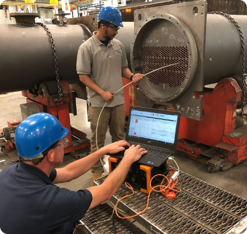
Welds are inspected using nondestructive testing techniques that see inside the metal without damaging it. Radiography — essentially an industrial X-ray — reveals voids, inclusions, and cracks invisible to the eye. Ultrasonic testing sends sound waves through the metal and analyzes the echoes, detecting flaws that X-rays might miss. For surface cracks, magnetic particle inspection and dye penetrant methods expose defects at the microscopic level.
Finally, the assembled vessel undergoes a hydrotest: it is filled with water and pressurized to 130–150% of its design operating limit. Water is used rather than gas because water, being incompressible, releases very little energy if a vessel ruptures. The hydrotest is the machine's final examination — and it is pass or fail.
All of this documentation — the material certificates, weld records, inspection reports, and test results — is compiled into a Data Book. This thick dossier follows the vessel through its entire operational life. It is the machine's biography and its safety record, proof that from the atomic structure of the alloy to the final coat of protective paint, nothing was left to chance.
In a world of complex machinery, heat exchangers rarely make headlines. They just do their work quietly, year after year, in conditions that would destroy lesser equipment. That quiet reliability isn't accidental. It is the product of science, rigor, and a relentless respect for what happens when things go wrong.

FAQ
Q: Why is material selection so critical for heat exchangers?
A: Material selection directly impacts safety and longevity. Heat exchangers operate under extreme conditions—high temperatures, pressures, and corrosive fluids. The wrong material can lead to catastrophic failures like the 1989 Pasadena refinery explosion that killed 23 workers. Engineers must balance ASME safety compliance, corrosion resistance, and total cost of ownership. A well-chosen material means decades of reliable operation; a poor choice can mean disaster.
Q: What makes welding such a vulnerable point in heat exchanger fabrication?
A: Welding subjects metal to extreme thermal stress—temperatures reaching 1,500°C followed by rapid cooling—which can create hidden flaws. Two main threats are hydrogen-induced cracking (from moisture trapped in cooling metal) and hot cracking (from impurities like sulfur concentrating as metal solidifies). Even minor contamination from using carbon steel tools on stainless steel can cause corrosion. That's why proper welding technique, material handling, and rigorous inspection are essential.
Q: How do manufacturers ensure a heat exchanger is safe before it enters service?
A: Every heat exchanger undergoes extensive quality assurance testing. This includes verifying Mill Test Certificates for material traceability, nondestructive testing like X-rays and ultrasonic inspection to detect internal flaws, and a final hydrotest where the vessel is pressurized to 130-150% of its design limit using water. All documentation is compiled into a Data Book that follows the equipment throughout its operational life, ensuring complete accountability from raw material to final assembly.
Keep Learning
Induction Billet Heating: How to Achieve Uniform Heating
Induction billet heating prepares metal for forging, extrusion, or rolling by generating heat inside the workpiece. For steel billets, reaching the required exit temperature is only part of the task: the temperature distribution from surface to core and along the billet must also suit the forming process. Uniformity depends on how frequency, coil geometry, heat transfer, power distribution, and billet movement work together. This guide focuses on through-heating steel billets, particularly in progress......
How to Upgrade a 3D Printer Heated Bed with a Silicone Heater
If your 3D printer heated bed takes too long to reach temperature, develops uneven heating, or struggles to maintain a stable surface temperature, a silicone heater can be a practical upgrade. Faster warm-up and more uniform heat can improve first-layer consistency and reduce temperature-related printing issues. This guide explains how to identify when a heated-bed upgrade is needed, choose a suitable silicone heater, install it safely, and verify the results. Quick Answer A silicone heater can be a s......
How Graphene and MXene Flake Sensors Detect Force
Key Takeaways Flake networks sense force through microstructural change: Graphene and MXene coatings distribute conduction across overlapping platelets whose contacts shift under stretch or pressure, producing measurable resistance changes. Three mechanisms compete: Crack propagation, flake slippage, and quantum tunnelling each dominate at different deformation levels, giving many sensors multiple sensitivity regions rather than one uniform response. The substrate is an active partner: Elastomers, tex......
Conductive 2D Coatings Are a Matching Problem, Not a Miracle Ink
Key Takeaways Ink is a system, not a material: Conductivity depends on the combined effect of flake chemistry, solvent, additives, substrate, coating method, and post-processing—not on the 2D filler alone. Three carbon routes carry different trade-offs: GNPs demand dispersion engineering, GO shifts effort to a reduction step, and MXenes move the bottleneck to synthesis, storage, and oxidation control. Substrate geometry drives method selection: Spray and blade coating suit flat sheets; dip coating nat......
Graphene Heat Spreader Design: Layers and Interfaces
Key Takeaways Conductivity alone is not enough: A record thermal-conductivity value does not guarantee a cooler chip. Effective thickness, interface resistance, hot-spot geometry, and heat-sink connections all belong to the same thermal path. Few-layer graphene can outperform a single layer in practice: A few-layer sheet provides a larger heat-flow cross section and better tolerates transfer, embedding, and defects, even though its intrinsic conductivity is lower. Interface resistance is the bottlenec......
How Graphene Heat Spreaders Cool SOI Chip Hot Spots
Key Takeaways Buried oxide is a thermal bottleneck: SOI's insulating layer improves electrical isolation but traps heat near transistor channels, creating dangerous hot spots that package-level cooling alone cannot fix. Graphene enables lateral heat routing: Placing graphene or few-layer graphene beneath the buried oxide adds a high-conductivity sideways path, redistributing hot-spot energy toward dedicated sinks without removing any heat itself. Multi-source chips benefit most: Finite-element modelin......