
The Silent Killer in the Shell: Understanding Flow-Induced Vibration
19 min
- What Exactly Is Flow-Induced Vibration?
- The Four Mechanisms: How Physics Shakes the Tubes
- The Danger Zones: Where Failures Happen
- Diagnosis and Prevention: Engineering the Solution
- The Complexity of Two-Phase Flow: When Things Get Weird
- Closing Thoughts: Respecting the Silent Killer
- FAQ
On November 7, 1940, the Tacoma Narrows Bridge twisted and writhed in a 40-mile-per-hour wind before spectacularly collapsing into Puget Sound. Cameras captured the entire death dance—a monument to human ambition brought low by the invisible hand of aerodynamic resonance.
Now imagine that same catastrophe, scaled down and hidden from view, playing out inside a pressurized steel shell surrounded by boiling oil or high-velocity gas. No cameras. No warning. Just a sudden, catastrophic failure that can shut down an entire refinery.
This is the reality of Flow-Induced Vibration (FIV).
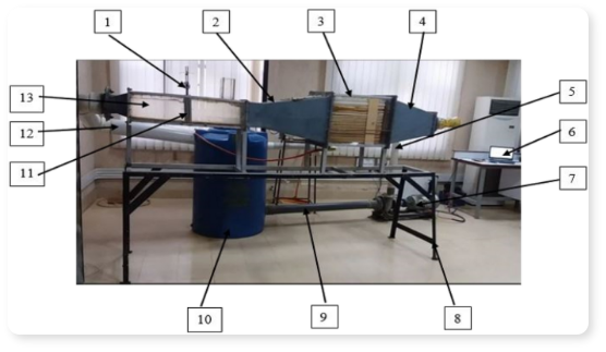
In the world of industrial engineering, heat exchangers are the unsung workhorses that keep our refineries, power plants, and chemical facilities running. These massive units—some the size of school buses—transfer thermal energy between fluids with remarkable efficiency. Inside their cylindrical shells, thousands of thin tubes, each no thicker than your thumb, carry precious fluids worth millions of dollars. While a gentle hum is normal, even expected, FIV represents something entirely different: a chaotic, high-energy instability that can transform these industrial giants into self-destructing machines.
It is engineering’s “silent killer,” capable of destroying massive infrastructure worth tens of millions of dollars in a matter of days—or even hours.
What Exactly Is Flow-Induced Vibration?
At its core, FIV is a battle between structural mechanics and fluid dynamics, a clash between the solid and the flowing. As fluid rushes across a bundle of tubes at velocities that can exceed 30 feet per second, it exerts forces—sometimes gentle, sometimes violent. Typically, the tubes are stiff enough to resist, absorbing the energy through their inherent damping capacity, like a car’s shock absorbers smoothing out bumps on a highway.
However, when the energy input from the flow overwhelms the tube’s natural ability to dissipate that energy, something sinister happens: the tubes begin to oscillate. What starts as microscopic movements can rapidly amplify into vibrations visible to the naked eye—tubes moving inches back and forth, hundreds of times per second.
The consequences are not merely operational inconveniences; they are catastrophic events that haunt the nightmares of facility managers:
Catastrophic Leaks: Vibrating tubes can shear off completely at their support points or develop fatigue cracks, allowing hazardous fluids to mix in ways nature never intended. Picture cooling water contaminating hot hydrocarbon oil, or worse, flammable gases mixing with oxygen-rich air. The result: fires, explosions, and environmental disasters.
Acoustic Resonance: In gas systems, vibration can create a “standing wave” within the shell chamber itself, generating noise levels comparable to standing next to a military jet at takeoff—130 decibels or higher. Workers have reported being unable to approach certain units without hearing protection, and the acoustic pressure alone can crack welds and fracture internal components.
Economic Devastation: The unplanned shutdown of a critical heat exchanger can cost a refinery $100,000 per hour in lost production. Emergency repairs can run into the millions. In one documented case, a chemical plant lost $8 million in a single week due to a vibration-induced failure.
The Four Mechanisms: How Physics Shakes the Tubes
Tubes do not vibrate randomly. They react to specific, well-understood physical phenomena, each with its own signature and danger profile. According to engineering literature—specifically Chapter 10 of the authoritative Heat Exchanger Design Handbook—there are four distinct mechanisms that drive this destruction.
1. Vortex Shedding (The “Flag Flapping” Effect)
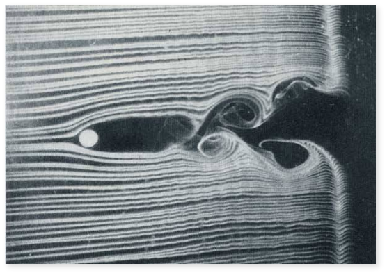
This is the most common mechanism in liquid flows, and ironically, the most beautiful when visualized in slow motion. As fluid encounters a cylindrical tube, it attempts to flow smoothly around it. But fluids, like people, struggle with sharp corners and curves. At a certain point on the tube’s surface, the boundary layer of slow-moving fluid near the wall can no longer maintain contact. It detaches, rolling up into a spinning vortex—a miniature tornado in the flow.
This phenomenon, known as the Von Karman vortex street (named after the Hungarian-American physicist Theodore von Kármán), creates alternating vortices that peel off rhythmically from the top and bottom of the tube, like smoke rings from a chimney on a calm day.
Each shedding vortex exerts a small but measurable lift force perpendicular to the flow direction. Individually, these forces are negligible. But they occur with clockwork regularity at a frequency determined by the flow velocity and tube diameter. The shedding frequency can be calculated using the Strouhal number, a dimensionless parameter that relates vortex shedding to flow conditions.
Here’s where danger enters the picture: if the shedding frequency happens to match—or even come close to—the natural vibration frequency of the tube structure, a phenomenon called “lock-in” occurs. The tube begins to resonate, extracting energy from the flow with devastating efficiency. The amplitude of vibration can grow to several tube diameters, like a flag whipping violently in a stiff breeze, cracking against its pole.
In one infamous incident at a chemical plant, vortex shedding caused tubes to fail within 72 hours of startup, each tube developing fatigue cracks at the support plates from the relentless oscillation.
2. Fluidelastic Instability (The “Runaway” Effect)
If Vortex Shedding is a dangerous nuisance, Fluidelastic Instability (FEI) is the grim reaper of heat exchangers. It is, without question, the most dangerous mechanism.
FEI represents a fundamental breakdown in the balance between fluid forces and structural resistance. It occurs when the flow velocity crosses a critical threshold, denoted as U in engineering calculations. Below this velocity, tubes might vibrate slightly but remain stable. Cross this invisible line, and all bets are off.
Beyond the critical velocity, something extraordinary and terrifying happens: the motion of the tubes begins to modulate the fluid forces acting on them in such a way that energy is continuously fed from the fluid into the vibration. The tubes essentially become coupled to the flow in a positive feedback loop. A small displacement causes increased fluid force, which causes larger displacement, which causes even greater fluid force. The vibration amplitude grows exponentially, without theoretical limit, until physical constraints intervene—usually in the form of tubes crashing violently into their neighbors.
Unlike resonance, which might be alleviated by slightly changing the flow speed or adjusting the frequency mismatch, FEI is a runaway train. Increasing velocity past U only makes it worse. The tubes will continue to absorb energy and vibrate with increasing violence until mechanical failure occurs.
The sound of FEI in action is unforgettable to those who’ve heard it: a deep, rhythmic banging as hundreds or thousands of tubes collide with one another in a chaotic dance of destruction. Maintenance workers have described it as “a giant repeatedly hitting the shell with a sledgehammer.”
The critical velocity depends on several factors: tube mass, damping, natural frequency, fluid density, and the specific arrangement of the tube bundle. Prediction requires sophisticated computational tools and conservative safety factors—typically, designers aim to operate at no more than 80% of the calculated critical velocity.
3. Turbulent Buffeting
Think of turbulent buffeting as driving a car down a washboard gravel road at high speed. The suspension absorbs most of the individual impacts, but the continuous bombardment eventually takes its toll on every component of the vehicle.
In heat exchangers operating with highly turbulent flow—Reynolds numbers exceeding 10,000—the fluid doesn’t flow smoothly. Instead, it churns with chaotic eddies and swirls across a broad spectrum of sizes and frequencies. These turbulent structures, ranging from microscopic to several tube diameters in size, bombard the tubes with random packets of energy.
Unlike the periodic, predictable nature of vortex shedding, turbulent buffeting is stochastic—random in both amplitude and frequency. The forces are spread across a wide frequency spectrum, like white noise, rather than concentrated at a single frequency.
Turbulent buffeting rarely causes immediate, dramatic failure. Its destruction is more insidious. The continuous random excitation leads to fretting wear—a slow, grinding process where tubes gradually erode at support points. Over months or years, the tube walls thin from nominal thickness (often 0.065 inches) to dangerous levels. Eventually, pressure causes a leak, or the tube simply ruptures.
The insidious nature of fretting wear is that it’s nearly impossible to predict without detailed vibration monitoring. A unit might run perfectly for five years, then fail catastrophically in year six as accumulated wear crosses a critical threshold.
4. Acoustic Resonance
Specific to gas and vapor services, acoustic resonance represents the intersection of fluid dynamics and sound physics. When dealing with compressible fluids—gases and vapors—the shell chamber itself can act as an acoustic cavity, much like the body of a guitar or the pipe of an organ.
If the vortex shedding frequency (or any other periodic excitation) synchronizes with one of the natural acoustic modes of the shell cavity, the entire volume of gas begins to resonate. Standing pressure waves form, creating zones of compression and rarefaction that oscillate at hundreds or even thousands of cycles per second.
The result is an intense, pure tone—a deafening hum or high-pitched scream that can be heard hundreds of feet away. Sound pressure levels can exceed 140 decibels inside the shell, well into the threshold of pain and permanent hearing damage.
But the noise, terrifying as it is, represents only the symptom. The real danger lies in the acoustic pressure waves themselves. These pressure oscillations can: - Fatigue and crack welds over time - Damage internal baffles and support structures - Even crack the pressure boundary of the shell itself in extreme cases
Acoustic resonance is particularly common in steam condensers, gas coolers, and vapor recovery systems. The frequency depends on the speed of sound in the gas and the dimensions of the shell cavity. Engineers must carefully check for potential acoustic resonance during design, calculating all possible acoustic modes and ensuring operating conditions avoid them.
The Danger Zones: Where Failures Happen
Vibration, like water seeking the lowest point or electricity finding the path of least resistance, is an opportunistic force. It invariably targets the weakest links in any design—the locations where support is inadequate, spans are too long, or velocities are too high.
The Baffle Window: The Achilles’ Heel
Inside the shell of a heat exchanger, metal plates called “baffles” serve a dual purpose: they support the tubes, preventing excessive spans, and they direct the shell-side flow across the tube bundle for efficient heat transfer. However, these baffles cannot be solid plates—fluid must be able to pass through the exchanger. Therefore, each baffle contains a large “window” (a cutout area, typically 15-45% of the shell diameter) to allow fluid passage.
This engineering necessity creates a structural vulnerability. Tubes passing through the baffle window lack intermediate support, resulting in unsupported spans twice as long as tubes in the supported regions. This matters because structural stiffness is exquisitely sensitive to span length.
Since the natural frequency of a tube span is inversely proportional to the square of its length  , even modest increases in span length cause dramatic drops in stiffness. A tube with a 24-inch unsupported span has only one-quarter the stiffness (and one-half the natural frequency) of the same tube with a 12-inch span.
Furthermore, the baffle window is often where shell-side velocity is highest—fluid accelerates as it passes through the restricted area, much like water speeding up in the narrow section of a river. High velocity combined with low stiffness creates the perfect storm for Fluidelastic Instability.
Experienced designers recognize the baffle window as the most critical region in any heat exchanger. Failures almost always initiate here.
The U-Bend: The Floppy Menace
In U-tube heat exchangers—a design where tubes form hairpin loops, both ends terminating in the same tubesheet—the outer perimeter tubes trace long, graceful arcs. These U-bends, while elegant from a manufacturing standpoint, present significant vibration challenges.
The outer loops can exceed 6-10 feet in total developed length, creating enormous unsupported spans. Without specific anti-vibration supports, these tubes behave more like rope than rigid pipe. Their natural frequencies can drop to single-digit hertz—low enough to be easily excited by almost any flow condition.
The solution is Anti-Vibration Bars (AVBs)—flat metal strips or formed plates inserted between the U-bend tubes to provide lateral support and increase effective stiffness. Proper AVB design is part science, part art. Too few, and the tubes remain vulnerable. Too many, and assembly becomes impossible, or thermal expansion is overly constrained, leading to different problems.
Modern design codes provide detailed guidance on AVB placement, but the fundamental challenge remains: supporting long, curved tubes in a confined space while allowing for thermal growth.
The Inlet Nozzle: The Velocity Hotspot
Every heat exchanger has an inlet—a nozzle where shell-side fluid enters the unit. This is where fluid velocity reaches its maximum, often 2-5 times the average shell-side velocity. The entering jet blasts directly onto whatever tube bundle happens to lie in its path—typically the topmost row of tubes.
This “impingement zone” experiences forces unlike anywhere else in the exchanger. Local velocities can exceed 50 feet per second, well into the danger zone for vibration. The turbulence intensity is extreme, creating both high-frequency buffeting and potentially dangerous vortex shedding.
Engineers protect this region using several strategies: - Impingement plates: Solid plates that intercept the inlet jet and dissipate its energy before it reaches the tubes - Reduced tube density: Removing tubes from the impingement zone entirely - Reinforced supports: Additional baffle plates or tie rods specifically in the inlet region
Ignoring inlet impingement is a rookie mistake that experienced designers never make.
Diagnosis and Prevention: Engineering the Solution
How do engineers stop a multi-million-dollar piece of equipment from shaking itself to pieces? The answer requires a combination of forensic detective work, rigorous mathematical prediction, and sometimes, plain old intuition born from experience.
The Warning Signs: Listening to the Machine
Before total catastrophic failure, industrial equipment almost always provides warning signs—subtle changes in behavior that the experienced operator or engineer learns to recognize. Heat exchangers are no exception.
Audio Cues: Sound tells a story. A pure, sustained tone—like a note from a massive organ pipe—strongly suggests acoustic resonance. The frequency of the tone can even reveal which acoustic mode has been excited. By contrast, a harsh rattling or banging sound indicates mechanical contact: tubes clashing against each other or against support structures. Experienced operators can distinguish between “normal” operational sounds and the ominous changes that precede failure.
Pressure Drop Changes: Vibration extracts energy from the flowing fluid. This energy extraction manifests as an increase in pressure drop across the exchanger. If the differential pressure rises suddenly or gradually over time without a corresponding change in flow rate or fluid properties, vibration may be the culprit. An unexplained 10-15% increase in pressure drop is a red flag.
Temperature Anomalies: Severe vibration can alter flow patterns, creating dead zones or preferential flow paths that degrade heat transfer performance. If outlet temperatures begin to drift from design values, or if thermal performance degrades without an obvious cause like fouling, vibration-induced flow maldistribution might be occurring.
Forensic Analysis: Modern diagnostic tools allow engineers to peer inside the black box. Accelerometers mounted on the shell can measure vibration transmitted through the structure. The resulting data, displayed as a “waterfall plot” showing vibration amplitude versus frequency over time, reveals whether vibration peaks align with calculated vortex shedding frequencies, natural frequencies, or acoustic modes. This forensic approach can identify problems before catastrophic failure occurs.
Engineering the Fix: Making It Stiffer
The most fundamental and effective strategy for preventing flow-induced vibration is deceptively simple: make the structure stiffer. The natural frequency of a tube, which determines its resistance to resonance and fluidelastic instability, depends primarily on its unsupported length.
The relationship is unforgiving:
This inverse square relationship means that even modest reductions in unsupported length yield massive increases in stiffness and natural frequency. Halving the span length quadruples the stiffness—a tremendous improvement from a relatively simple modification.
Practical strategies include:
Shortening Spans: Adding intermediate support plates (baffles) is the gold standard for vibration prevention. If tubes are failing with a 36-inch baffle spacing, reducing to 24 inches increases the natural frequency by a factor of 2.25—often enough to move the design into a safe operating regime. The trade-off is increased shell-side pressure drop and higher manufacturing costs, but these are small prices compared to catastrophic failure.
No-Tubes-In-Window (NTIW): This design philosophy takes a radical approach to the baffle window vulnerability: if the unsupported spans in the window are problematic, simply eliminate tubes from that region entirely. The NTIW design removes all tubes from the baffle window areas, leaving only the well-supported tubes in the baffle-contact regions. While this reduces the total heat transfer area (requiring a larger exchanger to achieve the same duty), it virtually eliminates the primary failure zone. NTIW is increasingly the design standard for severe vibration services.
Tube Staking: For existing units in the field, replacement may be economically or logistically impossible. Engineers have developed a clever retrofit solution: tube stakes, which are essentially U-shaped metal hairpins inserted between tubes in vulnerable regions. The stakes add friction damping and lateral support without requiring complete disassembly or retubing. While not as effective as proper baffle plates, stakes have saved countless exchangers from premature failure.
Material and Geometry Optimization: Increasing tube wall thickness, switching to stiffer tube materials, or using smaller diameter tubes all increase natural frequency. However, these changes have cost and heat transfer implications that must be carefully balanced.
The Complexity of Two-Phase Flow: When Things Get Weird
All of the mechanisms and solutions discussed thus far become exponentially more complicated when the fluid is not purely liquid or purely gas, but a mixture of both—a two-phase flow. This occurs in boilers (water evaporating to steam), condensers (steam condensing to water), reboilers, and countless other industrial applications.
Two-phase flow introduces a diabolical level of complexity because the fluid properties—density, viscosity, velocity—change continuously and unpredictably along the flow path. A design that appears safe when the void fraction (percentage of gas) is 30% might vibrate violently when the void fraction reaches 70%, even though the mass flow rate hasn’t changed.
The reason lies in damping. Liquid provides excellent vibration damping—it’s thick, viscous, and has mass that resists acceleration. Gas, by contrast, provides almost no damping. It’s too light and non-viscous to effectively dissipate energy from vibrating tubes. As a mixture transitions from liquid-dominated to gas-dominated, the system damping can drop by a factor of 10 or more, dramatically increasing vibration susceptibility.
Furthermore, two-phase flow can exhibit unstable flow regimes that compound the problem. Slug flow, where large plugs of liquid travel at high gas velocities, subjects tubes to severe impact loading—imagine being repeatedly struck by a water balloon traveling at 60 mph. Annular flow, where liquid films the tube walls while gas travels at high velocity in the core, creates complex force distributions that are difficult to predict.
The velocities themselves become ambiguous: should we use the superficial gas velocity? The superficial liquid velocity? Some weighted average? Engineers have developed specialized correlations and methods for two-phase systems, but they remain the most challenging vibration cases to analyze.
Closing Thoughts: Respecting the Silent Killer
Flow-Induced Vibration stands as a humbling reminder that in engineering, static structures are rarely truly static. Invisible forces—the turbulent eddies in a gas stream, the rhythmic shedding of vortices, the acoustic pressure waves in a vapor space—can accumulate and amplify into destructive violence.
The challenge involves a complex interplay of structural dynamics, fluid mechanics, heat transfer, and materials science. No single equation or simple rule can guarantee safety. Success requires rigorous prediction using sophisticated computational tools (Computational Fluid Dynamics coupled with Finite Element Analysis), conservative design margins (the ubiquitous 80% rule—stay below 80% of critical velocity), and validation through prototype testing or field experience.
Yet despite this complexity, or perhaps because of it, the principles remain comprehensible. Engineers armed with understanding—of vortex streets, resonance, critical velocities, and support strategies—can tame this silent killer.
By listening carefully to the machinery (both literally and figuratively), by understanding the physics of the invisible battle between fluid and structure, and by designing with humility about what we cannot perfectly predict, engineers ensure that our industrial infrastructure remains safe, efficient, and mercifully quiet.
The Tacoma Narrows Bridge collapsed because its designers underestimated the power of aerodynamic forces. We need not repeat that mistake in our heat exchangers. The silent killer can be silenced—through knowledge, vigilance, and respect for the immense forces hidden within the flow.

FAQ
FAQ 1: What is Flow-Induced Vibration (FIV) and why is it dangerous?
Flow-Induced Vibration occurs when fluid flowing across heat exchanger tubes exerts forces that cause the tubes to oscillate. When the energy from the flow exceeds the tube's ability to dissipate it, vibrations can rapidly amplify, leading to catastrophic failures including tube ruptures, hazardous fluid leaks, fires, and explosions. A single FIV incident can cost millions in repairs and lost production—one chemical plant lost $8 million in just one week due to vibration-induced failure.
FAQ 2: What causes tubes to vibrate in heat exchangers?
There are four main mechanisms: (1) Vortex Shedding creates alternating vortices that can cause resonance when their frequency matches the tube's natural frequency; (2) Fluidelastic Instability is the most dangerous—a runaway feedback loop where tube motion amplifies fluid forces exponentially once flow exceeds a critical velocity; (3) Turbulent Buffeting causes random, continuous bombardment leading to gradual fretting wear; and (4) Acoustic Resonance in gas systems creates standing pressure waves that generate extreme noise and can crack welds.
FAQ 3: How can engineers prevent Flow-Induced Vibration?
The most effective strategy is increasing tube stiffness by reducing unsupported spans—halving the span length quadruples the stiffness. Practical solutions include adding intermediate support plates (baffles), using No-Tubes-In-Window (NTIW) designs that eliminate tubes from vulnerable baffle window regions, installing impingement plates at inlet nozzles, and retrofitting existing units with tube stakes. Engineers also monitor warning signs like unusual sounds, pressure drop changes, and temperature anomalies to catch problems before catastrophic failure occurs.
Keep Learning
Simultaneous Dual-Frequency Induction Heating: When One Frequency Forces the Wrong Compromise
Key Takeaways One frequency, one compromise: When geometry demands both deep bulk heating and controlled surface gradients simultaneously, a single frequency forces an unacceptable trade-off—dual-frequency widens the process window. Give each channel a role: Assign the lower frequency to bulk penetration and the higher frequency to surface shaping. Structured recipe development follows naturally from this separation. Validate with metrics, not opinions: Dual-frequency is justified only when controlled......
Power Supplies by Application Family: Joining, Mass Heating, and Strip Processing
Key Takeaways Joining operations (brazing, soldering, bonding) demand higher frequencies and matching flexibility to handle variable coil coupling and precision surface heating. Mass heating lines (billets, bars, slabs) prioritize continuous duty, efficiency, and ruggedness at high power levels with multi-coil zone control. Strip processing requires architectures that separate control electronics from high-frequency inverter modules to cope with harsh installation environments. Specifying only kW and ......
Simultaneous Dual-Frequency Induction Power: When One Frequency Forces the Wrong Compromise
Key Takeaways Dual-frequency is justified by robustness, not complexity: It should only be adopted when a single frequency forces an unacceptable compromise between surface and bulk heating requirements. Give each frequency a defined role: Assign the lower frequency to bulk heating/penetration and the higher frequency to surface shaping—then develop recipes one variable at a time. The combining network is the engineering center of gravity: Frequency-selective coupling paths, thermal rating for worst-c......
Applying Induction Power Supplies in the Real World: Constraints That Decide Uptime and Quality
Key Takeaways Application constraints dominate real-world performance: Two induction systems with identical kW ratings can behave very differently depending on cable length, cooling water temperature, dust levels, and fixture repeatability. Design for drift, not for perfect day one: Coils deform, filters clog, sensors drift, and connectors loosen under thermal cycling. Baseline monitoring during commissioning is essential. Mechanical repeatability often beats control complexity: Improving fixturing an......
Medium- and High-Frequency Transformers in Induction Systems: Design Drivers Engineers Should Actually Care About
Key Takeaways Not Passive: Transformers set the electrical operating point for the entire induction station—coil voltage, current, capacitor stress, and inverter margin all depend on transformer choice. Frequency Effects: At higher frequencies, winding losses and stray capacitance dominate; a transformer that looks fine on turns ratio can fail a duty-cycle test if loss distribution is wrong. Placement Matters: Moving the transformer and capacitor bank closer to the coil reduces high-frequency loop len......
Load Matching in Induction Heating: Designing for Stability, Efficiency, and Real-World Variation
Key Takeaways Dynamic Load: Induction heating loads are not fixed—coupling, material properties, and temperature all shift impedance during operation, making matching a continuous design challenge. Q Factor Matters: High-Q loads can produce large circulating currents and capacitor stress even at modest delivered kW; design for the worst-case kVA, not just power. Discrete Ranges Win: Transformer taps and capacitor steps that cover discrete matching ranges outperform a single broad-range configuration f......