
The Iron Skeleton of Heat Transfer: Why Mechanical Design Matters More Than You Think
11 min
- TEMA: The Specialist
- ASME: The Law
- FAQ
When we talk about heat exchangers—those massive industrial organs responsible for transferring energy in power plants, refineries, and chemical facilities—the conversation almost always gravitates toward thermal performance. Engineers ask: "How fast can this cool down?" or "How many megajoules can we recover per hour?" Efficiency charts get drawn, heat transfer coefficients get debated, and everyone goes home feeling productive.
But there is a darker, more critical side to engineering these machines. While thermal design determines how well a unit works, mechanical design determines whether it survives.
A heat exchanger is, at its core, a pressurized vessel waiting for a weakness to exploit. It contains volatile fluids at extreme temperatures and crushing pressures, operating not for hours, but for decades. Mechanical design is the discipline that transforms thermal requirements into physical reality—ensuring that these industrial giants don't just perform, but endure.
The Core Mission: Safety in a Pressure Cooker
Imagine a pressure cooker the size of a school bus, operating continuously for 20 years, enduring earthquakes, hurricane-force winds, and internal fluids that might be corrosive, flammable, or outright explosive. That is the challenge of mechanical design.
The objectives form a "Holy Trinity" of engineering:
Safety & Compliance is the absolute priority. A leak or explosion isn't just an operational hiccup; it's a threat to human life, and potentially a mile-wide exclusion zone. Every decision flows from this foundation.
Durability means surviving the invisible enemies: corrosion quietly eating the metal from within, erosion wearing it down where fluid velocity is highest, and thermal cycling—the relentless expansion and contraction that works like bending a paperclip back and forth until it snaps.
Maintainability is the design consideration most often neglected—and most bitterly regretted. If you can't open a unit to clean it, inspect it, or replace a gasket, it becomes a liability rather than an asset. Good mechanical design accounts for the humans who will wrestle with the machine years down the line, often at 2 a.m. during an unplanned shutdown.
The Rulebook: Design Isn't a Free-for-All
You cannot sketch a heat exchanger on a napkin and build it. The industry is governed by rigorous international codes—the unwritten constitution of mechanical engineering, made very much written.
TEMA: The Specialist
The Tubular Exchanger Manufacturers Association (TEMA) sets the specific rules for shell-and-tube exchangers. They classify equipment based on the severity of the service:
Class R (Refinery): The heavyweights. Built for the harsh, punishing environments of oil processing, where a failure can cascade into catastrophe.
Class C (Commercial): The reliable workhorses of general industry—cost-effective and proven.
Class B (Chemical): Specialized units, often requiring exotic materials like Hastelloy or titanium for specific chemical duties.
ASME: The Law
The ASME Boiler and Pressure Vessel Code (Section VIII) is the global heavyweight champion of safety standards. It dictates the mathematics behind wall thickness and weld quality.
Division 1 uses "Design-by-Rule"—conservative, time-tested formulas that result in thicker, inherently safer walls. Division 2 allows "Design-by-Analysis"—using advanced computer simulations to optimize every gram of material, yielding lighter, more precise designs for engineers willing to prove their case with numbers. Think of Division 1 as the cautious general and Division 2 as the brilliant tactician who needs to justify every move.
The Workflow: From Concept to Steel
How does an engineer move from a spreadsheet full of process data to a fabrication drawing? It is a sequential logic gate, where each step informs the next and a mistake early on compounds painfully later.
Define the Inputs. We don't design for the normal operating pressure alone—we design for Design Pressure, typically set 10–15% higher than the maximum operating condition, plus a buffer for upset scenarios. We also add a Corrosion Allowance: literally specifying extra millimeters of steel whose sole purpose is to be sacrificed to rust over the vessel's 20-year life.
Identify All Loads. Internal pressure is only the beginning. What if an earthquake strikes? What about the weight of massive connecting pipework bearing down on the nozzles? What about wind loads on a tall vertical vessel, or the thermal shock of a cold fluid charge into a hot shell? Each load must be identified, quantified, and designed against.
Select Materials. The metal must match the fluid. Carbon steel is cheap and abundant, but seawater demands titanium. Hydrogen service requires steels with tightly controlled chemistry to prevent embrittlement. Getting this wrong doesn't cause immediate failure—it causes slow, invisible degradation that manifests years later, at the worst possible moment.
Calculate Thickness. Using code formulas, engineers determine exactly how thick the shell, heads, and nozzles must be to keep stress below the material's Allowable Limit—the ceiling beyond which permanent deformation begins.
Verify the Welds. Welds are assigned a Joint Efficiency factor. If every inch of a weld is X-rayed (full radiography), the code trusts it more, allowing slightly thinner walls. Skip the X-ray, and the code penalizes you with a heavier vessel. It's a direct, elegant trade-off between inspection cost and material cost.
Stress: The Invisible Enemy
Not all stress is created equal, and the distinction is what separates a competent mechanical engineer from a dangerous one.
Primary Membrane Stress is the average stretching of metal due to pressure—the "balloon effect." It is dangerous and non-self-limiting. If it exceeds the material's yield strength, the vessel doesn't spring back; it bulges and eventually ruptures. We guard against it with safety factors of 3.5 or higher.
Primary Bending Stress acts like bending a ruler. It causes distortion and is allowed slightly higher limits than membrane stress, but it remains strictly controlled, particularly at nozzle connections and support saddles.
Secondary Stress arises when metal wants to expand due to heat but is physically restrained by the surrounding structure. Crucially, this type is self-limiting: once the metal yields slightly and redistributes the load, the stress is relieved. The code is correspondingly more generous here, recognizing that a little local yielding is not a catastrophe.
Peak Stress is the most insidious category. It lives at sharp corners, weld toes, and abrupt geometric changes—invisible on a drawing, but intensely real in the metal. It won't cause immediate failure, but under thousands of pressure cycles and temperature swings, it seeds microscopic cracks that grow, millimeter by millimeter, until one day the vessel fails long before its design life expires. This is fatigue, and designing against it requires thinking about not just today's load, but every load the vessel will ever see.
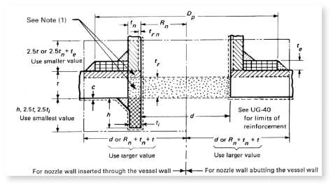
The Tubesheet: The Swiss Cheese Paradox
The tubesheet is perhaps the most fascinating single component in a shell-and-tube exchanger. It is a thick metal plate drilled with hundreds—sometimes thousands—of holes to accept the tube ends. And therein lies its fundamental paradox.
To resist the pressure differential between the shell side and tube side, you need a massive, rigid plate. But to hold the tubes, you must drill away a substantial fraction of that material. This is the Ligament Efficiency problem: the more holes you drill, the weaker the plate becomes. Engineers must thread a needle between a plate stiff enough to resist bending and light enough to not be prohibitively expensive.
The problem deepens with thermal behavior. In a U-tube design, the tubes are bent into a hairpin shape and free to expand independently of the shell—an elegant mechanical solution that dramatically reduces thermal stress. In a fixed tubesheet design, the tubesheets are welded directly to the shell, creating a rigid assembly. When the shell and tubes experience different temperatures and try to expand at different rates, they fight each other like two stubborn people pulling on opposite ends of a rope, generating enormous structural loads that must be accounted for in every calculation.
Geometry Matters: Heads and Shells
The shell is a simple cylinder, but you need to cap the ends. The shape you choose is a battle between physics, economics, and the laws of geometry.
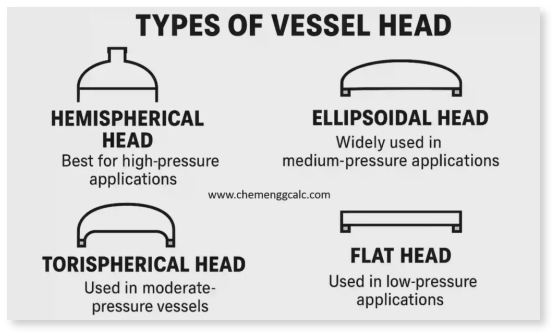
Hemispherical heads are the theoretical ideal. A sphere distributes pressure perfectly evenly across its surface, requiring walls only half as thick as a cylinder of the same diameter. The catch: forming a perfectly curved steel hemisphere is expensive and time-consuming, reserved for the most extreme pressures.
Ellipsoidal (2:1) heads are the industry's everyday workhorse—a smoothly curved shape that strikes an excellent balance between strength, internal volume, and fabrication cost. If you've seen the domed ends of a propane tank, you've seen this geometry.
Torispherical heads are cheaper still, but carry a hidden cost: a sharp "knuckle" radius where the dished portion meets the cylindrical flange. Stress concentrates at this knuckle, making torispherical heads unsuitable for high-pressure service. The savings at the fabrication shop can be paid back with interest in maintenance costs.
Flat covers are geometrically the weakest option—a flat plate resists pressure purely by bending, like a trapdoor holding back a flood. It must be made extraordinarily thick to survive any meaningful pressure. But their saving grace is access: unbolt a flat cover and the entire interior of the vessel is immediately accessible. For heat exchangers that require frequent cleaning or inspection, that convenience can be worth the weight penalty.
The Final Exam: Reality Checks
Before any design is released for fabrication, it must pass a series of unglamorous but essential "sanity checks" that no simulation can fully replicate.
Can it actually be built? Are the tolerances realistic, or will the assembly require millimeter-perfect alignment across a six-meter shell? Can the lifting lugs handle the full weight of the bundle during a maintenance pull? A beautiful design that cannot be manufactured or maintained is not a good design—it is an expensive problem deferred to someone else.
And finally, the Hydrotest. Before a heat exchanger ever sees a drop of process fluid, it is filled with water—a deliberately incompressible fluid that won't explosively release energy if something fails—and pressurized to 1.3 or 1.5 times its design limit. Every weld, flange, and fitting is observed under this elevated load. Water weeps from a pinhole. A flange face shows damp staining at a gasket improperly seated. The hydrotest catches what calculations might miss, and it has been the final guardian of mechanical integrity for well over a century.
Only when the metal holds, the flanges seal, and the welds remain bone dry does the mechanical designer's job truly end.
Mechanical design is ultimately the art of predicting the future—of foreseeing 20 years of pressure cycles, thermal shocks, corrosion, and seismic events, and building a vessel that greets those extremes as simply another day at the office. It is less glamorous than thermal optimization, rarely discussed at conferences, and almost never mentioned when a plant runs smoothly. It only enters the conversation when something goes wrong. Which is precisely why it must be done right the first time.

FAQ
Q1: What's the main difference between a regenerator and a recuperator?
A recuperator continuously transfers heat through a metal wall (like a car radiator), while a regenerator works in cycles—it stores heat in a solid matrix during one phase, then releases it during another. Think of it as a "thermal battery" that catches, holds, and releases heat precisely when needed, achieving 85-95% efficiency in extreme conditions.
Q2: Why can't regenerators be used in clean rooms or food processing?
Regenerators have an inherent contamination issue: the same matrix contacts both dirty exhaust and fresh intake air. This causes 1-5% carryover—residual gas from one stream mixing into the other. While acceptable for steel mills and glass furnaces, this cross-contamination is a dealbreaker for applications requiring strict purity, like hospitals or semiconductor fabrication.
Q3: Why is mechanical design as critical as thermal performance in heat exchangers?
A heat exchanger is essentially a pressurized vessel operating under extreme conditions for decades. While thermal design determines efficiency, mechanical design ensures survival. Engineers must account for internal pressure, corrosion, thermal expansion, earthquakes, and fatigue. Poor mechanical design doesn't just reduce performance—it can lead to catastrophic failure. That's why strict codes like ASME and TEMA govern every calculation, from wall thickness to weld quality.
Keep Learning
How Transparent Graphene Heaters Clear Fogged Glass
Key Takeaways Atom-thin transparency: A single graphene layer transmits about 97.7% of visible light, while five stacked layers still pass roughly 87.3%, making the heater nearly invisible on glass or plastic. Fast, controllable heating: A monolayer device reaches its target temperature with a thermal time constant of only about 6–7 seconds, and input power can be adjusted to hold temperatures from 38 °C up to around 80 °C. Efficiency advantage: Graphene heaters achieved higher temperatures at the sam......
Process Control, Monitoring, and Quality Assurance in Induction Heating: Reducing Risk Without Cutting Every Part
Key Takeaways Separate control from monitoring: A control system executes the recipe; a monitoring system independently verifies what actually happened. Independence turns logs into evidence. Monitor intermediate variables: You can't measure fatigue strength inline, but you can measure delivered kW, frequency stability, position, and quench variables—then compare each cycle to a validated "good envelope." Signature monitoring beats single thresholds: Time-series signatures capture ramps, holds, and tr......
Cooling Induction Power Supplies: Designing the Thermal System That Protects Your Electrical System
Key Takeaways Cooling is a first-class subsystem: Many "electrical" failures in induction lines are actually thermal problems—drifting water temperature, clogged filters, or unbalanced branch flow. Measure at the branch, not the header: A healthy header can mask a starved branch. Branch flow to the highest-loss modules is the single most useful cooling measurement. Trend cooling like a process variable: Baseline flow, temperature, and filter pressure drop during commissioning, then trend them to turn ......
Independent Frequency and Power Control in Induction Inverters: Turning Frequency Back Into a Process Variable
Key Takeaways Frequency as a process variable: Independent frequency and power control decouples resonance supervision from kW regulation, letting engineers set frequency based on process physics rather than control mechanics. Measurable validation: Prove independent control with three commissioning tests—fixed-frequency power steps, fixed-kW frequency sweeps, and coupling variation stability. Production consistency: Stable frequency improves recipe portability, reduces hidden process changes, and mak......
Simultaneous Dual-Frequency Induction Heating: When One Frequency Forces the Wrong Compromise
Key Takeaways One frequency, one compromise: When geometry demands both deep bulk heating and controlled surface gradients simultaneously, a single frequency forces an unacceptable trade-off—dual-frequency widens the process window. Give each channel a role: Assign the lower frequency to bulk penetration and the higher frequency to surface shaping. Structured recipe development follows naturally from this separation. Validate with metrics, not opinions: Dual-frequency is justified only when controlled......
Power Supplies by Application Family: Joining, Mass Heating, and Strip Processing
Key Takeaways Joining operations (brazing, soldering, bonding) demand higher frequencies and matching flexibility to handle variable coil coupling and precision surface heating. Mass heating lines (billets, bars, slabs) prioritize continuous duty, efficiency, and ruggedness at high power levels with multi-coil zone control. Strip processing requires architectures that separate control electronics from high-frequency inverter modules to cope with harsh installation environments. Specifying only kW and ......