
Magnetic Flux Control in Induction Heat Treating: Concentrators, Shunts, Intensifiers, and Shields
14 min
- Electromagnetic Shielding: Reflection vs. Absorption Mechanisms
- Magnetic Shunts: The Low-Reluctance Path
- A Taxonomy of Flux Control: Distinguishing the Hardware
- Magnetic Flux Concentrators: Materials and Mechanics
- Practical Selection and Placement Guide
- Lifecycle Management and Operational Reliability
- FAQ about Magnetic Flux Control in Induction Heat Treating
Key Takeaways
Shielding Mechanisms: Induction heat treating requires precise magnetic flux control through two physical mechanisms—reflection (dominant at high frequencies) and absorption (dominant at low frequencies)—to protect surrounding equipment from parasitic heating.
Hardware Taxonomy: Shields block/attenuate stray fields, shunts provide low-reluctance return paths, and concentrators/intensifiers actively squeeze flux into target heating zones. Each serves a distinct engineering purpose defined by its interaction mechanism.
Material Selection by Frequency: Operating frequency dictates material choice: laminated steel below 30 kHz, powdered metal composites from 30–100 kHz, and ferrite-based materials above 100 kHz. Absorption shields should follow the 4× skin-depth rule for effective attenuation.
Lifecycle Reliability: Thermal degradation, mechanical vibration, adhesive performance, and corrosion control are critical factors affecting the long-term reliability and effectiveness of flux control hardware in industrial environments.
In the sophisticated world of induction heat treating (IHT), the mastery of magnetic flux is the dividing line between an efficient, repeatable process and one plagued by parasitic losses and metallurgical inconsistencies. Magnetic flux, defined as the total number of imaginary magnetic field lines crossing a chosen surface, is the invisible currency of induction. While these lines are mathematical constructs, their physical distribution determines exactly where heat is generated within a workpiece and where energy is wasted in the surrounding machinery.
Engineers frequently encounter the "unruly" nature of magnetic fields: flux lines naturally seek the path of least resistance (reluctance), often spreading far beyond the target zone to couple with tool fixtures, machine frames, or adjacent part features. This stray flux causes "parasitic" heating, which can damage sensitive electronics, soften previously hardened regions (temper back), and reduce the overall electrical efficiency of the system. To combat these issues, a specialized taxonomy of flux control hardware—including shields, shunts, concentrators, and intensifiers—is employed to squeeze, direct, or block these fields. This expanded guide delves into the physics, material selection, and practical integration of these critical components.
Electromagnetic Shielding: Reflection vs. Absorption Mechanisms
The primary goal of electromagnetic shielding is to protect the perimeter of the induction process from stray alternating current (AC) fields. When an incident magnetic wave hits a conductive or permeable boundary, its energy is attenuated through two primary physical mechanisms: reflection and absorption. The choice between these mechanisms is almost entirely dictated by the operating frequency of the induction system. In industrial environments, stray fields can interfere with sensors, pyrometers, and robots, making shielding a necessity for system reliability.
The Physics of Shielding Effectiveness (SE)
The performance of a shield is quantified in decibels (dB) using the ratio of the incident wave strength ($H_1$) to the attenuated wave strength ($H_2$). The logarithmic nature of this scale means that small numerical increases represent massive improvements in performance. For instance, a 20-dB shield reduces the field strength by a factor of 10, whereas a 40-dB shield reduces it by a factor of 100. In practical terms, a 60-dB shield is often required for high-frequency work to ensure sensitive electronic components in the vicinity are completely isolated from the electromagnetic field.
In practical engineering, the total effectiveness (SE) is the sum of three distinct factors: reflection (R), absorption (A), and a correction factor (B) for multiple reflections inside thin shields:
$$SE = R + A + B$$
At high frequencies, R is the heavy lifter. At low frequencies, A becomes the primary contributor. A critical engineering "rule of thumb" for absorption shielding is to ensure the shield thickness is at least four times the reference depth (skin depth, $\delta$) of the frequency being used. This thickness generally guarantees an attenuation of approximately 35 dB, which is sufficient for most industrial applications. When working with copper shields, reaching 40 dB at 10 kHz typically requires one full reference depth of thickness.

Magnetic Shunts: The Low-Reluctance Path
While shields are designed to block or reflect energy away from a region, magnetic shunts serve a different purpose. A magnetic shunt generally consists of a large stack of thin steel laminations placed along the axis of an inductor and parallel to it. The fundamental goal of a shunt is to provide a low-reluctance path for the magnetic flux. By offering a "preferred" route for the field lines, the shunt effectively captures the external magnetic field that would otherwise spread into the surrounding environment. This prevents the heating of neighboring metallic structures, such as machine frames or quench tanks, which can be a significant source of energy loss.
The construction of shunts is a meticulous process. They are typically made from grain-oriented or non-oriented nickel-iron or silicon-iron alloys. These materials are chosen for their high magnetic permeability and high saturation flux density, often ranging from 1.4 to 1.9 Tesla. To minimize internal power dissipation caused by eddy currents, the shunt is not a solid block of metal but a stack of individual laminations. Each lamination is insulated with a mineral or organic coating. The thickness of these laminations is critical; for frequencies below 500 Hz, they may be 0.3 mm thick or greater, while higher frequency applications (up to 30 kHz or even 50 kHz with nanotechnology) require much thinner sheets, typically between 0.06 mm and 0.2 mm.
Practical Shunt Implementation
When implementing shunts, engineers must consider the mechanical and thermal stresses involved:
Clamping Forces: Shunts must be firmly clamped to prevent vibration caused by massive electromagnetic forces. Loose laminations can lead to mechanical damage and significant noise.
Cooling Requirements: Shunts can be a source of significant power dissipation. Depending on the power density and duty cycle, they may require active water cooling or specialized air-flow paths.
Placement Intent: Shunts are placed parallel to the inductor's axis to capture the longitudinal flux loops, ensuring the return path is contained within a high-permeability medium rather than the surrounding air.
A Taxonomy of Flux Control: Distinguishing the Hardware
In the field, the terms "shield," "shunt," "concentrator," and "intensifier" are sometimes used interchangeably, but they represent distinct engineering strategies. Understanding these differences is vital for selecting the correct tool for a specific problem. The taxonomy is primarily defined by the hardware's intent and its interaction with the magnetic field loops.
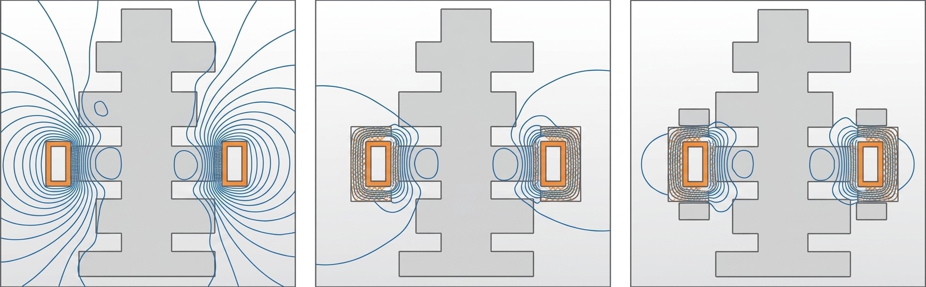
The "concentrator" or "intensifier" is often the most complex. While a shunt captures the return flux to prevent external heating, a concentrator is placed on or very near the induction coil itself. Its goal is to change the reluctance of the magnetic circuit so that the field lines are concentrated on the surface of the inductor facing the workpiece. This phenomenon, often called the "electromagnetic slot effect," results in higher current densities on the active face of the inductor, leading to improved electrical efficiency and faster heating cycles. In some applications, a single component may perform multiple roles—acting as a concentrator for the heating zone while simultaneously shielding the surrounding equipment.
| Device Type | Primary Function | Interaction Mechanism | Common Materials |
|---|---|---|---|
| Electromagnetic Shield | Block/Attenuate stray fields from reaching a specific area. | Reflection (high freq) or Absorption (low freq). | Copper, Aluminum (Reflect); Carbon Steel (Absorb). |
| Magnetic Shunt | Provide a low-reluctance return path for the flux. | Redirection of external field loops parallel to the axis. | Steel laminations (Silicon-Iron, Nickel-Iron). |
| Flux Concentrator / Intensifier | Direct and "squeeze" flux into a targeted heating zone. | Low-reluctance path actively drawing field lines to the work. | Powdered composites, Ferrites, specialized Laminations. |
Magnetic Flux Concentrators: Materials and Mechanics
Magnetic flux concentrators are designed to provide a low-reluctance path that actively draws the magnetic field lines toward the desired heating zone. This effect is analogous to how a lens focuses light or how a high-permeability core directs flux in a transformer. By providing this path, the concentrator reduces "flux leakage"—the portion of the magnetic field that does not thread through the workpiece. Reducing this leakage is a primary driver for improving the power factor of the induction system and reducing the overall current requirements for the inductor.
These components are typically fabricated from high-permeability, low-conductivity soft-magnetic materials. Their soft-magnetic nature ensures they only exhibit magnetism in the presence of an external AC field, switching their domain orientation rapidly with each cycle. This rapid switching requires materials with narrow hysteresis loops to minimize energy loss and internal heat generation. In the absence of an external field, the magnetic domains are randomly arranged, resulting in negligible magnetization. Once the AC field is applied, the domains rearrange to match the field, behaving as temporary magnets that steer the flux loops.
Material selection is dictated by the operating frequency and the required magnetic saturation. Silicon-steel laminations are the traditional choice for lower frequencies (typically below 30 kHz), while iron- or ferrite-based powder composites are preferred for high-frequency applications. Modern advancements, such as nanocrystalline alloys (e.g., NANO material), have expanded the range of laminations up to and exceeding 50 kHz. These materials offer a Curie temperature of roughly 570°C and incredibly low coercive force (0.04 Oersted), making them highly efficient. Ferrites, while offering high permeability at weak fields, are brittle and have low saturation flux densities (3000 to 4000 G), limiting their use in high-power density induction hardening.
Case Study: Eliminating Temper Back in Camshaft Hardening
One of the most challenging problems in induction hardening is the "bleeding" of heat into adjacent regions of a complex part. In camshaft production, hardening one lobe often causes stray flux to couple with the previously hardened adjacent lobe. This is particularly problematic when the surface of the lobe being heated reaches its Curie temperature; at this point, the relative permeability drops to 1, and the lobe becomes non-magnetic. Because the adjacent, previously hardened lobes remain magnetic, they may actually "attract" more of the stray flux, leading to localized heating that exceeds the tempering temperature.
By integrating a U-shaped magnetic flux concentrator around the inductor, the external field is significantly suppressed. The flux lines are "squeezed" toward the target lobe, increasing coupling efficiency while simultaneously acting as a magnetic shield for the surrounding geometry. Engineering data suggests that this approach can reduce the power density induced in adjacent features by a factor of 4 to 12 compared to a bare induction coil. Further refinements can be made by combining U-shaped concentrators with "Faraday rings" (also known as robber rings) to further trap and dissipate the leakage flux before it reaches critical part features.
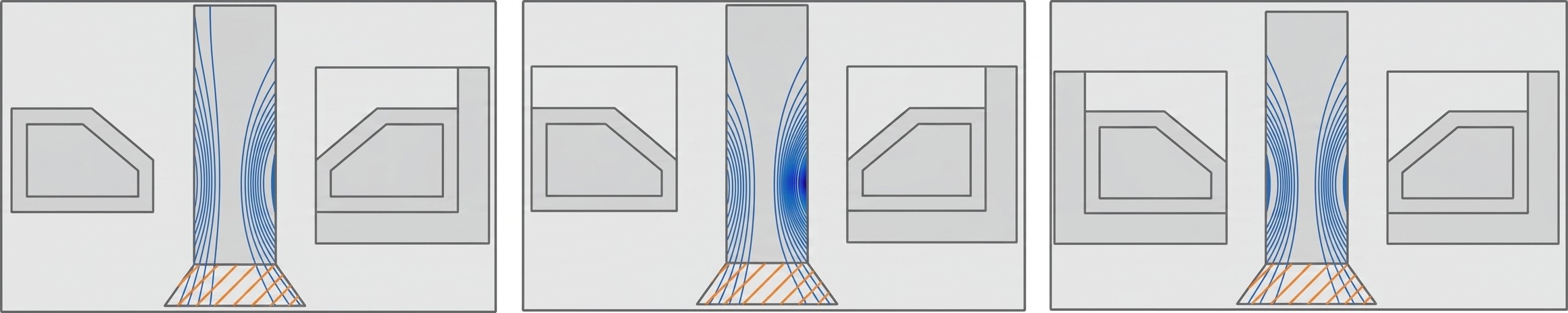
Case Study: Precision Selective Heating of Fasteners
For components like high-strength fasteners, heat treating must be restricted to specific axial zones (e.g., the threaded section) without softening the head or flange. Computer modeling illustrates how the geometry of the concentrator—whether L-shaped or U-shaped—directly dictates the heat source distribution. A U-shaped encircling concentrator provides the most effective "uninterrupted magnetic path," ensuring that the majority of the electromagnetic energy is deposited precisely where needed. This configuration not only increases the heating intensity in the required region but also reduces the axial heat-affected zone (HAZ), preventing undesirable softening of the fastener head.
Practical Selection and Placement Guide
The decision to use flux control hardware should be based on a rigorous assessment of the induction process. Not every application benefits from these components; for instance, solenoid coils used for heating long billets or rods often see little to no efficiency gain from concentrators. However, for "electromagnetically short" coils, pancake inductors, or bore heaters, the improvement can be dramatic. The following selection and placement criteria should guide the design process.
Frequency Range and Material Selection
The operating frequency is the primary filter for material choice. While boundaries are shifting due to nanotechnology, the following industrial norms generally apply:
Line Frequency to 30 kHz: Laminated steel stampings are highly effective and cost-efficient. Thicker laminations (0.3 mm+) are used for very low frequencies, while 0.1 mm to 0.2 mm sheets are standard for the higher end of this range.
30 kHz to 100 kHz: Powdered metal composites (iron-based) provide a balance of machinability and low eddy current losses. Some specialized thin-gauge laminations may also be used.
>100 kHz: Ferrite-based composites or pure ferrites are preferred due to their high electrical resistivity, which prevents overheating at high frequencies.
The 4× Skin-Depth Rule for Absorption Shields
When designing shields that operate on the principle of absorption (typically for frequencies below 10 kHz), the thickness of the material is the most critical variable. Engineering experience has established a reliable rule of thumb: the shield thickness should be approximately four times the reference depth (skin depth, $\delta$) of the operating frequency. This thickness ensures that the magnetic field is attenuated by roughly 35−40 dB, which is sufficient to protect neighboring metallic fixtures from significant heating. If the shield is too thin, the field will "leak" through, leading to parasitic losses and potential damage to the machine structure. For reflection-based copper shields at higher frequencies, the location of the shield relative to the inductor is far more critical than its absolute thickness, as the reflection mechanism occurs at the surface.
Lifecycle Management and Operational Reliability
Selecting the right material for flux control is a balancing act between magnetic performance and environmental durability. While laminations offer high saturation flux density, they are prone to corrosion and mechanical failure if not properly maintained. Powder-based composites offer superior machinability but are limited by lower Curie temperatures (often only 220°C to 250°C for long-term use). Exceeding these temperatures causes the organic binders to disintegrate, leading to a permanent loss of magnetic properties and eventual crumbling of the component.
Maintenance and Reliability Risks
- Thermal Degradation: Binders in composite materials can disintegrate if operating temperatures exceed permissible limits. Even if the primary copper inductor is well-cooled, localized "hot spots" can form due to poor thermal contact or radiation from the workpiece.
- Mechanical Integrity: Substantial electromagnetic forces can cause concentrators or shunts to shift, vibrate, or self-relocate. This can alter the hardening pattern and, in extreme cases, lead to coil shorting.
- Adhesive Performance: "Thermally conductive" adhesives often have much lower conductivity than copper. The thickness of the adhesive layer should be minimized to ensure the water-cooled inductor can effectively pull heat from the concentrator.
- Corrosion Control: Laminations and iron-based composites must be protected from aggressive quenchants. Corrosion can increase the coercive force and degrade the magnetic effectiveness over time.
FAQ about Magnetic Flux Control in Induction Heat Treating
Q: What's the difference between a magnetic shield and a magnetic shunt?
A shield blocks or attenuates stray magnetic fields to protect surrounding equipment and electronics. It works through reflection (at high frequencies using copper/aluminum) or absorption (at low frequencies using steel). A shunt, on the other hand, provides a low-reluctance path that redirects magnetic flux parallel to the inductor axis, preventing it from heating nearby machine structures. Think of a shield as a barrier and a shunt as a preferred route.
Q: Why do flux concentrators improve induction heating efficiency?
Flux concentrators are made from high-permeability materials that draw magnetic field lines toward the target heating zone, reducing flux leakage. This "electromagnetic slot effect" increases current density on the active face of the inductor, improving the power factor and reducing overall current requirements. The result is faster heating cycles and better energy efficiency, especially in applications with complex geometries or selective heating requirements.
Q: How thick should an absorption shield be for low-frequency induction heating?
The engineering rule of thumb is to make the shield at least four times the skin depth (reference depth) of your operating frequency. This typically provides 35–40 dB of attenuation, which is sufficient to prevent parasitic heating of nearby fixtures. For example, at 10 kHz with copper, you would need approximately one full reference depth to achieve 40 dB of shielding effectiveness.
Conclusion: Magnetic Flux Control in Induction Heat Treating
Ultimately, the decision to use flux control technology must be driven by rigorous process requirements. While adding concentrators, shunts, or shields increases initial tooling costs and maintenance overhead, the gains in electrical efficiency, pattern uniformity, and protection of sensitive machine components often result in a lower total cost of ownership. In some cases, the use of a flux concentrator can shorten the heat cycle time measurably, providing a direct boost to throughput. For modern high-precision induction heat treating, these are not just accessories—they are the fundamental tools for mastering the unruly nature of electromagnetic fields and ensuring a robust, repeatable industrial process.
Keep Learning
How Transparent Graphene Heaters Clear Fogged Glass
Key Takeaways Atom-thin transparency: A single graphene layer transmits about 97.7% of visible light, while five stacked layers still pass roughly 87.3%, making the heater nearly invisible on glass or plastic. Fast, controllable heating: A monolayer device reaches its target temperature with a thermal time constant of only about 6–7 seconds, and input power can be adjusted to hold temperatures from 38 °C up to around 80 °C. Efficiency advantage: Graphene heaters achieved higher temperatures at the sam......
Process Control, Monitoring, and Quality Assurance in Induction Heating: Reducing Risk Without Cutting Every Part
Key Takeaways Separate control from monitoring: A control system executes the recipe; a monitoring system independently verifies what actually happened. Independence turns logs into evidence. Monitor intermediate variables: You can't measure fatigue strength inline, but you can measure delivered kW, frequency stability, position, and quench variables—then compare each cycle to a validated "good envelope." Signature monitoring beats single thresholds: Time-series signatures capture ramps, holds, and tr......
Cooling Induction Power Supplies: Designing the Thermal System That Protects Your Electrical System
Key Takeaways Cooling is a first-class subsystem: Many "electrical" failures in induction lines are actually thermal problems—drifting water temperature, clogged filters, or unbalanced branch flow. Measure at the branch, not the header: A healthy header can mask a starved branch. Branch flow to the highest-loss modules is the single most useful cooling measurement. Trend cooling like a process variable: Baseline flow, temperature, and filter pressure drop during commissioning, then trend them to turn ......
Independent Frequency and Power Control in Induction Inverters: Turning Frequency Back Into a Process Variable
Key Takeaways Frequency as a process variable: Independent frequency and power control decouples resonance supervision from kW regulation, letting engineers set frequency based on process physics rather than control mechanics. Measurable validation: Prove independent control with three commissioning tests—fixed-frequency power steps, fixed-kW frequency sweeps, and coupling variation stability. Production consistency: Stable frequency improves recipe portability, reduces hidden process changes, and mak......
Simultaneous Dual-Frequency Induction Heating: When One Frequency Forces the Wrong Compromise
Key Takeaways One frequency, one compromise: When geometry demands both deep bulk heating and controlled surface gradients simultaneously, a single frequency forces an unacceptable trade-off—dual-frequency widens the process window. Give each channel a role: Assign the lower frequency to bulk penetration and the higher frequency to surface shaping. Structured recipe development follows naturally from this separation. Validate with metrics, not opinions: Dual-frequency is justified only when controlled......
Power Supplies by Application Family: Joining, Mass Heating, and Strip Processing
Key Takeaways Joining operations (brazing, soldering, bonding) demand higher frequencies and matching flexibility to handle variable coil coupling and precision surface heating. Mass heating lines (billets, bars, slabs) prioritize continuous duty, efficiency, and ruggedness at high power levels with multi-coil zone control. Strip processing requires architectures that separate control electronics from high-frequency inverter modules to cope with harsh installation environments. Specifying only kW and ......