
Induction Hardening in Practice: Machine Design Details and Process-Recipe Selection
10 min
- The Logic of Hardness Case Depth
- Distinguishing Effective vs. Total Case Depth
- Machine Design Fundamentals: A Precision Mindset
- Selecting the Right Hardening Method
- Interactions Between Scan Speed, Power, and Quench Positioning
- Coil Geometry and Pattern Runout
- Advanced Inductor Features: MIQ and Cooling
- Process-Recipe Sanity Checks
- Handling Irregularities: The Role of Computer Modeling
- FAQ about Induction Hardening Machine Design
Key Takeaways
Case Depth Matters: Effective case depth targets a specific hardness level, while total case depth includes the transition zone that critically influences residual stress distribution and fatigue life.
Four Essential Knobs: Scan hardening success hinges on four tunable parameters—scan rate, quench delay, dwell/soak stage, and power/frequency matching—that interact non-linearly.
MIQ = Repeatability: Machined Integral Quench inductor designs fix the quench-to-coil distance, anchoring the process recipe for consistent results across production runs.
Floor-Level Sanity Checks: Verify coupling distance, quench delay timing, flow uniformity, and rotation speed regularly to prevent soft spots, bowing, and cracking.
Model Before You Build: FEA computer modeling is essential for irregular geometries where electromagnetic end effects cause uneven heating that standard recipes cannot handle.
The Logic of Hardness Case Depth
The first step in any machine design is defining the required surface hardness and hardness pattern. This typically includes the effective case depth, which specifies the thickness of the surface layer where a certain hardness level must be achieved. Because induction hardening does not change the steel's chemical composition, the achievable hardness is strictly correlated with the material's nominal carbon levels and hardenability. For example, SAE Standard J423 suggests defining the hardness levels for an effective case depth based on these carbon levels.
| Carbon Content (%) | Effective Case Depth Hardness (HRC) |
|---|---|
| 0.28–0.32 C | 35 HRC |
| 0.33–0.42 C | 40 HRC |
| 0.43–0.52 C | 45 HRC |
| ≥0.53 C | 50 HRC |
Distinguishing Effective vs. Total Case Depth
Engineers must distinguish between several key metrics when specifying a process. While effective case depth focuses on reaching a target hardness (such as the distances where hardness reaches 50 HRC or 40 HRC), the total case depth indicates the distance from the surface where any microstructural change from the core is visible. This includes the transition zone, the region where hardness decreases drastically toward the core.
In contrast to the effective case depth, the extent of the transition zone is included in the total case depth. This distinction is critical because the transition zone is a primary driver of residual stress distribution. A shorter transition zone and higher hardness levels typically correlate with greater surface compressive residual stresses, which are vital for improving fatigue life and resisting the propagation of microcracks. However, the "correct" length of the transition zone is application-specific; while some high-speed transmission gears benefit from a minimized transition zone, other components might require a more gradual shift to manage internal stresses and prevent spalling or cracking under high torsional loads.
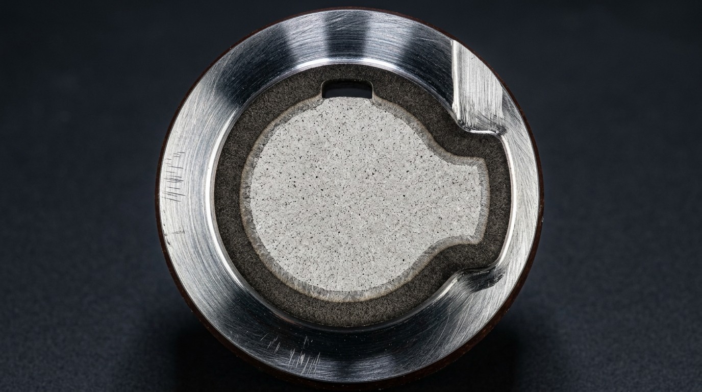
Cross-section of an induction-hardened shaft showing the clear distinction between the hardened case, the transition zone, and the core.
Machine Design Fundamentals: A Precision Mindset
Induction equipment should follow standard machine tool design practices: it must be robust, repeatable, and capable of seamless integration into cellular workflows. Many modern systems are capable of producing hundreds or even a thousand parts per hour, often utilizing robots, gantries, or conveyors for complete automation. The design must account for the rigors of continuous use, treating the induction system as a precision machine tool rather than just a "heater."
Distortion management is a constant engineering challenge. Some size or shape distortion is inevitable due to thermal expansion during heating, contraction during cooling, and phase transformations (such as the volume increase when austenite transforms to martensite). Furthermore, internal stresses from previous operations (e.g., machining or forging) are relieved during the cycle, contributing to geometry changes. However, induction surface hardening has a natural advantage: the presence of a "cold core" acts as a shape stabilizer, providing high dimensional stability, particularly on symmetrically shaped parts like axle shafts and pins.
To minimize distortion, engineers focus on distortion repeatability. If the distortion is consistent and predictable, it can be compensated for during the initial component fabrication—for instance, by slightly adjusting the green dimensions of a shaft to account for the expected growth or bowing. This requires the induction machine to maintain extremely tight control over process variables such as rotational speed, centering, and quench temperature consistency.
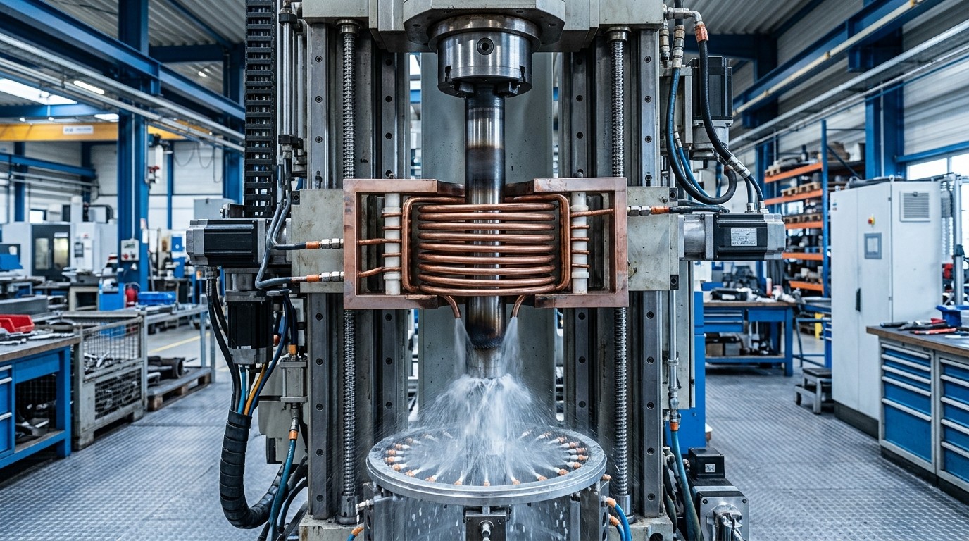
A precision vertical scanning machine showing the multi-turn coil and integrated quench system in a robust industrial housing.
Selecting the Right Hardening Method
The choice of hardening method—scan, static, or single-shot—is dictated by part geometry, production requirements, and inductor design. Each method offers specific advantages for different applications.
The Scanning Protocol: Tuning the Process Recipe
A successful scan operation relies on a precise "process recipe" involving several tunable parameters. Assuming the frequency and power levels have been properly matched to the power supply, the following "knobs" control the final metallurgical results:
- Scan Rate: This is the primary controller for case depth. A slower scan rate increases the time at heat, allowing for deeper heat penetration through thermal conduction. However, if the rate is too slow, the part may cool below the critical temperature before reaching the quench, risking the formation of upper transformation products like bainite or pearlite.
- Quench Delay: The time between heating and the application of the quenchant. This can range from a fraction of a second to several seconds. Precise control is needed to obtain adequate thermal conditions, particularly in fillets or undercuts where heat sink effects are more pronounced.
- Dwell or Soak Stage: A short time delay (often 0.5 to 2.5 seconds) where coil power is switched off or dramatically reduced before quenching. This stage is critical for improving radial temperature distribution and reducing thermal shock, especially in high-carbon steels or brittle materials like cast irons.
- Power and Frequency: These must be load-matched to ensure maximum efficiency. Higher frequencies result in shallower current penetration (skin depth), while lower frequencies enable more in-depth heating. Tuning these involves balancing voltage, frequency, and current to avoid reaching the operational limits of the power supply.
Interactions Between Scan Speed, Power, and Quench Positioning
The relationship between scan speed, power, and quench positioning is highly non-linear. To increase case depth, one might decrease scan speed or increase power. However, increasing power density too much can lead to surface overheating and grain growth. Conversely, decreasing scan speed increases the preheating effect in front of the coil through thermal conduction, which can cause the pattern to spread axially in an uncontrolled manner.
Quench positioning (the distance from the inductor face to the quench spray impingement) must be tightly coupled with scan speed. If the scan rate is increased to meet production targets, the quench distance may need to be reduced to ensure the austenitized surface is struck by the quenchant before it cools below the transformation temperature. This is where Machined Integral Quench (MIQ) designs excel, as they fix the quench-to-coil distance, ensuring that the process recipe remains stable across different production runs.
Coil Geometry and Pattern Runout
Inductor design is a balancing act between production speed and pattern precision. A critical specification is the pattern runout (also known as pattern cutoff or axial transition zone), which refers to how sharply the hardened pattern ends along the part's axis.
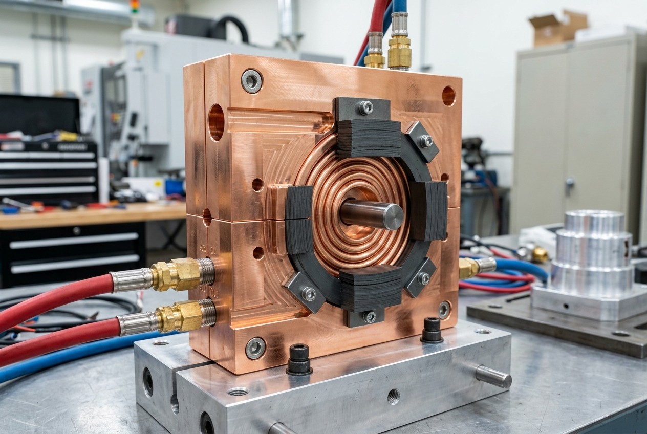
A complex CNC-machined inductor highlighting the precision engineering required for specific pattern control.
Advanced Inductor Features: MIQ and Cooling
Modern scan inductors often utilize the Machined Integral Quench (MIQ) design. In these units, the quench chamber and orifices are integrated directly into the inductor body. This ensures the quench spray impinges on the part at a precise distance (typically 12 mm to 40 mm) from the heating face, maintaining a consistent temperature window. For high-speed processes or parts with varying diameters, an additional quench follower (a separate quench barrel) may be added to prevent "tempering back," which occurs when residual heat softens the hardened case due to insufficient cooling.
In single-shot applications, where power densities are extremely high, cooling the inductor itself becomes a primary concern. Localized "squeezing" of current in specific areas (like fillets) can lead to copper overheating even with high-flow pumps. If water vaporization occurs inside the cooling pocket, it forms a steam barrier that acts as an insulator, leading to premature coil failure through cracking or arcing. Advanced designs often use multi-collar sections to split the current, reducing localized density and extending coil life significantly from standard industrial averages.
Process-Recipe Sanity Checks
Even the most sophisticated FEA models cannot account for every real-world variable. On the production floor, engineers should implement a series of concrete sanity checks to ensure the process recipe is delivering the intended metallurgical results consistently.
- Coupling Distance Consistency: Verify the air gap between the inductor and the workpiece (the coupling distance) remains constant. A change of even 0.5 mm in the air gap can lead to significant variations in power density and resulting case depth.
- Quench Delay Verification: Regularly check that the quench relay or valve response time is consistent. Electronic drift or mechanical sticking can alter the quench delay by several hundred milliseconds, which is enough to cause "soft spots" or incomplete transformation in sensitive alloys.
- Agitation and Flow Uniformity: Inspect quench orifices for clogging or scale buildup. Non-uniform quench flow leads to asymmetric cooling, which is a leading cause of part bowing and cracking. Periodic flow-meter verification for each quench circuit is essential.
- Rotation Speed Stability: Ensure the part rotation speed is high enough to even out the electromagnetic "fish-tail" effect from the coil leads, but not so high that it causes quench fluid to be thrown off the part surface by centrifugal force.
Handling Irregularities: The Role of Computer Modeling
For irregular geometries—camshafts, gears, or shafts with shoulders and cross-holes—standard recipes are rarely sufficient. Electromagnetic proximity and "end effects" can cause shoulders to overheat while neighboring fillets remain underheated. Engineers use Finite Element Analysis (FEA) computer modeling to unveil these hidden dynamics and develop complex protocols. This might include pulse heating (applying heat in short bursts with timed delays for conduction) or incorporating a power dwell to preheat fillets before the scan begins.
FAQ about Induction Hardening Machine Design
Q: What's the difference between effective case depth and total case depth?
Effective case depth measures the distance from the surface where a specific target hardness is achieved (e.g., 50 HRC or 40 HRC), based on the steel's carbon content. Total case depth includes the entire region showing any microstructural change from the core, including the transition zone where hardness gradually decreases. The transition zone is critical for residual stress distribution and fatigue performance.
Q: How do I choose between scan, static, and single-shot hardening methods?
Scan hardening is ideal for long, symmetrical parts like shafts—the inductor moves linearly while the part rotates, offering flexibility for varying lengths. Static hardening works for localized areas on complex geometries (like camshaft lobes) where movement isn't practical. Single-shot hardening heats the entire target area simultaneously, perfect for stepped shafts requiring high production rates, though it demands higher power levels.
Q: What are the key process parameters that control hardening results in scan operations?
The main tunable parameters are: scan rate (primary control for case depth—slower = deeper), quench delay (time between heating and quenching), dwell/soak stage (brief pause to improve temperature uniformity), and power/frequency (matched to desired penetration depth). These parameters interact non-linearly, so changes to one often require adjustments to others to maintain pattern quality and avoid defects.
Conclusion: Induction Hardening Machine Design
Ultimately, treating the induction system as a precision machine tool allows for "distortion repeatability." By tuning the power density, scan rate, and quench timing to the specific geometric and metallurgical requirements of the part, manufacturers can achieve the high throughput and tight tolerances demanded in modern automotive and industrial sectors. Induction surface hardening offers high-dimensional stability and repeatability, particularly on symmetrically shaped parts. The presence of a colder core acts as a shape stabilizer, ensuring that the machine delivers consistent, high-quality results across thousands of cycles.
Keep Learning
How Transparent Graphene Heaters Clear Fogged Glass
Key Takeaways Atom-thin transparency: A single graphene layer transmits about 97.7% of visible light, while five stacked layers still pass roughly 87.3%, making the heater nearly invisible on glass or plastic. Fast, controllable heating: A monolayer device reaches its target temperature with a thermal time constant of only about 6–7 seconds, and input power can be adjusted to hold temperatures from 38 °C up to around 80 °C. Efficiency advantage: Graphene heaters achieved higher temperatures at the sam......
Process Control, Monitoring, and Quality Assurance in Induction Heating: Reducing Risk Without Cutting Every Part
Key Takeaways Separate control from monitoring: A control system executes the recipe; a monitoring system independently verifies what actually happened. Independence turns logs into evidence. Monitor intermediate variables: You can't measure fatigue strength inline, but you can measure delivered kW, frequency stability, position, and quench variables—then compare each cycle to a validated "good envelope." Signature monitoring beats single thresholds: Time-series signatures capture ramps, holds, and tr......
Cooling Induction Power Supplies: Designing the Thermal System That Protects Your Electrical System
Key Takeaways Cooling is a first-class subsystem: Many "electrical" failures in induction lines are actually thermal problems—drifting water temperature, clogged filters, or unbalanced branch flow. Measure at the branch, not the header: A healthy header can mask a starved branch. Branch flow to the highest-loss modules is the single most useful cooling measurement. Trend cooling like a process variable: Baseline flow, temperature, and filter pressure drop during commissioning, then trend them to turn ......
Independent Frequency and Power Control in Induction Inverters: Turning Frequency Back Into a Process Variable
Key Takeaways Frequency as a process variable: Independent frequency and power control decouples resonance supervision from kW regulation, letting engineers set frequency based on process physics rather than control mechanics. Measurable validation: Prove independent control with three commissioning tests—fixed-frequency power steps, fixed-kW frequency sweeps, and coupling variation stability. Production consistency: Stable frequency improves recipe portability, reduces hidden process changes, and mak......
Simultaneous Dual-Frequency Induction Heating: When One Frequency Forces the Wrong Compromise
Key Takeaways One frequency, one compromise: When geometry demands both deep bulk heating and controlled surface gradients simultaneously, a single frequency forces an unacceptable trade-off—dual-frequency widens the process window. Give each channel a role: Assign the lower frequency to bulk penetration and the higher frequency to surface shaping. Structured recipe development follows naturally from this separation. Validate with metrics, not opinions: Dual-frequency is justified only when controlled......
Power Supplies by Application Family: Joining, Mass Heating, and Strip Processing
Key Takeaways Joining operations (brazing, soldering, bonding) demand higher frequencies and matching flexibility to handle variable coil coupling and precision surface heating. Mass heating lines (billets, bars, slabs) prioritize continuous duty, efficiency, and ruggedness at high power levels with multi-coil zone control. Strip processing requires architectures that separate control electronics from high-frequency inverter modules to cope with harsh installation environments. Specifying only kW and ......