
Tempering Induction-Hardened Components: Getting Toughness Back Without Losing Control
11 min
- 1. The Mechanics of Hardness and Microstructure Evolution
- 2. The Brittle Reality of Untempered Martensite
- 3. Managing Residual Stresses: Surface and Subsurface Dynamics
- 4. The Toughness Trap: Avoiding Embrittlement Zones
- 5. Induction vs. Furnace: The Parameter Shift
- 6. Implementation Strategies: Practical Approaches
- 7. Advanced Uniformity Control: The Fluxmanager Approach
- 8. The Quality Verdict: Brittle Strength and Impact Toughness
- FAQ about Tempering Induction-Hardened Components
Key Takeaways
Tempering is essential: As-quenched martensite is too brittle for service. Tempering recovers toughness and relieves residual stresses while retaining most hardness gains from induction hardening.
Avoid embrittlement zones: Tempering between 200–370°C (TME) or 450–600°C (TE) can decrease toughness despite lower hardness. Process designers must select temperatures outside these ranges.
Induction matches furnace results: Using higher temperatures with shorter hold times, induction tempering achieves equivalent metallurgical outcomes to multi-hour furnace cycles, eliminating production bottlenecks.
Stress redistribution matters: Tempering shifts dangerous subsurface tensile stress peaks deeper into the material, away from applied load zones, significantly improving fatigue life.
In the world of induction hardening, the focus is often on the dramatic transformation of the "as-quenched" state. We target high hardness and strength, but these gains come at a cost: low ductility and toughness. There is a common engineering consensus that untempered martensite is typically too brittle for most commercial applications, promoting notch sensitivity and crack development. Beyond brittleness, as-quenched martensite is characterized by high internal residual stresses that can lead to shape distortion or even delayed cracking during service.
Tempering is the critical subcritical heat treatment that follows hardening to relax these stresses and form a tempered martensite microstructure. By reheating the steel to temperatures below the lower transformation temperature (Ac1), we seek a desirable compromise—recovering toughness and ductility without sacrificing too much hardness and strength. In many modern production lines, this isn't just a metallurgical requirement; it's a process reliability necessity to prevent delayed cracking attributed to residual stress.
1. The Mechanics of Hardness and Microstructure Evolution
The primary goal of tempering is the decomposition of martensite into an alpha-iron matrix with a dispersion of carbide particles. This process occurs in several overlapping stages as the temperature increases. For most plain carbon and low-alloy steels, there is a monotonic relationship between tempering temperature and hardness: as the temperature rises, hardness and strength decrease. A typical low-temperature temper at 120°C to 250°C might only reduce hardness by 1 to 4 HRC points, providing a subtle but important boost to stability.
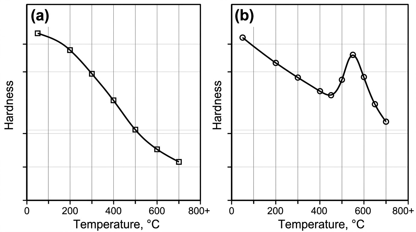
Figure 1: Comparison of hardness vs. tempering temperature for plain carbon steels (monotonic decrease) and alloy steels with carbide formers showing secondary hardening.
However, for alloy steels containing strong carbide formers like chromium, molybdenum, or vanadium, the relationship is more complex. These materials can exhibit "secondary hardening," where alloy carbides precipitate at temperatures between 500°C and 600°C, actually causing a localized increase in hardness. Furthermore, tempering plays a vital role in decomposing retained austenite (RA), which might otherwise transform into untempered martensite during the component's service life, leading to late-stage brittleness and distortion.
2. The Brittle Reality of Untempered Martensite
When a component is quenched to form martensite, the resulting structure is in a state of extreme thermodynamic instability. The carbon atoms are trapped in a body-centered tetragonal (BCT) lattice, creating immense internal strain. This strain translates to high hardness, but it also makes the material susceptible to catastrophic failure. Untempered martensite is notoriously brittle; it lacks the ability to deform plastically, meaning any stress concentration—a notch, a scratch, or a sharp corner—can act as a site for rapid crack propagation.
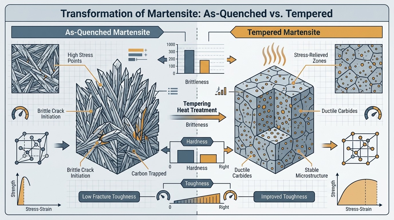
Figure 2: Infographic showing the transition from brittle as-quenched martensite to more stable tempered martensite.
Furthermore, the quenching process itself introduces high levels of internal residual stresses. These stresses are not uniform; they vary from the surface to the core, often leaving the surface in compression and the subsurface in tension. If these stresses are not relieved through tempering, they may lead to delayed cracking. This phenomenon, sometimes called "season cracking" or "quench cracking," can occur hours or even days after the part has been cooled to room temperature. The probability of delayed cracking depends on several factors: the hardness level, the specific case pattern, the chemical composition of the alloy, and the overall geometry of the part.
For components made of medium-carbon steels, high-carbon steels, and certain cast irons, there is also the issue of Retained Austenite (RA). In the as-quenched state, a portion of the austenite may fail to transform into martensite. This RA is unstable and can transform into untempered martensite during the component's service life, leading to dimensional instability and late-stage brittleness. Tempering provides the thermal energy necessary to decompose this retained austenite into more stable phases, ensuring the long-term integrity of the component.
Risks of Untempered Structures
- High internal residual stresses causing shape distortion during service life.
- Notch sensitivity promoting rapid crack development under applied loads.
- Potential for delayed cracking hours or days after the quenching operation.
- Dimensional instability due to the late-stage transformation of retained austenite.
3. Managing Residual Stresses: Surface and Subsurface Dynamics
A common misconception in heat treating is that low-temperature tempering removes all internal residual stresses. In reality, it relaxes only a portion of them. More importantly, tempering shifts the distribution of these stresses. In surface-hardened components, the quenching process typically leaves the maximum tensile residual stress just beneath the hardened case or within the hardness transition zone. This subsurface region is a primary site for crack initiation under service loads.
One of the most critical "duties" of tempering is to shift this maximum tensile stress peak further toward the core, away from the surface where applied service loads (such as bending or torsion) are usually highest. By reducing the magnitude of these tensile stresses and moving them deeper into the material, we significantly improve the fatigue life and performance of the part. Even a subtle low-temperature temper can provide enough stress relaxation to prevent delayed cracking without substantially sacrificing the wear resistance provided by high surface hardness.
4. The Toughness Trap: Avoiding Embrittlement Zones
While engineers generally expect toughness to improve as hardness decreases during tempering, the progression is not always linear. There are specific "embrittlement zones" where impact toughness can actually drop, despite a decrease in hardness. Understanding these valleys is vital for process design. A recipe that works for a part in pure tension may not provide the same benefits for a part subjected to torsion or bending.
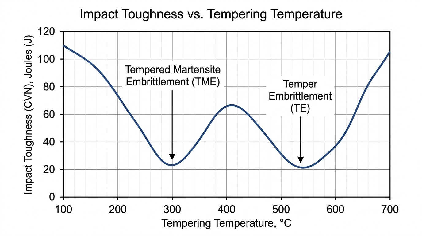
Figure 3: Impact toughness as a function of tempering temperature, highlighting the critical embrittlement valleys.
Tempered Martensite Embrittlement (TME) typically occurs when a part is tempered within the range of 200°C to 370°C. This is an irreversible phenomenon; once TME occurs, the only way to recover toughness is to re-austenitize and quench the part again. In contrast, Temper Embrittlement (TE) appears at higher temperatures, generally between 450°C and 600°C. Unlike TME, temper embrittlement is a reversible phenomenon that can sometimes be mitigated by specific cooling rates or subsequent heat treatment cycles.
5. Induction vs. Furnace: The Parameter Shift
Traditional furnace tempering is a time-intensive process. Because furnaces rely on convection and radiation to heat a batch of parts, it often takes 1 to 3 hours to achieve thermal equilibrium and complete the necessary diffusion-based transformations. In modern lean manufacturing, this creates a significant bottleneck that induction tempering aims to resolve.
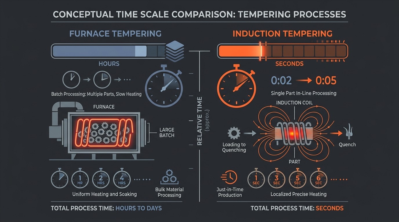
Figure 4: Conceptual comparison of processing times between furnace and in-line induction tempering.
Induction tempering offers a high-speed alternative by leveraging electromagnetic heating to reach target temperatures in seconds or tens of seconds. However, this speed requires a shift in parameters. Because tempering is a diffusion-driven process, it is a function of both time and temperature. To achieve the same metallurgical results and hardness as a long-soak furnace cycle, induction tempering must utilize higher temperatures.
The Larsen-Miller Parameter in Practice
Hardness is modeled as a function of: $P = T \times [C + \log_{10}(t)]$
T: Absolute tempering temperature (K).
t: Time at temperature (hours).
C: Alloy-dependent constant (typically between 10 and 18 for steels).
This relationship enables "short-time, high-temperature" cycles that match the throughput of in-line induction hardening machines.
6. Implementation Strategies: Practical Approaches
There are three primary ways to implement tempering in a production environment, each offering unique benefits and facing specific constraints.
1Self-Tempering (Slack Quenching)
Utilizing residual heat retained in the core of the part after a partial quench. As the quench is cut off, heat flows from the core back to the surface, raising its temperature into the tempering range (typically 180°C to 220°C for automotive components).
2Induction Tempering
Reheating the hardened part via electromagnetic induction. This offers precise controllability and the ability to selectively temper specific regions of a complex part.
3Furnace/Oven Tempering
The traditional batch or continuous convection process. Reliable but consumes significant floor space and energy.
Self-tempering is highly energy-efficient and eliminates time delays, but it requires extreme precision in quench control and is generally limited to simple geometries like straight shafts. Large workpieces with a cold core may also provide too much of a heat sink effect, preventing the necessary temperature rise. For complex parts, dedicated induction tempering coils are the preferred choice. These coils are typically designed with loose coupling and lower frequencies than their hardening counterparts to ensure gentle, uniform heating. Unlike hardening, tempering temperatures are always below the Curie point, meaning the steel remains magnetic and the skin effect is highly pronounced.
7. Advanced Uniformity Control: The Fluxmanager Approach
When tempering thick-walled tubular goods or complex shafts, achieving radial and longitudinal uniformity is the ultimate challenge. Conventional high-frequency induction can lead to "skin" heating where the surface overheats before the interior reaches the target temperature. This radial temperature nonuniformity can result in undesirable heterogeneous stress-relieving properties.
Figure 5: Advanced coil design concepts used to optimize longitudinal temperature uniformity.
Technologies like Fluxmanager address this by utilizing line frequencies (50-60 Hz) for deeper penetration. By combining these low frequencies with proprietary magnetic flux concentrators, energy can be focused exactly where it's needed—compensating for "cold sinks" in mass-heavy regions and preventing "hot spots" at edges or thin sections. This level of control is what makes in-line induction tempering a robust, high-quality alternative to massive furnace setups, ensuring superior repeatability and quality.
8. The Quality Verdict: Brittle Strength and Impact Toughness
The ultimate proof of any production process is field performance. While some metallurgists may still lean toward long-soak furnace cycles, research shows that induction tempering can provide equal, and sometimes superior, brittle strength and impact toughness. For example, studies have shown that tempered carbon steel parts subjected to higher-temperature, shorter-time induction tempering can exhibit up to three times higher brittle strength compared to parts tempered for hours at lower temperatures, provided the hardness is identical.
When done correctly, the slight reduction in hardness is more than offset by the benefits obtained: internal stress relief, improved ductility or toughness, shifting of the dangerous maximum of tensile stresses farther away from the applied stresses, and improved machinability. Masterful control over the "toughness recovery" phase is just as important as the hardening itself. Mastering these techniques allows the modern engineer to prevent delayed cracking, improve fatigue life, and optimize the overall performance of induction-hardened components.
FAQ about Tempering Induction-Hardened Components
Q: Why can't we use induction-hardened parts without tempering?
Untempered martensite is extremely brittle and contains high internal residual stresses. This makes parts prone to catastrophic failure at stress concentrations and can cause delayed cracking hours or days after quenching. Tempering recovers toughness and relieves these dangerous stresses while maintaining most of the hardness gained during hardening.
Q: How does induction tempering achieve the same results as furnace tempering in much less time?
Tempering is governed by the Larsen-Miller Parameter, which shows that hardness depends on both temperature and time. Induction tempering uses higher temperatures (with electromagnetic heating reaching target temps in seconds) to compensate for the shorter time, achieving equivalent metallurgical transformations that would take 1-3 hours in a furnace.
Q: What is the "embrittlement zone" and why does it matter?
The embrittlement zone refers to specific temperature ranges (200-370°C for TME, 450-600°C for TE) where impact toughness actually decreases despite reduced hardness. Tempering within these ranges can make parts more brittle rather than tougher. Process designers must carefully select tempering temperatures outside these zones to ensure optimal toughness recovery.
Conclusion: Tempering Induction-Hardened Components
The slight reduction in hardness from tempering is more than offset by internal stress relief, improved ductility and toughness, shifting of dangerous tensile stress peaks away from applied load zones, and improved machinability. Masterful control over the toughness recovery phase—whether through self-tempering, induction, or furnace methods—allows the modern engineer to prevent delayed cracking, improve fatigue life, and optimize the overall performance of induction-hardened components.
Keep Learning
How Transparent Graphene Heaters Clear Fogged Glass
Key Takeaways Atom-thin transparency: A single graphene layer transmits about 97.7% of visible light, while five stacked layers still pass roughly 87.3%, making the heater nearly invisible on glass or plastic. Fast, controllable heating: A monolayer device reaches its target temperature with a thermal time constant of only about 6–7 seconds, and input power can be adjusted to hold temperatures from 38 °C up to around 80 °C. Efficiency advantage: Graphene heaters achieved higher temperatures at the sam......
Process Control, Monitoring, and Quality Assurance in Induction Heating: Reducing Risk Without Cutting Every Part
Key Takeaways Separate control from monitoring: A control system executes the recipe; a monitoring system independently verifies what actually happened. Independence turns logs into evidence. Monitor intermediate variables: You can't measure fatigue strength inline, but you can measure delivered kW, frequency stability, position, and quench variables—then compare each cycle to a validated "good envelope." Signature monitoring beats single thresholds: Time-series signatures capture ramps, holds, and tr......
Cooling Induction Power Supplies: Designing the Thermal System That Protects Your Electrical System
Key Takeaways Cooling is a first-class subsystem: Many "electrical" failures in induction lines are actually thermal problems—drifting water temperature, clogged filters, or unbalanced branch flow. Measure at the branch, not the header: A healthy header can mask a starved branch. Branch flow to the highest-loss modules is the single most useful cooling measurement. Trend cooling like a process variable: Baseline flow, temperature, and filter pressure drop during commissioning, then trend them to turn ......
Independent Frequency and Power Control in Induction Inverters: Turning Frequency Back Into a Process Variable
Key Takeaways Frequency as a process variable: Independent frequency and power control decouples resonance supervision from kW regulation, letting engineers set frequency based on process physics rather than control mechanics. Measurable validation: Prove independent control with three commissioning tests—fixed-frequency power steps, fixed-kW frequency sweeps, and coupling variation stability. Production consistency: Stable frequency improves recipe portability, reduces hidden process changes, and mak......
Simultaneous Dual-Frequency Induction Heating: When One Frequency Forces the Wrong Compromise
Key Takeaways One frequency, one compromise: When geometry demands both deep bulk heating and controlled surface gradients simultaneously, a single frequency forces an unacceptable trade-off—dual-frequency widens the process window. Give each channel a role: Assign the lower frequency to bulk penetration and the higher frequency to surface shaping. Structured recipe development follows naturally from this separation. Validate with metrics, not opinions: Dual-frequency is justified only when controlled......
Power Supplies by Application Family: Joining, Mass Heating, and Strip Processing
Key Takeaways Joining operations (brazing, soldering, bonding) demand higher frequencies and matching flexibility to handle variable coil coupling and precision surface heating. Mass heating lines (billets, bars, slabs) prioritize continuous duty, efficiency, and ruggedness at high power levels with multi-coil zone control. Strip processing requires architectures that separate control electronics from high-frequency inverter modules to cope with harsh installation environments. Specifying only kW and ......