
Hardening Complex Geometries: Holes, Keyways, Grooves—and Managing Distortion and Cracking
11 min
- The Physics of Geometrical Pitfalls
- The Balancing Act: Distortion Control
- Root Causes of Cracking: The Seven Main Categories
- Practical Mitigation Strategies
- FAQ about Hardening Complex Geometries
Key Takeaways
Geometrical Irregularities Disrupt Eddy Currents: Holes, keyways, and grooves force eddy currents to redistribute, creating hot spots and cold spots that lead to distortion and cracking if not managed properly.
Distortion is a Process Chain Issue: Excessive warpage stems from accumulated factors—part geometry, material condition, inductor design, heating parameters, quench uniformity, and fixturing all contribute.
Cracking Has Seven Root Causes: Material defects, geometry stress risers, overheating, quench problems, inductor design, tooling issues, and process delays (especially delayed tempering) are the primary culprits.
Precision Energy Management is Key: Successful hardening of complex parts requires inductor profiling, plug techniques, stress relieving, and uniform quenching—not brute-force heating.
In the world of induction hardening, "simple" is a luxury that few modern engineering components provide. Real-world parts—from transmission shafts and crankshafts to engine gears and ball bearing cages—are rarely uniform cylinders. Instead, they are defined by their necessary irregularities: longitudinal and transverse holes, keyways, snap ring grooves, splines, and sharp corners. For an induction practitioner, these geometrical discontinuities are not just design features; they are significant eddy current disruptors. If not managed with precision, they become primary drivers for non-uniform heating, excessive shape distortion, and catastrophic cracking during the heating or quenching cycles.
The presence of these discontinuities fundamentally alters the path of induced eddy currents, forcing them to divert around obstacles or squeeze into narrow channels. This diversion leads to the undesirable appearance of "hot spots" (heat surplus) and "cold spots" (heat deficit). Severe overheating is the most frequent culprit, often resulting in metallurgical damage such as grain boundary liquation. This structural weakening substantially increases the material's brittleness and its sensitivity to intergranular cracking, turning a critical engineering component into a potential failure point before it even leaves the production floor.
The Physics of Geometrical Pitfalls
When eddy currents encounter a hole or a groove, they cannot simply pass through the empty space. They must find an alternative path through the surrounding metal. This redistribution is governed by the principles of electromagnetics and thermal conduction. The resulting non-uniformity is not just a surface phenomenon; it extends into the depth of the part, influenced by the current penetration depth (δ).
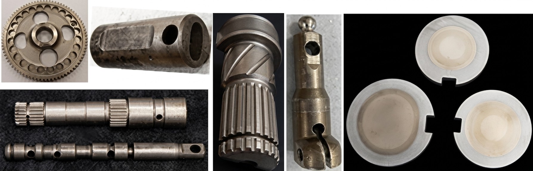
Figure 1: Typical industrial components featuring complex geometrical irregularities that disrupt eddy current flow.
Longitudinal vs. Transverse Holes
The impact of a hole depends largely on its orientation relative to the inductor and its proximity to the heated surface. Longitudinal (axial) holes, which run parallel to the axis of the part, can cause a significant redistribution of eddy current flow by "squeezing" the current into a narrow channel between the part surface and the hole wall. This dramatically increases current density in that narrow ligament, leading to severe local overheating.
There are two primary factors that drive overheating in the vicinity of longitudinal holes:
- Electromagnetic Redistribution: An increase in local heat source generation occurs because the eddy current path is partially blocked, forcing a higher concentration of current into the remaining metal path.
- The "Cold Sink" Effect: The lack of an adjacent mass of metal means there is reduced heat transfer from the hot surface toward the colder core. Without enough metal to act as a thermal sink, the temperature surplus in the surface layer cannot be effectively dissipated.
The dominance of these factors depends on the hole's depth. If a hole is located within the current penetration depth (δ), the electromagnetic redistribution is the primary cause of overheating. If the hole is deeper—located 1 to 2 times δ from the surface—both factors contribute roughly equally to the heat surplus. When the hole is located 2 to 3 times δ away, the lack of adjacent mass becomes the dominant factor, especially during longer heating cycles (8–12 seconds). Beyond 3δ, the probability of the hole affecting the surface heating pattern is typically slim.
Transverse (radial) holes present a different and often more complex challenge. Unlike longitudinal holes, they always cause a redistribution that results in both overheating and underheating. Due to current concentration, hot spots occur at the hole edges parallel to the eddy current flow. Conversely, a heat deficit (cold spot) occurs at the edges perpendicular to the current flow. If the hole diameter is less than half of δ, the distortion is typically manageable. However, as the diameter increases, the non-uniformity becomes more pronounced, increasing the risk of grain boundary liquation and complex transient stress distributions.
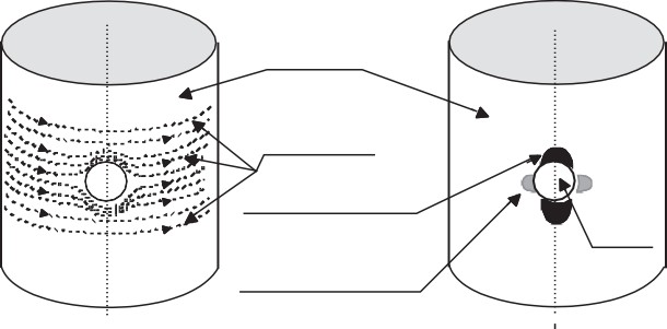
Figure 2: Diversion of eddy current flow lines and resulting heat concentration zones around a transverse hole.
Keyways, Grooves, and Snap Rings
Keyways and snap ring grooves are essentially extreme cases of geometrical irregularities. Keyways can be viewed as large-scale longitudinal holes that break the surface. Their size, shape, and orientation relative to the inductor have a substantial impact on the resulting temperature profile. Common issues include severe overheating of sharp corners and significant underheating at the bottom of the groove. Snap ring grooves require even more caution; if only half the groove is hardened, it can create a highly undesirable transient and residual stress distribution within the groove area, often leading to failure.
Angled Holes and Geometrical Stress Risers
Angled holes, such as oil holes in crankshafts, are particularly susceptible to cracking. A sharper angle results in more pronounced overheating and non-uniform case depth, as the heating combines the problematic features of both longitudinal and transverse orientations. Furthermore, these regions exhibit varied cooling intensities during quenching. In conventional designs, the acute angle area experiences much more severe cooling intensity, which complements the heat surplus from the heating cycle and heightens crack sensitivity significantly.
Beyond the macro-geometry, micro-defects act as measurable stress risers. Folds, burrs, machine marks, and deep scratches provide nucleation sites for crack initiation. It is essential that holes are generously chamfered and have smooth surfaces. Rough machined surfaces, excessive chattering, or the presence of coarse inclusions can provide a preferential path for crack propagation. In fact, inappropriate chamfering should be strictly avoided as it can trigger crack development rather than preventing it.
The Balancing Act: Distortion Control
Induction hardening is a constant compromise between three competing goals: achieving the required hardness and strength, maintaining a tough structure with beneficial residual stresses, and producing components with minimal distortion. Excessive distortion is rarely the result of a single error; it is usually an accumulation of factors across the entire process chain, from the initial manufacturing steps to the final quenching parameters.
Critical Drivers of Distortion
When troubleshooting distortion, engineers must evaluate several primary factors that influence the final shape and size of the component:
- Component Geometry: Complexity, unbalanced mass, and sharp transitions between sections.
- Material: Chemical composition, prior microstructure (e.g., Q&T vs. normalized), and initial "hidden" stresses from forging or casting.
- Inductor Design: Profiling accuracy, electromagnetic coupling (air gap) uniformity, and coil impedance.
- Process Parameters: Peak temperatures, heating times, and applied frequencies. Excessive heat generation is a major driver of metal expansion/contraction.
- Quenching: Uniformity of quench flow, pressure, temperature, and concentration. Non-uniform quenching is a common cause of the "banana effect" (warpage).
- Tooling and Fixtures: Support stability, rotation accuracy (avoiding wobbling), and ensuring parts don't fit too snugly, allowing "room to grow" during thermal expansion.
Root Causes of Cracking: The Seven Main Categories
Cracking is the ultimate failure of the hardening process. The causes are often interrelated, but they can be categorized into seven distinct groups to facilitate systematic failure analysis and prevention:
- Material Related: Nonhomogeneous structures, severe segregation, excessive inclusions, or high carbon/sulfur/phosphorus content. Sulfur produces brittle iron sulfides (FeS) at grain boundaries, which can lead to liquation.
- Workpiece Geometry: Sharp edges, shoulders, poor chamfers/roundings, and the location, orientation, and size of irregularities like grooves and holes.
- Power/Energy Cycle: Overheating, excessive heating time, or higher-order harmonics causing localized hot spots. Burns from sparks or field fluctuations can also be factors.
- Quenching Conditions: Non-uniformity, improper quenchant type, contaminated fluids, or excessive quench severity (flow rate and pressure).
- Inductor Design: Inadequate coil geometry, improper flux concentrator placement, or coil impedance issues that fail to address geometrical features.
- Tooling and Accessories: Improper part positioning, excessive wobbling, part slippage, or fixtures that apply unwanted mechanical force or prevent expansion.
- Other Factors: Decarburization (which can reverse surface stress to tension), grain boundary liquation, or excessive delays between hardening and tempering (leading to delayed cracking).
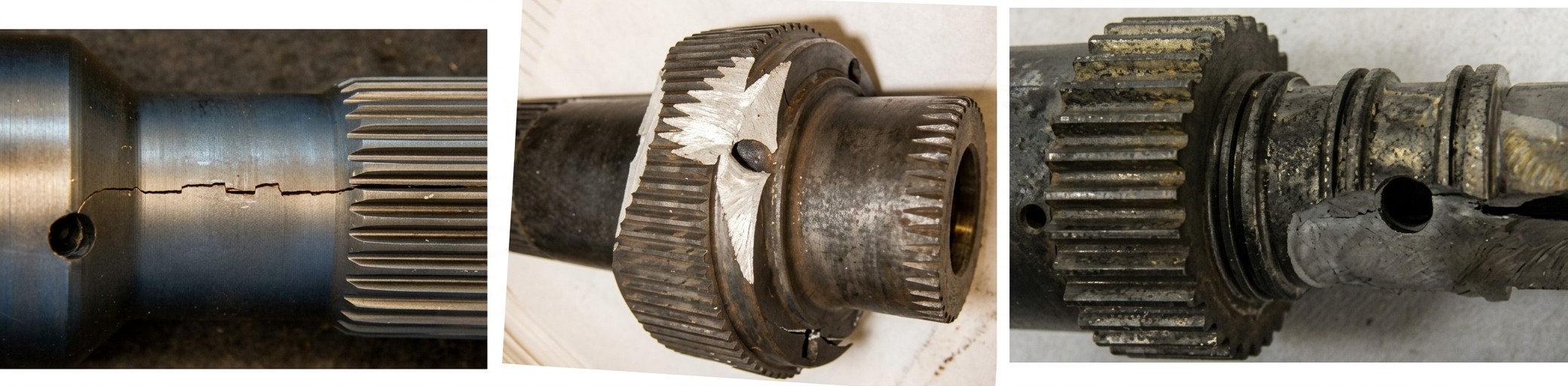
Figure 3: Examples of failures initiated at geometrical discontinuities, including longitudinal cracks at oil holes and gear fracture.
Practical Mitigation Strategies
Successfully hardening complex parts requires a move away from "brute force" heating toward precise energy management. Advanced techniques and practical solutions include:
- Inductor Profiling: Modifying the copper geometry to provide "preferable channels" for eddy current flow, effectively steering the heat away from sensitive hole edges and corners. Profiling can selectively control heat distribution along a hole's perimeter.
- Use of Plugs: Steel or copper plugs can be used as a last resort to equalize heating. Steel plugs (of the same alloy) make non-uniformities negligible but can weld in place. Copper plugs are often preferred because their low electrical resistivity draws current away from steel edges, while their high thermal conductivity helps dissipate heat surplus. Water-soaked wooden plugs can also reduce overheating via thermal conduction.
- Stress Relieving: Performing a pre-hardening stress relief at 550°C–650°C (1050°F–1200°F) for 1.5–2 hours. This establishes a stable geometric baseline and eliminates "hidden" stresses from machining or forging that might otherwise cause unexpected movement during heating.
- Quench Uniformity: Using properly designed quench systems that address gravity and "bouncing" effects. Ensuring that every surface area receives equal cooling intensity is critical to avoiding warpage and cracking.
Practical Troubleshooting Flow
When distortion or cracking occurs unexpectedly, engineers should follow a grounded troubleshooting sequence based on industrial best practices:
-
Verify Baseline Stresses
Measure "green" parts and perform stress relief at 600°C to see if distortion originates from previous manufacturing steps (forging/casting).
-
Audit Chemical Composition
Check sulfur and phosphorus levels. Sudden cracking is often tied to a change in steel supplier or an unfavorable combination of residual impurities.
-
Inspect Tooling & Positioning
Check for excessive wobbling or tilting during rotation. Ensure fixtures allow for thermal growth without applying excessive mechanical force.
-
Evaluate Quench Integrity
Check for plugged quench orifices, contaminated fluids, or deviations in pressure and flow. Recorded "runout" parameters must be strictly maintained.
-
Optimize the Heat Cycle
If overheating is present, consider increasing frequency (for shallower penetration) or reducing power density/heating time to minimize the mass of heated metal.
The "Tempering Delay" Warning
A common but avoidable cause of cracking is excessive time between quenching and tempering. Untempered martensite is highly brittle. Long delays, especially in cold environments or with low-toughness materials like high-carbon steels and cast irons, can lead to delayed cracking as internal stresses continue to evolve. Best practice dictates that tempering should occur immediately after hardening, ideally within the same production line or building, to prevent parts from continuing to "quench" in cold ambient conditions.
FAQ about Hardening Complex Geometries
Q: Why do holes cause problems during induction hardening?
Holes disrupt eddy current flow, forcing currents to redistribute around them. This creates hot spots (overheating) and cold spots (underheating). Longitudinal holes squeeze current into narrow channels, while transverse holes cause both overheating at edges parallel to current flow and underheating at perpendicular edges. The severity depends on hole size, orientation, and distance from the surface relative to the current penetration depth (δ).
Q: What are the main causes of cracking in hardened parts with complex geometries?
Cracking typically results from seven categories: material issues (segregation, high sulfur/phosphorus), poor geometry (sharp edges, inadequate chamfers), overheating during the power cycle, non-uniform quenching, improper inductor design, faulty tooling/fixtures, and process delays. A critical mistake is delaying tempering after quenching—untempered martensite is extremely brittle and prone to delayed cracking.
Q: How can distortion and cracking be prevented when hardening parts with keyways or grooves?
Key strategies include: profiling the inductor to steer heat away from sensitive areas, using copper or steel plugs to equalize heating, performing pre-hardening stress relief (550–650°C), ensuring uniform quench flow across all surfaces, and allowing fixtures to accommodate thermal expansion. Avoid overheating by optimizing frequency and power density, and always temper immediately after quenching.
Conclusion: Mastering Complex Geometry Hardening
Ultimately, achieving a "locked in place" hardness pattern with straightness tolerances in the range of 3–5 microns—often eliminating post-hardening straightening—requires total process control. By minimizing peak temperatures, ensuring uniform quenching, and avoiding any external force during the cycle, modern induction systems can successfully master the complexities of real-world geometrical irregularities.
Keep Learning
Simultaneous Dual-Frequency Induction Heating: When One Frequency Forces the Wrong Compromise
Key Takeaways One frequency, one compromise: When geometry demands both deep bulk heating and controlled surface gradients simultaneously, a single frequency forces an unacceptable trade-off—dual-frequency widens the process window. Give each channel a role: Assign the lower frequency to bulk penetration and the higher frequency to surface shaping. Structured recipe development follows naturally from this separation. Validate with metrics, not opinions: Dual-frequency is justified only when controlled......
Power Supplies by Application Family: Joining, Mass Heating, and Strip Processing
Key Takeaways Joining operations (brazing, soldering, bonding) demand higher frequencies and matching flexibility to handle variable coil coupling and precision surface heating. Mass heating lines (billets, bars, slabs) prioritize continuous duty, efficiency, and ruggedness at high power levels with multi-coil zone control. Strip processing requires architectures that separate control electronics from high-frequency inverter modules to cope with harsh installation environments. Specifying only kW and ......
Simultaneous Dual-Frequency Induction Power: When One Frequency Forces the Wrong Compromise
Key Takeaways Dual-frequency is justified by robustness, not complexity: It should only be adopted when a single frequency forces an unacceptable compromise between surface and bulk heating requirements. Give each frequency a defined role: Assign the lower frequency to bulk heating/penetration and the higher frequency to surface shaping—then develop recipes one variable at a time. The combining network is the engineering center of gravity: Frequency-selective coupling paths, thermal rating for worst-c......
Applying Induction Power Supplies in the Real World: Constraints That Decide Uptime and Quality
Key Takeaways Application constraints dominate real-world performance: Two induction systems with identical kW ratings can behave very differently depending on cable length, cooling water temperature, dust levels, and fixture repeatability. Design for drift, not for perfect day one: Coils deform, filters clog, sensors drift, and connectors loosen under thermal cycling. Baseline monitoring during commissioning is essential. Mechanical repeatability often beats control complexity: Improving fixturing an......
Medium- and High-Frequency Transformers in Induction Systems: Design Drivers Engineers Should Actually Care About
Key Takeaways Not Passive: Transformers set the electrical operating point for the entire induction station—coil voltage, current, capacitor stress, and inverter margin all depend on transformer choice. Frequency Effects: At higher frequencies, winding losses and stray capacitance dominate; a transformer that looks fine on turns ratio can fail a duty-cycle test if loss distribution is wrong. Placement Matters: Moving the transformer and capacitor bank closer to the coil reduces high-frequency loop len......
Load Matching in Induction Heating: Designing for Stability, Efficiency, and Real-World Variation
Key Takeaways Dynamic Load: Induction heating loads are not fixed—coupling, material properties, and temperature all shift impedance during operation, making matching a continuous design challenge. Q Factor Matters: High-Q loads can produce large circulating currents and capacitor stress even at modest delivered kW; design for the worst-case kVA, not just power. Discrete Ranges Win: Transformer taps and capacitor steps that cover discrete matching ranges outperform a single broad-range configuration f......