
Keeping Induction Heat Treating Equipment Healthy: Maintenance Practices That Prevent Downtime
12 min
- 1. The Core Pillars of Induction Maintenance
- 2. Preventive Maintenance Checklist: A Structured Cadence
- FAQ about Induction Heat Treating Equipment Maintenance
Key Takeaways
Preventive maintenance reduces costly downtime, extends induction equipment service life, and ensures consistent part quality — transitioning from "fix-it-when-it-breaks" to proactive care.
Six critical subsystems demand routine attention: power supply, heat station, water recirculating system, quench recirculating system, heating coils (inductors), and mechanical machinery.
Thermal imaging (IR cameras) combined with visual and audible inspection are the most effective tools for detecting hot spots, arcing, and abnormal operation before failure occurs.
Follow a structured cadence: daily shift-startup checks, weekly cleaning and alignment, monthly/quarterly deep inspections including torque verification and thermal scans.
Treat inductors as high-value assets: proper cleaning with mild soap and plastic brushes, regular crack inspection, and flux concentrator checks prevent the most common failure points.
1. The Core Pillars of Induction Maintenance
Maintenance for induction heat treating can be categorized into six primary areas: the power supply, heat station, water recirculating system, quench recirculating system, heating coils (inductors), and the mechanical machinery itself. Before any maintenance activity begins, safety must be the absolute priority. All power must be turned off, and equipment should be safely discharged before inspection. The three primary senses—vision, smell, and hearing—are the most effective tools for identifying abnormal operation or deterioration before a catastrophic failure occurs.
The Impact of Effective PM
- Repeatability: Consistent component condition ensures stable process parameters and part quality.
- Asset Longevity: Prevents premature wear of expensive copper inductors and power semiconductors.
- Operational Safety: Early detection of arcing and leaks reduces the risk of equipment fires or electrical hazards.
Power Supply and Electrical Integrity
Dust, moisture, and localized "hot" spots are the most frequent causes of failure in electrical and electronic devices. A thorough visual inspection is the first line of defense. Engineers should look for signs of overheating, arcing, mechanical deformation, or condensation on control boards and power connections. All electrical insulators, such as capacitor bushings and bus insulators, must be wiped clean to a "like-new" condition to prevent tracking. Tracking occurs when dirt or carbon forms a conductive path across an insulator, eventually leading to a high-energy arc-over that can destroy expensive components.
Within the cabinet, attention should be paid to the condition of the copper tube on the positive side of DC bus cooling connections. A common failure mode in systems with DC links is electrolysis. If cooling hoses are too short, electrical current can flow through the water itself, eating away at the positive bus cooling tube and depositing the copper on the negative tube. This "sacrificial" behavior can lead to pinhole leaks in the buswork. On high-voltage vacuum tube systems, a sacrificial anode is often intentionally included to protect the fitting; this anode must be replaced periodically as it degrades.
Thermal imaging has become an essential method for inspecting electrical circuits. Infrared cameras can pinpoint poor connections and hot spots on bus networks, cables, and components that are invisible to the naked eye. For instance, a thermal scan might reveal an alarmingly high temperature at a loose bolt connection between a cable and a bus bar, signaling an imminent failure point. Thermal imaging should be performed both during operation (with doors closed via IR windows) and immediately after shutdown to identify components that are retaining heat abnormally.
Mechanical tests are equally critical; engineers must verify the tightness of all control and power connections, capacitor hardware, and transformer tapping hardware. Using a signal generator or load frequency analyzer to determine the resonant frequency of the power and load circuit can also provide a baseline for system health. Changes in resonant frequency over time often indicate degradation in the capacitor bank or shifts in the induction coil's geometry. During operation, listen for "ticking" sounds, which often indicate electrical arcing or the breakdown of a component's dielectric strength.
Maintaining Heat Stations and Bus Connections
The heat station and buswork are subject to high voltages and currents, making them prone to arcing if not properly maintained. Arcing is often caused by insufficient torque on bolts holding the buswork or a breakdown of insulation. Any carbon tracks generated by arcing must be thoroughly cleaned and repaired; otherwise, the carbon will facilitate repeated failures in the same area. Inductor terminals and quick-disconnect devices must be checked for flatness and kept free of dust, oil, and debris. Any nicks, burrs, or scratches on these contact surfaces will redistribute current density, creating localized hot spots and further arcing.
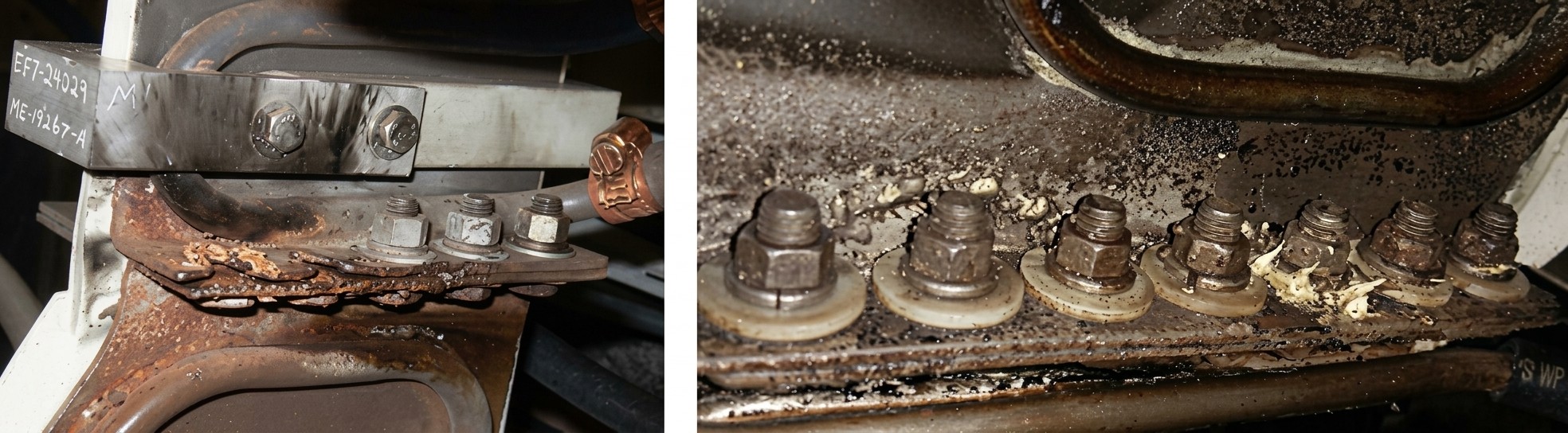
Corroded and overheated electrical connections illustrating the severe damage caused by environmental contaminants and loose fasteners.
Fastener choice is critical in the vicinity of the inductor. To avoid electromagnetic overheating, nonferrous materials like silicon bronze or nonmagnetic stainless steels must be used for bolts and washers. Stainless steel bolts (typically 10mm to 12mm) should be tightened to approximately 40 to 45 lbf/ft. Overtightening can strip threads from the soft copper bus, while undertightening leads to high resistance and arcing. In specific low-stress or high-corrosion environments, ceramic or polymer fasteners may be utilized. Ceramic fasteners are immune to induction heating and can withstand temperatures exceeding 1000°C, but they are extremely brittle and prone to fracture if overtightened.
As a general rule, ferrous materials should be located at least one coil diameter away from the inductor to prevent parasitic heating. If ferrous components must be used closer, they should be shielded or designed with geometries that minimize eddy current losses. Ground fault detectors are another essential safety circuit in the heat station. These circuits detect if the workpiece or an operator makes contact with the energized coil. It is a dangerous practice to reduce the sensitivity of a ground fault detector to stop "nuisance" trips; instead, the root cause—such as moisture buildup or shifted flux concentrators—must be addressed.
Water and Quench Fluid Systems
Fluid systems require constant monitoring of flow, pressure, and chemistry. Water leaks, clogged hoses, and algae growth in tanks can quickly lead to overheating. Conductivity is a critical parameter for cooling water; high conductivity can lead to electrolysis, especially in systems with DC links. A typical maintenance target is to keep water at 10 μSiemens/cm and change it when it reaches 100 μSiemens/cm. On systems without a DC link, a level of 400 μSiemens/cm may be acceptable. The quality of city or well water is typically inappropriate for these systems due to mineral content that can form scale inside cooling passages.
Freeze protection is vital for equipment located in cold climates. Only use propylene glycol or low-conductivity ethylene glycol as specified by the OEM. Standard automotive antifreeze is not suitable due to its high conductivity and potential to damage gaskets. If a system is not properly protected, the freezing of water in thin-wall copper tubes can rupture the tubes, leading to internal leaks that are exceptionally difficult to locate. Additionally, air trapped in closed systems can cause air locks, reducing cooling efficiency and leading to cavitation in pumps.
The quench system faces additional challenges from scale flakes and oil contamination. Scale flakes from heat-treated parts are highly abrasive and can clog spray quench holes, causing inconsistent hardness patterns. Metallic scale can also deposit on bus edges, creating bridges that lead to arcing. Regular concentration checks with a refractometer are necessary to ensure the cooling rate remains within specification. Oil from the workpiece or hydraulic leaks can lead to excessive foaming and irregular cooling. Quench tanks should be covered to prevent environmental contamination, and biological growth should be monitored via odor and appearance checks.
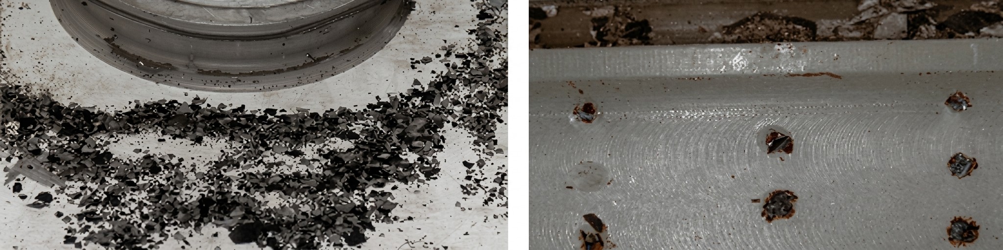
Clogged quench holes caused by metallic scale flakes, leading to irregular cooling profiles.
Inductor Maintenance and Flux Concentrators
Induction coils (inductors) are the "weakest link" in the system and require the most frequent attention. High-powered inductors can develop copper cracks due to stress corrosion or stress fatigue, especially if quench holes are drilled through the heating face. These microcracks obstruct AC flow and decrease efficiency, as the current must travel a longer path around the crack. This is particularly noticeable at higher frequencies due to the skin effect. If cracks become large enough, they will eventually leak water, rendering the coil unusable.
Cleaning is paramount for inductor longevity. Inductors should be cleaned with mild soap and plastic-bristle brushes; wire brushes should never be used as they can leave metal bristles that create stress risers. Furthermore, the buildup of scale and quench residue can act as a thermal insulator, preventing the internal water cooling from effectively removing heat from the copper surface. If the coil uses silver plating, this coating must be inspected for wear, as it helps maintain low resistivity at connection points and prevents copper oxidation.
If flux concentrators are used, they must be inspected for degradation caused by overheating or chemical attack. Overheating can stem from Joule losses within the concentrator itself or heat transfer from the workpiece. Concentrators are not perfect dielectrics; they have appreciable electrical resistivity and generate internal heat under high fields. Over time, electromagnetic forces can loosen concentrators, causing them to shift and negatively impact the heat pattern. Regular visual checks for discoloration or repositioning are mandatory. Discoloration usually indicates that the epoxy binder in a composite concentrator has begun to disintegrate due to excessive surface temperatures.
Heat-Treating Machinery and Alignment
Studies show that 70% of machines lose their usefulness due to surface degradation, specifically corrosion (20%) and mechanical wear (50%). A good visual inspection of the machinery includes looking for leaks, lubricant contamination, and corrosion on sliding components. Misalignment of the workpiece during the heating cycle is a major concern; even a minor wobble can cause localized overheating or inappropriate quench severity. Worn bearings, centers, and spindles must be replaced to maintain positioning accuracy.
Positioning accuracy is not just about part quality; it also prevents catastrophic damage to the heating coil. If a part wobbles and touches the inductor, it can cause a high-current arc that destroys both the part and the coil. Mechanical stops or "dogs" used to drive part rotation should be regularly inspected. If a part fails to rotate while the heating cycle continues, the resulting non-uniform heat pattern will likely result in a scrapped part and potential thermal distortion. Audible observation is also key—hydraulic pumps experiencing cavitation will sound like they are "pumping marbles," indicating an imminent seal failure or pump destruction.
2. Preventive Maintenance Checklist: A Structured Cadence
A world-class maintenance program relies on a structured cadence of inspections. Below is a checklist categorized by frequency to guide your maintenance team.
Daily Inspection (Shift Startup)
- Check for water and quench leaks on the floor and buswork.
- Monitor quench concentration with a refractometer.
- Verify quench and water levels in tanks.
- Visually inspect inductor for arcing marks or loose flux concentrators.
- Observe warning lights and gauges for abnormal pressure/flow readings.
- Listen for "ticking" sounds or unusual mechanical noise during operation.
Weekly Maintenance
- Clean the induction coil with mild soap and a plastic brush.
- Inspect and clean quench filters and bags; replace if necessary.
- Check conductivity of the cooling water system.
- Verify alignment of the workpiece within the inductor.
- Wipe down bus insulators and capacitor bushings.
Monthly / Quarterly Maintenance
- Perform a full thermal scan (IR camera) of the power supply and heat station.
- Check torque on all power bus fasteners using a calibrated torque wrench.
- Inspect all cooling hoses for stiffness, kinks, or signs of electrolysis.
- Test safety circuits, including the inductor ground circuit, using a jumper wire.
- Back up process recipes and machine parameters.
- Examine sacrificial anodes and replace if degraded.
Engineering Summary of System Health
To maintain high uptime and repeatability, engineers should implement a structured routine inspection based on the following priorities:
| Key Inspection Points | Critical Failure Modes | |
|---|---|---|
| Power Supply | Insulator cleanliness, door gaskets, DC bus hose length | Electrolysis, capacitor failure, dirt-induced arcing |
| Fluid Systems | Conductivity, pH, filter cleanliness, flow rates | Clogged spray holes, hose rupture, pump cavitation |
| Inductor | Contact surface flatness, copper cracks, scale buildup | Water leaks, arcing, loss of heating efficiency |
| Machinery | Alignment, lubrication, part rotation, safety circuits | Mechanical wear, inductor ground faults, part wobble |
FAQ about Induction Heat Treating Equipment Maintenance
Q: How often should I inspect my induction heating coil?
Daily visual checks are essential—look for arcing marks, loose flux concentrators, and water leaks before each shift. Weekly, clean the coil with mild soap and a plastic brush (never wire brushes). Monthly, verify alignment and check for copper cracks that can reduce efficiency and eventually cause water leaks.
Q: What water conductivity level should I maintain in my cooling system?
Keep cooling water at 10 μSiemens/cm and replace it when it reaches 100 μSiemens/cm (or 400 μSiemens/cm for systems without a DC link). High conductivity causes electrolysis, which can corrode copper tubes and create pinhole leaks. Never use standard tap water—it contains minerals that form scale inside cooling passages.
Q: Why does my power supply keep failing, and how can I prevent it?
Most power supply failures stem from dust, moisture, and loose connections. Clean all insulators to "like-new" condition to prevent carbon tracking and arcing. Use thermal imaging monthly to detect hot spots from loose bolts or poor connections. Check that cooling hoses on DC bus systems aren't too short—this prevents electrolysis that eats away copper tubes.
Conclusion: Induction Heat Treating Equipment Maintenance
Ultimately, seventy percent of machines lose their usefulness due to surface degradation (corrosion and mechanical wear). A disciplined visual and audible observation program, supported by accurate baseline data and infrared imaging, allows engineers to identify and correct these issues before they escalate into production-stopping failures. Handling inductors with the same care as high-value assets and maintaining a robust stock of spares are the final steps in a world-class maintenance strategy. By treating an inductor as a "thousand dollar bill" rather than a piece of scrap copper, facilities can ensure their induction systems remain healthy, reliable, and profitable for years to come.
Keep Learning
Simultaneous Dual-Frequency Induction Heating: When One Frequency Forces the Wrong Compromise
Key Takeaways One frequency, one compromise: When geometry demands both deep bulk heating and controlled surface gradients simultaneously, a single frequency forces an unacceptable trade-off—dual-frequency widens the process window. Give each channel a role: Assign the lower frequency to bulk penetration and the higher frequency to surface shaping. Structured recipe development follows naturally from this separation. Validate with metrics, not opinions: Dual-frequency is justified only when controlled......
Power Supplies by Application Family: Joining, Mass Heating, and Strip Processing
Key Takeaways Joining operations (brazing, soldering, bonding) demand higher frequencies and matching flexibility to handle variable coil coupling and precision surface heating. Mass heating lines (billets, bars, slabs) prioritize continuous duty, efficiency, and ruggedness at high power levels with multi-coil zone control. Strip processing requires architectures that separate control electronics from high-frequency inverter modules to cope with harsh installation environments. Specifying only kW and ......
Simultaneous Dual-Frequency Induction Power: When One Frequency Forces the Wrong Compromise
Key Takeaways Dual-frequency is justified by robustness, not complexity: It should only be adopted when a single frequency forces an unacceptable compromise between surface and bulk heating requirements. Give each frequency a defined role: Assign the lower frequency to bulk heating/penetration and the higher frequency to surface shaping—then develop recipes one variable at a time. The combining network is the engineering center of gravity: Frequency-selective coupling paths, thermal rating for worst-c......
Applying Induction Power Supplies in the Real World: Constraints That Decide Uptime and Quality
Key Takeaways Application constraints dominate real-world performance: Two induction systems with identical kW ratings can behave very differently depending on cable length, cooling water temperature, dust levels, and fixture repeatability. Design for drift, not for perfect day one: Coils deform, filters clog, sensors drift, and connectors loosen under thermal cycling. Baseline monitoring during commissioning is essential. Mechanical repeatability often beats control complexity: Improving fixturing an......
Medium- and High-Frequency Transformers in Induction Systems: Design Drivers Engineers Should Actually Care About
Key Takeaways Not Passive: Transformers set the electrical operating point for the entire induction station—coil voltage, current, capacitor stress, and inverter margin all depend on transformer choice. Frequency Effects: At higher frequencies, winding losses and stray capacitance dominate; a transformer that looks fine on turns ratio can fail a duty-cycle test if loss distribution is wrong. Placement Matters: Moving the transformer and capacitor bank closer to the coil reduces high-frequency loop len......
Load Matching in Induction Heating: Designing for Stability, Efficiency, and Real-World Variation
Key Takeaways Dynamic Load: Induction heating loads are not fixed—coupling, material properties, and temperature all shift impedance during operation, making matching a continuous design challenge. Q Factor Matters: High-Q loads can produce large circulating currents and capacitor stress even at modest delivered kW; design for the worst-case kVA, not just power. Discrete Ranges Win: Transformer taps and capacitor steps that cover discrete matching ranges outperform a single broad-range configuration f......