
Beyond the Coil: Accessory Equipment and Work Handling in Induction Heat Treating
13 min
- 1. Automated Handling: Robots, Gantries, and Pick-and-Place Units
- 2. Batch Presentation: Hoppers and Magazines
- 3. Conveyors and Rotary Tables: The Arteries of the Process
- 4. Specialized Handling for Specific Geometries
- 5. The Quench and Tooling Interface
- 6. Summary of Handling Considerations
- FAQ about Induction Heat Treating Accessory Equipment
Key Takeaways
Automation is Critical: Robots, gantries, and pick-and-place units enable high-speed, repeatable induction heat treating by precisely controlling part positioning and timing.
Handling Must Match Geometry: Different part geometries—from long bar stock to thin-wall tubing—require specialized feeding, rotation, and conveyance systems to ensure uniform heating and prevent damage.
Ground Loops and EM Forces Are Hidden Risks: Induced currents can destroy precision bearings through pitting, while electromagnetic forces can cause unstable part movement; both must be mitigated through proper isolation and constraint.
Tooling Material Matters: Work-holding centers made of magnetic steel overheat and distort hardness patterns; stainless steel and electrical isolation are essential for consistent quality and equipment longevity.
In the world of induction heat treating, the design of the induction coil often takes center stage. Engineers spend countless hours optimizing frequency, power density, and coupling distances to achieve the perfect metallurgical transformation. However, for a process to be truly production-ready, repeatable, and safe, the focus must shift "beyond the coil" to the accessory equipment and work handling systems. These systems are the physical backbone of the process, responsible for integrating coil design, quenching, and part-holding fixtures into a cohesive, automated workflow.
Induction heating's unique ability to heat parts rapidly—often in seconds—makes it an ideal candidate for high-speed automation. In automatic systems, work handling is what transfers the workpiece through every critical stage: loading, preheating, induction heating, quenching, and post-heating operations like tempering and unloading. Without robust accessory equipment, even the most perfectly designed coil cannot deliver consistent quality or meet modern production throughput requirements. The success of the heat treat cell depends on the seamless coordination between the electrical power source and the mechanical handling hardware.
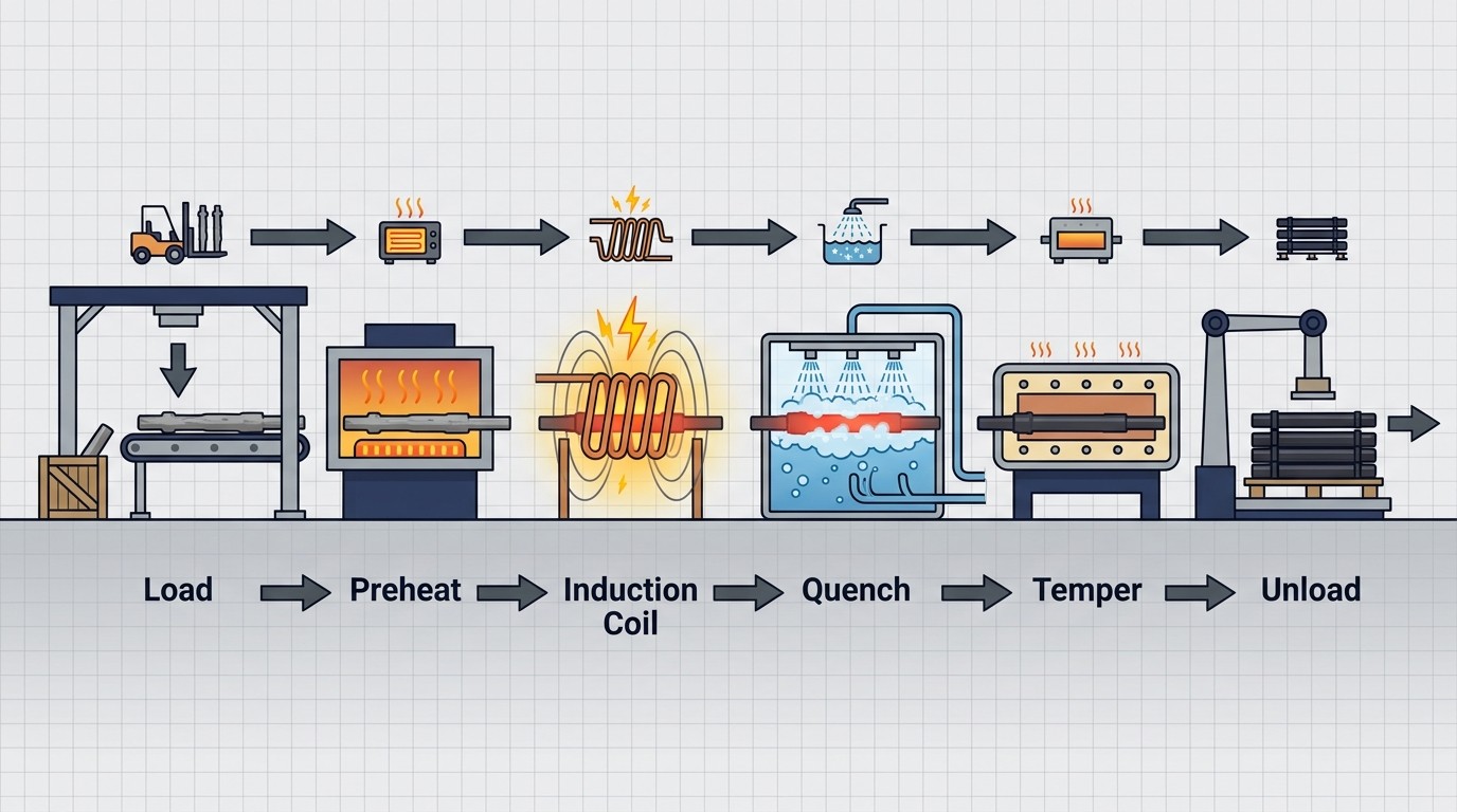
A systems-level view of the induction heat treating workflow, illustrating the integration of loading, heating, quenching, and unloading stages.
1. Automated Handling: Robots, Gantries, and Pick-and-Place Units
Modern high-production environments increasingly rely on robots and gantries to manage part movement. This is particularly true for heavy or irregularly shaped components where manual loading is either cost-inefficient or physically unrealistic. Robots and gantries provide the flexibility to handle virtually any size or shape of component and can often be integrated into existing induction setups. Their implementation, however, introduces a layer of complexity regarding control and safety that engineers must address during the design phase.
Robots and gantries come equipped with their own electronic controls, necessitating a sophisticated "handshaking" interface between the induction machine's primary control and the robotic controller. This interface clearly defines which system has "ownership" of the part at any given time. For instance, the robot must signal when it has safely placed a part in the heating position and retracted its end-effector before the induction power can be energized. Conversely, the induction system must signal when the quench cycle is complete so the robot can safely retrieve the part. Without this rigorous handshaking, there is a high risk of collisions that can damage the induction coil, the part-holding tooling, or the robot arm itself.
Safety Note
Safety is the primary concern when moving machinery operates in proximity to plant personnel. For lightweight workpieces, engineers often design systems with the flexibility to operate with or without the automated handling system. This modular approach allows production to continue manually if the robot or gantry is out of service for maintenance. In these hybrid setups, positive shot pins are a critical safety feature. These pins provide a mechanical interlock that ensures the robot cannot move while an operator is performing manual loading or unloading within the robot's operational envelope, preventing accidental activation and protecting the workforce from the high forces generated by industrial automation.
For simpler automation tasks, pick-and-place units offer a cost-effective alternative. These units typically provide linear or rotary motion similar to a robot but without the sophisticated control electronics or the wide-ranging, free range of motion. In many installations, only the pick-and-place mechanics are purchased, and the control logic is integrated directly into the machine's primary Programmable Logic Controller (PLC). This simplifies the overall system architecture by eliminating the need for a separate robot controller and a complex handshaking protocol, provided the part geometry is consistent and the path is straightforward.
2. Batch Presentation: Hoppers and Magazines
When processing families of similar parts, hoppers and magazines are the standard accessories for part presentation. The choice between them depends on the initial state of the parts. Magazines typically hold a defined quantity of parts in a structured cartridge or stack. These parts are then dropped either directly into the induction coil's workspace or onto a transfer system, such as a conveyor, for delivery to the heating station. Magazines are ideal for parts that are already oriented and require precise, sequential feeding.
Hoppers, by contrast, are designed to handle bulk tubs of randomly oriented parts. To be useful for induction heating, these parts must be sorted and oriented before they enter the system. Sorting can be achieved through various mechanical and magnetic means, including vibration, magnetic orientation, or specially designed mechanical "fingers" that catch and align the parts. For example, in the hardening of bolts and screws, the hopper system sorts the fasteners and indexes them into the coil. This ensures that every part is presented in the exact same orientation, allowing for the precise, repeatable heating and quenching necessary for high-strength hardware.
3. Conveyors and Rotary Tables: The Arteries of the Process
Conveyors are ubiquitous in induction systems, functioning as the arteries that move parts through the heat treat cell. They can be belt, chain, or cam-driven and operate in either continuous or indexed modes. Indexed conveyors, often driven by servomotors or mechanical cam switches, are essential when a part must remain stationary inside the coil for a specific duration. Choosing the right conveyor requires a deep understanding of the operating environment, which is often characterized by extreme heat and constant exposure to corrosive quenchants.
Material selection for conveyors is paramount. Stainless steel mesh or chain is commonly used to prevent corrosion from water-based or polymer quenchants. Furthermore, engineers must be cautious when using plain carbon steel components. If a carbon steel belt or conveyor structure is positioned too close to the induction coil, it may be heated inductively along with the workpiece. This not only wastes energy and reduces process efficiency but can also cause the conveyor itself to overheat, leading to mechanical failure or belt stretch. In high-production environments, preventing the conveyor from becoming a secondary "load" for the inductor is a critical design goal.
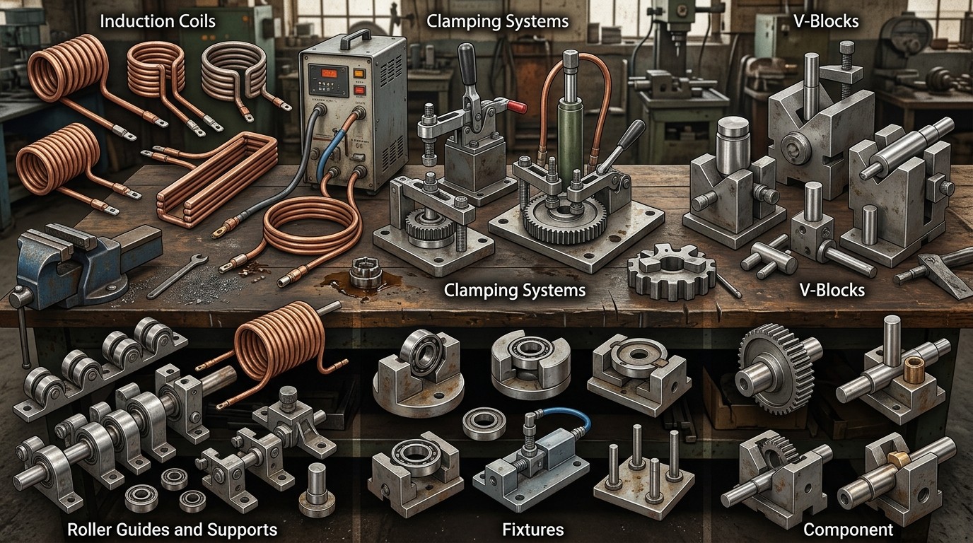
A variety of specialized accessory equipment, including V-blocks, roller guides, and clamping systems used to ensure precise part orientation during induction heating.
Electromagnetic Forces Warning
Another often-overlooked factor is the impact of electromagnetic (EM) forces. As lightweight workpieces pass through the high-intensity magnetic fields of an induction coil, these forces can cause unintended part movement or vibration. If the handling system does not provide sufficient constraint, the parts may shift out of alignment, leading to non-uniform heating. For some applications, the conveyor must be designed to carry hot parts away immediately after heating, requiring materials that can withstand extreme temperatures without degrading. In the event of a downstream stoppage, the system must also be capable of backing hot parts out of the induction zone to prevent damage to the equipment or the parts themselves.
Rotary tables, or carousels, are a popular choice for cellular manufacturing and high-volume production. These tables feature nests for a specific number of parts and rotate to bring each part into the induction zone sequentially. The primary benefit of a rotary table is its efficiency in floor space usage; unheated parts are loaded and heat-treated parts are unloaded in virtually the same location. This allows for very high throughput, as a large number of parts can be passed through a coil in rapid succession. Rotary tables are frequently combined with other handling equipment—such as robots or pick-and-place units—to create fully automated cells for components like ball studs or automotive gear blanks.
4. Specialized Handling for Specific Geometries
Different part geometries present unique handling challenges that require specialized accessory equipment to ensure metallurgical success and equipment longevity:
Long Bar Stock
Delivering long, thin bar stock requires mechanisms like unscramblers to separate bars from a bundle and line them up for continuous feeding. A feeding mechanism, often consisting of upper and lower pinch rollers, must maintain a constant linear velocity through the coil to ensure uniform heating. Any mislocation or variation in speed can lead to localized overheating or underheating. A critical risk in these systems is the formation of "ground loops"—continuous electrical paths from end-to-end through the handling system. If these loops are not broken, induced currents can flow through the equipment's rollers and bearings, causing catastrophic damage. To prevent this, isolation techniques must be employed.
Pipes and Tubes
Handling equipment for pipes and tubes must grip and rotate the part without causing distortion or mechanical damage to the relatively thin walls. A major failure mode during hardening is the "banana effect." This occurs when quenchant becomes trapped inside the tube as the end passes through the quench ring. The trapped liquid causes a lower temperature on the bottom of the tube, leading to non-uniform cooling and severe warping (the banana-like curvature). In high-precision applications, the handling system must facilitate drainage or be followed by a straightening operation to maintain tight dimensional limits.
Thin-Wall Tubing and Wires
For long products like ACR copper tubing, high-speed "basket-to-basket" systems are used. These systems can process tubing with wall thicknesses as low as 0.32 mm at speeds up to 10 m/s (600 m/min). The engineering challenge here is to manage these extreme speeds while preventing mechanical damage. Precise, synchronized rotation of both the supply and take-up baskets is the key factor in maintaining product integrity and preventing line breaks that would lead to significant downtime.
Metal Strips and Large Plates
Strip products, used for coatings or edge hardening, require precise lateral positioning inside the heating coil. Electromagnetic forces are particularly problematic for strips, as they can cause the thin metal to move or flutter within the coil, especially in transverse flux heaters. For large steel plates, such as grader blades, the handling system must move massive rectangular sections through the induction zone at constant speeds. These systems often operate in the megawatt power range, and the handling rollers must withstand both high operating temperatures and significant mechanical forces to prevent plate distortion.
5. The Quench and Tooling Interface
The accessory equipment isn't just about moving parts; it is critical for maintaining the integrity of the heat treat pattern. Work holding components—including centers, cups, nests, and pedestals that support the part ends—drastically influence the final metallurgical results. For instance, if centers or cups are made of magnetic steel, they can be inductively heated. This overheating of the tooling can cause variations in the hardness pattern runout at the ends of a shaft. To minimize this risk, these components should be made of stainless steel, which allows the induction field to heat the end of the workpiece without overheating or degrading the supporting centers.
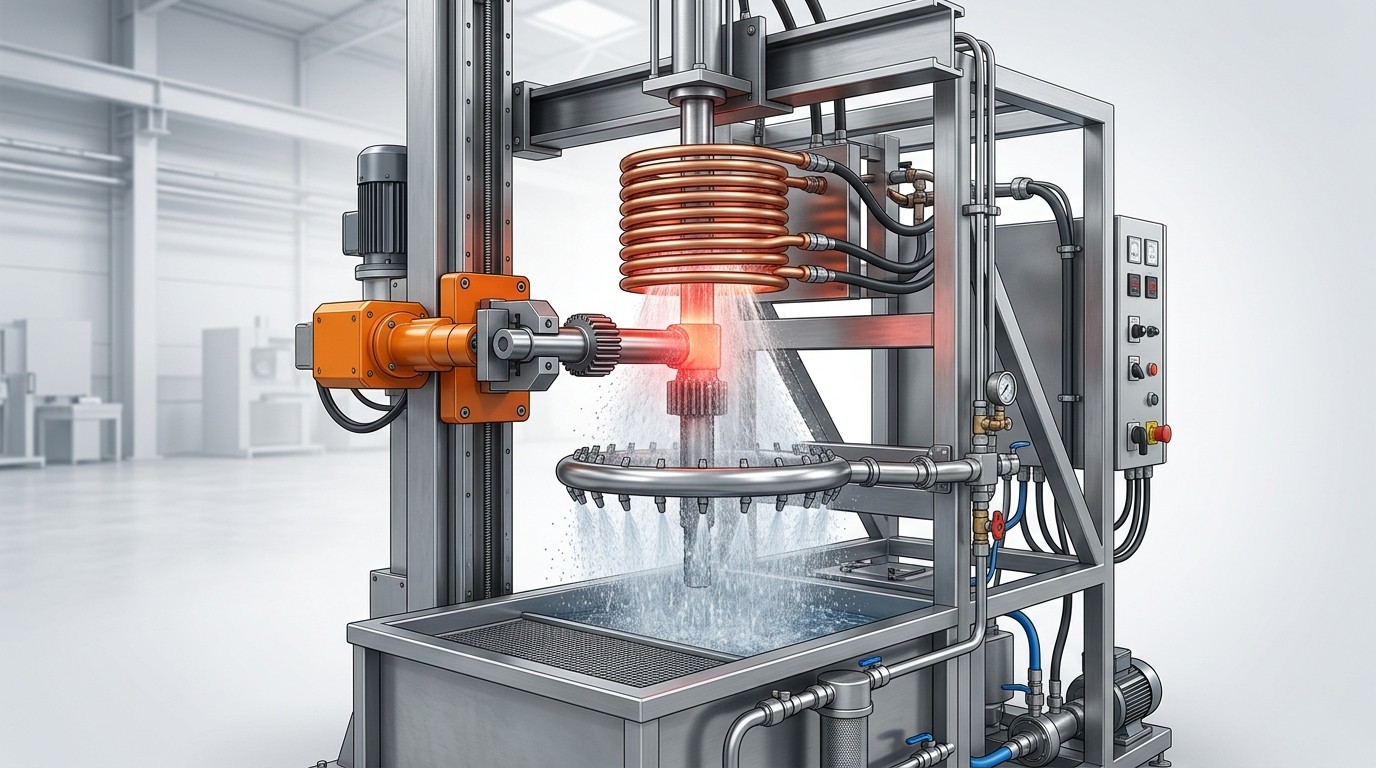
An integrated induction heating and quenching station, where the handling system must precisely align the part between the induction coil and the quench ring.
Electrical Isolation of Tooling
Electrical isolation of the tooling is another vital consideration. To prevent ground loops from forming through the part, the tooling, and the machine bearings, at least one of the work-holding centers is usually electrically isolated. Even though the induced currents might be relatively small, they are sufficient to cause "pitting" and irreparable damage to high-precision bearings. This damage leads to increased vibration, loss of part concentricity, and eventually, costly machine downtime. Ensuring that the electrical path is broken through proper insulation is as important as the mechanical design of the center itself.
6. Summary of Handling Considerations
| Handling System Type | Key Engineering Consideration | Primary Benefit |
|---|---|---|
| Robots/Gantries | Control Handshaking & Safety Envelopes | Flexibility for heavy/complex parts |
| Conveyors | Heat/Corrosion Resistance & EM Forces | Continuous high-volume throughput |
| Rotary Tables | Nesting Precision & Cellular Layout | Efficient floor space; high production |
| Bar/Tube Feeders | Ground Loop Prevention & Trapped Quenchant | Consistent linear velocity & straightness |
| Basket-to-Basket | Sync Rotation & High-Speed Handling | Annealing wires and thin-wall tubing |
FAQ about Induction Heat Treating Accessory Equipment
Q: Why is automated handling equipment necessary for induction heating systems?
Induction heating operates at extremely high speeds—often heating parts in just seconds—making manual handling impractical for high-volume production. Automated systems like robots, gantries, and conveyors ensure consistent part positioning, enable rapid throughput, and maintain the precise timing required for repeatable metallurgical results. They also improve safety by removing operators from hazardous zones with high temperatures and electromagnetic fields.
Q: What are ground loops and why are they dangerous in induction heating systems?
Ground loops are unintended electrical paths that form through handling equipment like rollers, bearings, and support structures. When parts move through the induction coil, currents can be induced in these continuous metal paths, causing severe damage to precision bearings through pitting and overheating. Engineers prevent this by incorporating electrical isolation—typically using non-conductive materials or insulated work-holding centers—to break the electrical circuit.
Q: How does part geometry affect the choice of handling equipment?
Different geometries require specialized solutions: long bar stock needs pinch rollers for constant velocity feeding; pipes and tubes require rotation systems that prevent quenchant trapping and warping; thin-wall tubing demands high-speed basket-to-basket systems; and large plates need heavy-duty rollers to prevent distortion. The handling system must account for electromagnetic forces, heat exposure, and the specific quenching requirements of each part shape to achieve uniform heating and consistent quality.
Conclusion: Induction Heat Treating Accessory Equipment
In conclusion, the success of an induction heat treating process depends as much on the accessory equipment surrounding the coil as the coil itself. By carefully selecting and integrating robots, conveyors, hoppers, and specialized work-holding fixtures, and by proactively addressing risks like ground loops and EM interference, engineers can ensure a process that is not only fast but repeatable, robust, and safe for the long term. Designing for the whole system, rather than just the inductor, is the hallmark of a world-class heat treating operation.
Keep Learning
Simultaneous Dual-Frequency Induction Heating: When One Frequency Forces the Wrong Compromise
Key Takeaways One frequency, one compromise: When geometry demands both deep bulk heating and controlled surface gradients simultaneously, a single frequency forces an unacceptable trade-off—dual-frequency widens the process window. Give each channel a role: Assign the lower frequency to bulk penetration and the higher frequency to surface shaping. Structured recipe development follows naturally from this separation. Validate with metrics, not opinions: Dual-frequency is justified only when controlled......
Power Supplies by Application Family: Joining, Mass Heating, and Strip Processing
Key Takeaways Joining operations (brazing, soldering, bonding) demand higher frequencies and matching flexibility to handle variable coil coupling and precision surface heating. Mass heating lines (billets, bars, slabs) prioritize continuous duty, efficiency, and ruggedness at high power levels with multi-coil zone control. Strip processing requires architectures that separate control electronics from high-frequency inverter modules to cope with harsh installation environments. Specifying only kW and ......
Simultaneous Dual-Frequency Induction Power: When One Frequency Forces the Wrong Compromise
Key Takeaways Dual-frequency is justified by robustness, not complexity: It should only be adopted when a single frequency forces an unacceptable compromise between surface and bulk heating requirements. Give each frequency a defined role: Assign the lower frequency to bulk heating/penetration and the higher frequency to surface shaping—then develop recipes one variable at a time. The combining network is the engineering center of gravity: Frequency-selective coupling paths, thermal rating for worst-c......
Applying Induction Power Supplies in the Real World: Constraints That Decide Uptime and Quality
Key Takeaways Application constraints dominate real-world performance: Two induction systems with identical kW ratings can behave very differently depending on cable length, cooling water temperature, dust levels, and fixture repeatability. Design for drift, not for perfect day one: Coils deform, filters clog, sensors drift, and connectors loosen under thermal cycling. Baseline monitoring during commissioning is essential. Mechanical repeatability often beats control complexity: Improving fixturing an......
Medium- and High-Frequency Transformers in Induction Systems: Design Drivers Engineers Should Actually Care About
Key Takeaways Not Passive: Transformers set the electrical operating point for the entire induction station—coil voltage, current, capacitor stress, and inverter margin all depend on transformer choice. Frequency Effects: At higher frequencies, winding losses and stray capacitance dominate; a transformer that looks fine on turns ratio can fail a duty-cycle test if loss distribution is wrong. Placement Matters: Moving the transformer and capacitor bank closer to the coil reduces high-frequency loop len......
Load Matching in Induction Heating: Designing for Stability, Efficiency, and Real-World Variation
Key Takeaways Dynamic Load: Induction heating loads are not fixed—coupling, material properties, and temperature all shift impedance during operation, making matching a continuous design challenge. Q Factor Matters: High-Q loads can produce large circulating currents and capacitor stress even at modest delivered kW; design for the worst-case kVA, not just power. Discrete Ranges Win: Transformer taps and capacitor steps that cover discrete matching ranges outperform a single broad-range configuration f......