
Metallurgy Essentials for Induction Heat Treating: Microstructures, Critical Temperatures, and What They Change
12 min
- The Atomic Foundations of Steel
- Crystalline Order and Space Lattices
- Critical Temperatures and Phase Transformations
- Latent Heat and Thermal Arrest
- The Iron–Iron Carbide (Fe–Fe3C) Diagram
- Equilibrium vs. Non-Equilibrium: The Reality of IHT
- Microstructures: From Pearlite to Martensite
- Practical Implications for the Induction Engineer
- The Role of Alloying Elements
- FAQ about Induction Heat Treating Metallurgy
Key Takeaways
Crystal Structure Dictates Properties: Iron transforms between Body-Centered Cubic (BCC) ferrite and Face-Centered Cubic (FCC) austenite at critical temperatures. This allotropic transformation is the foundation of steel hardening.
Dynamic Critical Temperatures: Under rapid induction heating (100–1500°C/s), the Ac1 and Ac3 critical temperatures shift upward significantly. Relying on the equilibrium Fe–Fe3C diagram alone leads to incomplete austenitization.
Martensite = Trapped Carbon: Martensite's hardness comes from carbon atoms trapped in a distorted Body-Centered Tetragonal (BCT) lattice during rapid quenching—not from chemical changes.
Prior Microstructure is Critical: Quenched and Tempered (Q&T) starting structures with fine carbides respond best to induction hardening. Annealed or spheroidized structures require higher temperatures and longer times.
Alloying Elements Improve Hardenability: Elements like Mn, Ni, and Cr shift TTT/CCT curves to the right, allowing martensitic hardening with less severe quenching and reduced cracking risk.
Metallurgy as an art has been practiced since the beginning of human history, but as a rigorous science, it traces its origin to the early 1860s when light optical microscopy began to be used to inspect the structure of metals and alloys. For the modern induction heat treating engineer, metallurgy is not just a theoretical field; it is a practical domain that deals with extracting, refining, and alloying metals to develop desirable structures and obtain the industrial properties needed for high-performance components. Physical metallurgy, a subset of this field, focuses specifically on the physical, chemical, and mechanical characteristics of metals and their mixtures, known as alloys.
The primary goal of thermal treatment, or heat treatment, is to manipulate these characteristics by controlling the temperature, heating rate, holding time, and cooling intensity. By doing so, engineers can arrive at a specific microstructure that dictates industrial properties such as hardness, strength, ductility, toughness, and wear resistance. In the world of induction heat treating (IHT), understanding these fundamental principles is the difference between a successful hardening operation and a failed component prone to cracking or distortion.
The Atomic Foundations of Steel
Before diving into the complexities of steel behavior during induction heating, it is essential to ground our understanding in basic material definitions. At the most fundamental level, an element is a pure substance that cannot be separated chemically into any other type of substance. Elements are composed of atoms, which consist of a solid nucleus of neutrons and protons surrounded by circulating electrons. In a neutral atom, the negative electrical charge of the electrons is balanced by the positive charge of the protons in the nucleus. When two or more elements combine, they form a molecule, and chemically bonded elements produce compounds with properties often vastly different from their constituent parts. For instance, water is a compound formed from two gases (hydrogen and oxygen) but exists as a liquid at room temperature.
In metallurgy, we frequently work with mixtures—combinations of elements or compounds that are not chemically joined and can be relatively easily separated. A solution is a special kind of mixture where one substance (the solute) is dissolved in another (the solvent). For induction engineers, the concept of a solid solution is paramount. Alloys like bronze (copper and tin) or brass (copper and zinc) are solid solutions that typically require elevated temperatures to form. Steel itself is primarily a solid solution of carbon in iron, often containing more than 98% iron.
Crystalline Order and Space Lattices
When atoms cluster together in a solid, they form a crystal oriented in an orderly three-dimensional fashion known as a space lattice. In iron and steel, the specific crystalline structure is not static; it changes based on factors like temperature and pressure. This phenomenon of a material existing in different crystalline forms is known as allotropic transformation. This structural shifting is what allows us to "harden" steel by trapping carbon within the lattice during rapid cooling.
At the core of ferrous metallurgy are two primary lattices: the Body-Centered Cubic (BCC) and the Face-Centered Cubic (FCC) structures. In a BCC lattice, atoms are arranged at each corner of a cube with one additional atom positioned at the very center. This structure is relatively brittle and is the standard form for pure iron at room temperature. In contrast, the FCC lattice features an atom at each corner and six additional atoms—one at the center of each of the six faces of the cube—with no atom in the center. The FCC structure is more "closely packed," meaning it occupies less volume and has a greater density than the BCC structure, despite iron being noticeably more ductile in this state.
Critical Temperatures and Phase Transformations
The behavior of iron and steel is governed by "critical temperatures" that signify a resistance to structural transformation. These transformations are diffusion-driven processes. To distinguish between cycles, we use specific notation: the symbol "A" stands for arret (French for arrest), while subscripts designate the cycle. We use "c" for heating (from the French chauffage) and "r" for cooling (refroidissement). For example, Ac3 refers to the upper critical temperature during heating where austenitization completes, while Ar3 refers to the corresponding transformation during cooling.
Pure iron exists in several distinct allotropic forms depending on the temperature range:
- Alpha-Iron (Ferrite): Existing below approximately 912°C (1674°F), this has a BCC structure. It is the form stable at room temperature and exhibits strong ferromagnetic properties. Above 768°C (the Curie point or A2), it loses these magnetic properties and becomes paramagnetic.
- Gamma-Iron (Austenite): Formed between 912°C and 1392°C (2538°F), iron adopts an FCC structure. Austenite is non-magnetic, more ductile, and is the phase where carbon solubility is highest, making it the critical starting point for hardening.
- Delta-Iron: Above 1392°C, the lattice transforms back to a BCC structure until the melting point is reached at approximately 1528°C (2782°F). This phase is rarely encountered by induction practitioners unless they are involved in melting or welding.
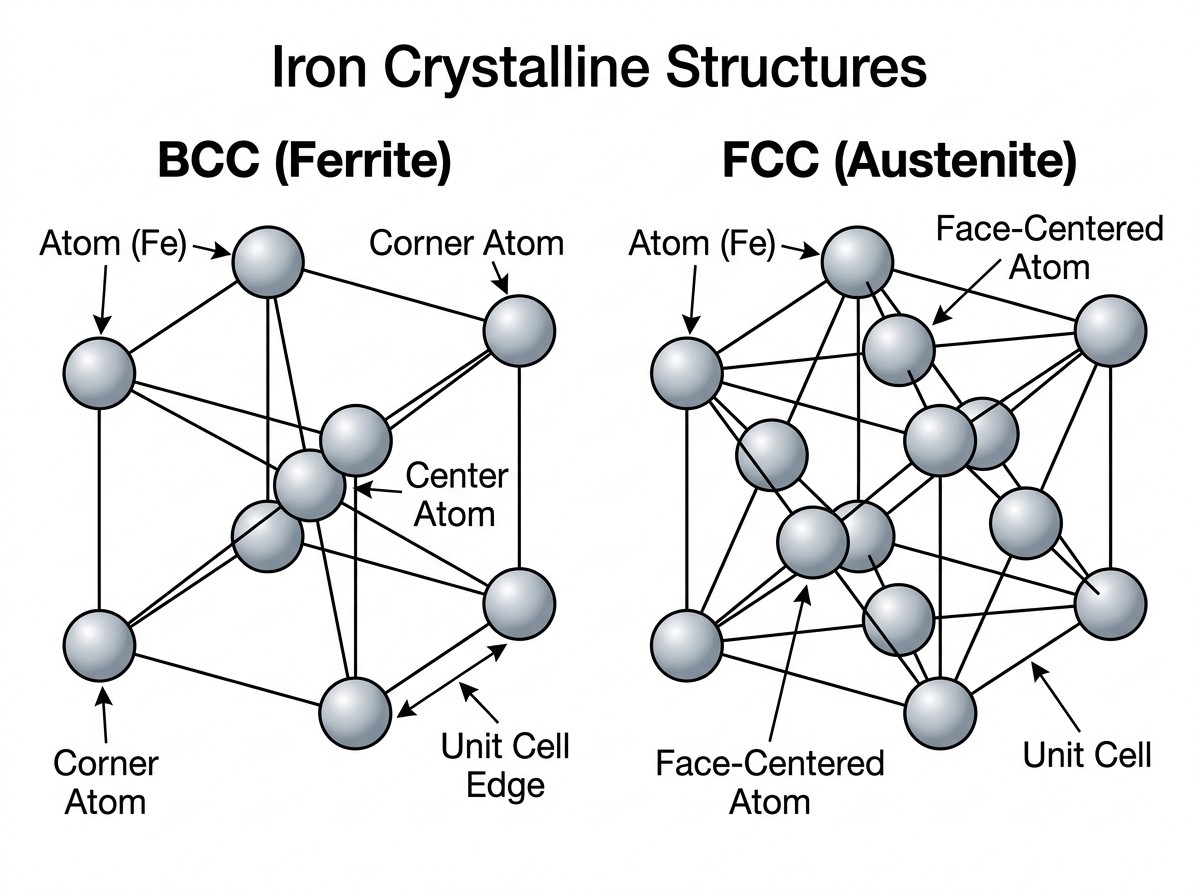
Figure 1: Comparison of the Body-Centered Cubic (BCC) ferrite and Face-Centered Cubic (FCC) austenite lattices in iron.
Latent Heat and Thermal Arrest
When iron structure changes from one type to another during allotropic transformation, there is a thermal effect called the latent heat of transformation. This is additional energy that must be accounted for in any thermal process. On heating, energy is absorbed to support the crystalline transformation; on cooling, energy is released. This release or absorption of energy creates a "temperature plateau" or arrest point on a heating/cooling curve, where the temperature rise or fall is appreciably slowed down or stopped while the material reorganizes its atomic structure.
Design Note: Latent Heat of Alpha-to-Gamma Transformation
For pure iron, the latent heat for the alpha-to-gamma transformation at 912°C is approximately 16 kJ/kg. During steady heating with low heat intensity, you would see the temperature rise pause at this point. In induction heating, where power densities are extremely high, this plateau may be less visible but still consumes a portion of the applied energy. Understanding these arrest points is vital for precision temperature control, as the material "resists" changing temperature until the structural transformation is complete.
The Iron–Iron Carbide (Fe–Fe3C) Diagram
Among all industrial alloys, steel is the most common, ideally treated as a binary alloy of iron and carbon. Most steels used in induction hardening contain between 0.2% and 1% carbon. The Iron-Iron Carbide equilibrium diagram serves as a fundamental roadmap for heat treaters, plotting temperature against carbon content to show which phases are present under equilibrium (very slow) conditions. It helps estimate the ranges for various heat treatments, from annealing to hardening.
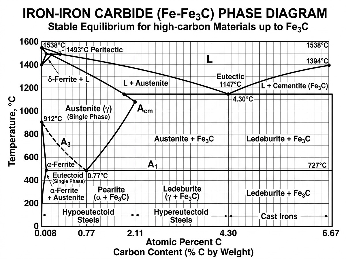
Figure 2: The Iron–Iron Carbide (Fe–Fe3C) equilibrium phase diagram showing critical temperature lines and phase regions for steels.
Key transition points on this diagram include:
- A1 (Lower Critical Temp): At approximately 727°C (1341°F), austenite begins to form from the prior pearlite/ferrite structure during heating.
- A3 (Upper Critical Temp): The temperature at which the transformation to austenite is complete for hypoeutectoid steels (those with less than 0.77% carbon). This line decreases as carbon content increases.
- Eutectoid Point: At approximately 0.77% carbon (Point S), austenite transforms directly into a 100% lamellar mixture of ferrite and cementite called pearlite.
Equilibrium vs. Non-Equilibrium: The Reality of IHT
It is vital to remember that the Fe–Fe3C diagram is valid only for equilibrium conditions—very slow heating and cooling at 1 atm. Real-world induction hardening is far from equilibrium. Under equilibrium, transformations are reversible; however, commercial applications involve rapid heating rates (often 100°C/s to 1500°C/s) and intense spray quenching. This discrepancy leads to thermal hysteresis, where critical temperatures shift based on the rate of change.
Warning: Dynamic Critical Temperatures
During rapid induction heating, the Ac1 and Ac3 temperatures shift upward. Conversely, during intense cooling, the Ar1 and Ar3 temperatures lower significantly. This means a recipe based strictly on the equilibrium diagram will likely result in incomplete austenitization because the "real" transformation temperature has been pushed higher by the speed of the process. For an induction engineer, accounting for this "dynamic" critical temperature is essential for ensuring that the entire required case depth has fully transformed to austenite before the quench begins.
Microstructures: From Pearlite to Martensite
The end goal of most induction hardening operations is the creation of martensite—a hard, strong, nonequilibrium phase. When austenite is rapidly cooled, there is no time for carbon to diffuse out of the lattice. Instead, the carbon is trapped, distorting the crystalline structure from FCC to Body-Centered Tetragonal (BCT). This lattice distortion, along with high densities of crystal imperfections (dislocations), is the source of the high hardness characteristic of as-quenched steel. The chemical composition of martensite is identical to the parent austenite because the transformation is diffusionless.
Depending on the cooling rate and carbon content, several other structures can form:
- Pearlite: A lamellar mixture of ferrite and cementite. At high temperatures, the eutectoid reaction is sluggish, producing coarse pearlite. Fine pearlite forms at more moderate cooling rates (620°C to 550°C) and offers better wear resistance and strength.
- Bainite: Formed at cooling rates between pearlite and martensite. Lower bainite (380°C to 220°C) has an acicular morphology similar to martensite and is both harder and tougher than upper bainite, where carbides segregate between ferrite plates.
- Retained Austenite (RA): If the quenching does not reach the Mf (martensite finish) temperature, some austenite remains untransformed. RA is generally undesirable in induction hardening as it can reduce hardness and dimensional stability.
Practical Implications for the Induction Engineer
For the engineer on the shop floor, interpreting these metallurgical basics leads to concrete procedural decisions. The prior microstructure of the "green" part dictates how it will respond to rapid heating. A Quenched and Tempered (Q&T) initial structure is the most favorable because it consists of fine carbides that dissolve quickly into austenite, allowing for lower hardening temperatures and consistent case depths.
Conversely, annealed or spheroidized structures with coarse carbides respond poorly to short-time induction cycles. They require higher temperatures and longer soak times to achieve complete austenitization, which increases the risk of grain coarsening and oxidation. Furthermore, engineers must be wary of decarburization—the loss of surface carbon during prior hot working. Since carbon determines achievable hardness (roughly $HRC \approx 50 \times \%C + 38$ for 0.25–0.5%C steels), a decarburized surface layer will remain soft even after successful induction hardening, potentially leading to premature fatigue failure.
The Role of Alloying Elements
While carbon is the primary driver of hardness, alloying elements like Manganese, Nickel, and Chromium modify the transformation kinetics. Most alloys improve hardenability, shifting the "nose" of the TTT/CCT curves to the right. This allows engineers to achieve full martensitic hardening with less severe quenchants (like oil or polymer) or at lower cooling velocities, reducing the probability of crack initiation and shape distortion.
Conclusion: Metallurgy Essentials for Induction Heat Treating
Metallurgy for induction heat treating is a balancing act between the nonequilibrium nature of rapid heating and the inherent resistance of the material to structural change. By understanding critical temperatures, the impact of heating rates on thermal hysteresis, and the nuances of prior microstructures, engineers can develop robust recipes that ensure high-quality, durable components.
FAQ about Induction Heat Treating Metallurgy
Q: Why can't I use the Iron-Iron Carbide diagram directly for induction hardening?
The Fe–Fe3C diagram only applies to equilibrium conditions with very slow heating and cooling. In induction hardening, you're heating at 100–1500°C/s and quenching rapidly. This shifts critical temperatures upward during heating (Ac1, Ac3) and downward during cooling (Ar1, Ar3). If you follow equilibrium temperatures, you'll likely get incomplete austenitization because the real transformation temperature has moved higher due to the process speed.
Q: What makes martensite so hard compared to other steel microstructures?
Martensite forms when austenite is cooled so rapidly that carbon atoms get trapped inside the iron lattice instead of diffusing out. This creates a distorted Body-Centered Tetragonal (BCT) structure with high internal stress and crystal defects. The lattice distortion and trapped carbon—not a chemical change—are what give martensite its characteristic high hardness.
Q: Why does prior microstructure matter for induction hardening success?
Prior microstructure determines how quickly carbides dissolve during rapid heating. Quenched and Tempered (Q&T) structures with fine carbides dissolve easily, allowing lower hardening temperatures and consistent results. Annealed or spheroidized structures with coarse carbides need higher temperatures and longer times to fully austenitize, increasing risks of grain growth, oxidation, and distortion.
Keep Learning
Simultaneous Dual-Frequency Induction Heating: When One Frequency Forces the Wrong Compromise
Key Takeaways One frequency, one compromise: When geometry demands both deep bulk heating and controlled surface gradients simultaneously, a single frequency forces an unacceptable trade-off—dual-frequency widens the process window. Give each channel a role: Assign the lower frequency to bulk penetration and the higher frequency to surface shaping. Structured recipe development follows naturally from this separation. Validate with metrics, not opinions: Dual-frequency is justified only when controlled......
Power Supplies by Application Family: Joining, Mass Heating, and Strip Processing
Key Takeaways Joining operations (brazing, soldering, bonding) demand higher frequencies and matching flexibility to handle variable coil coupling and precision surface heating. Mass heating lines (billets, bars, slabs) prioritize continuous duty, efficiency, and ruggedness at high power levels with multi-coil zone control. Strip processing requires architectures that separate control electronics from high-frequency inverter modules to cope with harsh installation environments. Specifying only kW and ......
Simultaneous Dual-Frequency Induction Power: When One Frequency Forces the Wrong Compromise
Key Takeaways Dual-frequency is justified by robustness, not complexity: It should only be adopted when a single frequency forces an unacceptable compromise between surface and bulk heating requirements. Give each frequency a defined role: Assign the lower frequency to bulk heating/penetration and the higher frequency to surface shaping—then develop recipes one variable at a time. The combining network is the engineering center of gravity: Frequency-selective coupling paths, thermal rating for worst-c......
Applying Induction Power Supplies in the Real World: Constraints That Decide Uptime and Quality
Key Takeaways Application constraints dominate real-world performance: Two induction systems with identical kW ratings can behave very differently depending on cable length, cooling water temperature, dust levels, and fixture repeatability. Design for drift, not for perfect day one: Coils deform, filters clog, sensors drift, and connectors loosen under thermal cycling. Baseline monitoring during commissioning is essential. Mechanical repeatability often beats control complexity: Improving fixturing an......
Medium- and High-Frequency Transformers in Induction Systems: Design Drivers Engineers Should Actually Care About
Key Takeaways Not Passive: Transformers set the electrical operating point for the entire induction station—coil voltage, current, capacitor stress, and inverter margin all depend on transformer choice. Frequency Effects: At higher frequencies, winding losses and stray capacitance dominate; a transformer that looks fine on turns ratio can fail a duty-cycle test if loss distribution is wrong. Placement Matters: Moving the transformer and capacitor bank closer to the coil reduces high-frequency loop len......
Load Matching in Induction Heating: Designing for Stability, Efficiency, and Real-World Variation
Key Takeaways Dynamic Load: Induction heating loads are not fixed—coupling, material properties, and temperature all shift impedance during operation, making matching a continuous design challenge. Q Factor Matters: High-Q loads can produce large circulating currents and capacitor stress even at modest delivered kW; design for the worst-case kVA, not just power. Discrete Ranges Win: Transformer taps and capacitor steps that cover discrete matching ranges outperform a single broad-range configuration f......