
The Thermal Titans: A Comprehensive Guide to Heat Exchanger Engineering
15 min
- What is a Heat Exchanger?
- Anatomy of a Titan: Construction and Materials
- Classification: Organizing the Options
- The Engineering Logic: Selection and Trade-offs
- Core Functional Requirements
- The Engineer’s Checklist
In the vast ecosystem of modern industry, there exists a silent, critical component that keeps our world running. From the massive cooling towers of power plants—towering concrete giants releasing great plumes of steam into the sky—to the precise climate control of your office building that maintains a perfect 22°C regardless of the weather outside, and even the processing of the milk in your refrigerator that began its journey at a dairy farm hundreds of kilometers away, one device is central to it all: the Heat Exchanger.
Walk through any industrial facility and you’ll see them everywhere, though you might not recognize them at first. They’re the cylindrical vessels wrapped in insulation, the stacks of plates bolted together in the corner, the finned coils suspended from ceilings. While they may seem like simple metal boxes or piping systems to the untrained eye, heat exchangers are sophisticated engineering marvels that represent humanity’s mastery over one of nature’s most fundamental forces: heat flow.
This article explores the fundamental engineering framework of these devices, breaking down how they work, how they are built, and the rigorous science behind selecting the right one for the job. Whether you’re processing petroleum at 400°C or cooling semiconductor chips at microscopic scales, understanding heat exchangers is understanding the thermal backbone of civilization itself.
What is a Heat Exchanger?
At its core, a heat exchanger is a device designed to facilitate the transfer of internal thermal energy between two or more fluids that are at different temperatures. Crucially, this transfer usually occurs through a solid separating wall, preventing the fluids from mixing. Think of it as a thermal mediator—a metal matchmaker bringing hot and cold together without ever letting them touch.
The beauty lies in the simplicity of the physics. Unlike engines or pumps, heat exchangers do not perform external work. They have no moving parts, no combustion chambers, no spinning turbines. Instead, they rely on the fundamental laws of thermodynamics, specifically the second law that dictates heat always flows from hot to cold. They utilize conduction (transferring heat through the separating walls—picture heat soaking through a metal barrier like water through a sponge) and convection (transferring heat between the fluid and the wall through the constant motion and mixing of fluid molecules). In extreme high-temperature applications, such as those found in glass manufacturing or metallurgical furnaces, radiation also plays a role, with surfaces glowing red-hot and emitting infrared energy across gaps.
Their functions are diverse but essential: heating, cooling, condensing, evaporating, and heat recovery (often called regeneration). In a petroleum refinery, a single processing unit might employ dozens of heat exchangers, each carefully sized and positioned to orchestrate a thermal symphony that transforms crude oil into gasoline, diesel, and countless petrochemical products. In cryogenics, specialized exchangers cool gases down to temperatures that would freeze carbon dioxide solid. In waste heat recovery systems, they capture thermal energy that would otherwise be lost to the atmosphere—the industrial equivalent of catching rainwater instead of watching it run down the drain.
Whether in petroleum refining, cryogenics, power generation, chemical processing, or waste heat recovery, the goal is always efficient thermal management. Get it right, and you save millions in energy costs while reducing environmental impact. Get it wrong, and production grinds to a halt.
Anatomy of a Titan: Construction and Materials
The physical construction of a heat exchanger dictates its pressure limits, thermal efficiency, and how easily it can be maintained. It determines whether the unit will last five years or fifty, whether it can be cleaned on-site or must be shipped back to the manufacturer, whether it can handle gentle food products or corrosive industrial chemicals. Broadly, we classify them into two main categories: Tubular and Plate/Extended Surface.
1. Tubular Construction
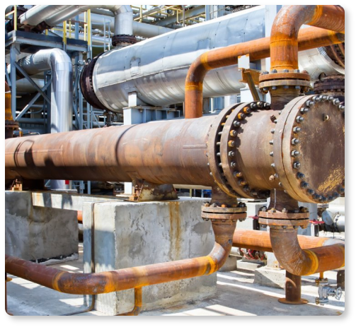
Shell-and-Tube (STHE): Known as the industrial “workhorse,” this design has been the backbone of heavy industry for over a century. Picture a bundle of hundreds or even thousands of parallel tubes, each about the diameter of your thumb, enclosed within a large cylindrical shell that might be several meters in diameter. Baffles—perpendicular metal plates with carefully designed openings—guide the fluid flow on the shell side and provide crucial structural support to prevent the tubes from vibrating themselves to destruction. One fluid flows through the inside of the tubes while another flows across the outside, separated only by the tube walls where heat transfer occurs.
Its robust nature makes it the standard for high-pressure and high-temperature applications. Need to handle steam at 100 bar pressure? Shell-and-tube can do it. Working with fluids at 500°C? Shell-and-tube won’t flinch. The design’s versatility is remarkable—by adjusting the number of tubes, their diameter, length, and arrangement, engineers can scale these units from the size of a small desk to massive installations weighing over 100 tonnes.
Double-Pipe (Hairpin): Consisting of concentric pipes often bent into a U-shape resembling a hairpin (hence the name), these are the elegant simplicity of heat exchanger design. Imagine a pipe within a pipe, doubled back on itself. One fluid flows through the inner pipe while the other flows in the annular space between the inner and outer pipes. These are ideal for scenarios involving high pressures—some units operate at pressures exceeding 400 bar—or when a significant temperature cross is required (more on this thermal acrobatics later). Their main limitation? Surface area. For large duties, you’d need many hairpins in parallel, which can become unwieldy.
2. Plate and Extended Surface
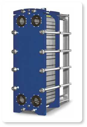
Plate Heat Exchangers (PHE): If shell-and-tube exchangers are the sturdy workhorses, plate heat exchangers are the thoroughbreds—sleek, efficient, and precisely engineered. These consist of a stack of thin corrugated stainless steel plates, each pressed with intricate chevron or herringbone patterns, sealed by elastomeric gaskets or welds, and compressed between massive end frames. The corrugations serve a dual purpose: they create turbulence (which dramatically enhances heat transfer) and provide structural rigidity to withstand pressure.
They generate high turbulence even at low flow velocities and offer immense surface area in a remarkably small footprint—a plate exchanger can provide the same thermal duty as a shell-and-tube unit in one-fifth the volume and one-third the weight. Walk into a modern dairy processing plant, and you’ll see these compact silver stacks handling everything from pasteurization to cooling, their modular nature allowing plant operators to simply add or remove plates to match seasonal production changes.
However, they are limited by the pressure and temperature capabilities of their gasket materials. Standard EPDM or Nitrile gaskets typically max out around 150°C and 25 bar. Push beyond these limits, and you need fully welded or brazed plates, which sacrifice the modularity that makes gasketed plates so attractive.
Extended Surface: Common in air-conditioning, automotive radiators, and gas cooling, these units use fins attached to tubes or plates to dramatically increase the surface area available for heat transfer. Think of the fins as force multipliers—a bare tube might have one square meter of surface area, but add densely packed aluminum fins and that same tube suddenly offers twenty square meters. This is crucial when one fluid (typically air or another gas) has poor heat transfer characteristics. The fins compensate by providing more area for the reluctant gas molecules to exchange their thermal energy.
Material Matters
Engineers must meticulously select materials—ranging from mundane Carbon Steel (the workhorse alloy for benign services) and Stainless Steel (for corrosive environments or food applications) to exotic Titanium (for seawater and aggressive chlorides), Nickel alloys (for extreme temperatures and corrosion), and even Graphite (for ultra-corrosive acids)—based on corrosion resistance, operating temperatures, and, of course, cost. A titanium plate heat exchanger might cost five times more than its stainless steel counterpart, but if it lasts thirty years in a seawater application where stainless would fail in five, the economics become compelling.
Furthermore, the choice between welded and gasketed joints is a critical safety decision regarding leakage risks and pressure containment. Welded construction offers the ultimate in leak-tightness but eliminates the ability to mechanically clean between plates. Gasketed designs allow maintenance but introduce potential leak paths. The engineer must weigh these trade-offs against the specific application requirements.
Classification: Organizing the Options
To navigate the complex world of thermal engineering, heat exchangers are classified by their structure, phase characteristics, and flow arrangement—creating a taxonomy that helps engineers quickly narrow the field from thousands of possible configurations to a handful of viable candidates.
Shell & Tube: Used for single-phase (all liquid or all gas) or two-phase transfer (e.g., condensers where vapor becomes liquid, or reboilers where liquid becomes vapor). They often utilize mixed flow arrangements called multipass designs—where tube-side fluid makes multiple passes through the exchanger, zigzagging back and forth to increase residence time and heat transfer. They are built for high-stress environments and can be found in every major industrial sector from petrochemicals to power generation.
Plate (PHE): Primarily for liquid-liquid transfer in true counterflow arrangements, where hot and cold fluids flow in precisely opposite directions, maximizing the temperature difference at every point and thus maximizing efficiency. They are the go-to for food and pharmaceutical industries due to sanitary designs with smooth surfaces and no dead zones where bacteria might hide, as well as general heat recovery applications where their compactness saves valuable plant floor space.
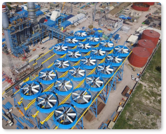
Air-Cooled (ACHE): These gas-liquid units use crossflow arrangements where one fluid flows perpendicular to the other—typically ambient air flowing across finned tubes containing the process fluid. They are vital in petrochemical industries where cooling water is scarce or environmental regulations restrict water usage. Picture the massive arrays of finned tubes you see at refineries, with fans the size of helicopter rotors forcing air across them. They trade the superior heat transfer of water cooling for the independence from water supplies.
Compact (Plate-Fin): These gas-gas units offer extraordinarily high surface area density—up to 5,000 square meters of surface area per cubic meter of volume. They are essential in aerospace applications (cooling jet engine air), cryogenics (liquefying natural gas or separating air into oxygen and nitrogen), and anywhere weight and volume are at a premium. Their intricate fin structures are often made from aluminum or stainless steel, brazed together in massive furnaces to create a monolithic block.
The Engineering Logic: Selection and Trade-offs
Designing a thermal system is a multi-variable optimization process that would make even seasoned mathematicians reach for their calculators. It is a balancing act between thermodynamics (getting the heat transferred), hydraulics (moving the fluids without excessive pressure drop), and economics (doing it all affordably).
The Thermo-Hydraulic Trade-off
This is the golden rule of heat exchanger design, the fundamental tension every engineer must resolve: Higher flow velocities increase the heat transfer coefficient (better performance, smaller equipment) but also increase the pressure drop (higher pumping costs, more powerful pumps, greater operating expenses).
Imagine you’re trying to wash heat off a surface using a fluid stream. A lazy, slow-moving stream barely disturbs the thermal boundary layer—that thin film of stagnant fluid clinging to the surface that acts like thermal insulation. But blast that surface with a high-velocity jet, and you scrub away that boundary layer, exposing fresh, cooler fluid to the hot surface and dramatically improving heat transfer. The catch? Moving fluid at high velocity requires significant pressure, and maintaining that pressure requires energy—energy that costs money every hour of every day the plant operates.
A successful design maximizes thermal effectiveness (extracting as much heat as possible) while staying within allowable pressure limits (typically specified by the pump capabilities or the allowable pressure drop budget for the entire piping system). Engineers use sophisticated software to explore thousands of configurations, seeking that sweet spot where performance and pressure drop are optimally balanced.
Operational Constraints
Fluid Properties: Dirty or fouling fluids—those containing suspended solids, polymerizing compounds, or biological growth—should be routed through the tube side of a Shell-and-Tube unit to allow for mechanical cleaning with rotating brushes or high-pressure water jets. You can’t easily clean the shell side without disassembling the entire unit. Alternatively, wide-gap Plate exchangers with channel spacings of 5-10mm (versus the typical 2-4mm) can be used, where the wider passages are less prone to blockage and easier to clean.
Viscosity: For highly viscous fluids—think heavy crude oil at room temperature with the consistency of molasses, or polymer melts flowing like honey—Plate Heat Exchangers are preferred because their corrugated geometry induces turbulence more easily than the straight tubes of tubular designs. Turbulence is critical with viscous fluids because achieving turbulent flow improves heat transfer coefficients by orders of magnitude compared to laminar flow.
Temperature Cross: If the outlet temperature of the hot fluid is lower than the outlet temperature of the cold fluid—a configuration called “temperature cross” that seems to defy intuition—counterflow units (like Hairpin or PHE) are required. Single-pass Shell-and-Tube units are generally unsuitable here because their mixed flow patterns cannot achieve the necessary temperature approach. This constraint often arises in heat recovery applications where you’re trying to extract every last joule of thermal energy.
Cost and Scalability
Total cost analysis must include both CAPEX (capital expenditure: materials, fabrication, shipping, installation) and OPEX (operating expenditure: energy for pumping, maintenance, eventual replacement). Plate exchangers offer modular scalability—production increases by 20%? Simply add more plates to the existing frame. Shell-and-Tube units are fixed once built—to increase capacity, you need an entirely new unit or a parallel installation.
Generally, for low-pressure duties (below 16 bar), PHEs are more economical, offering better thermal performance per dollar invested. But as pressure rises, the thick plates and robust frames required push costs up, and the rugged simplicity of tubular designs becomes economically attractive. At extreme pressures (50+ bar), shell-and-tube construction often becomes the only viable option.
Core Functional Requirements
Beyond efficiency and economics, industrial heat exchangers must satisfy strict functional requirements that separate adequate designs from excellent ones:
Safety: Leak prevention is paramount. A leak isn’t just an efficiency loss—it can mean toxic chemical release, fire hazards, or catastrophic pressure vessel failure. Designs must withstand internal pressures (including pressure surges during startups), thermal shock (when cold fluid suddenly enters a hot exchanger, or vice versa, creating severe thermal stresses), and corrosive chemical environments that can eat through metal over time. Multiple barriers, pressure relief systems, and conservative safety factors are standard practice.
Reliability: The unit must remain stable during startups, shutdowns, and load variations—the thermal cycling that causes metal to expand and contract, potentially leading to fatigue failures after thousands of cycles. Issues like flow-induced vibration must be engineered out through proper baffle spacing and tube support; vibration is the silent killer of heat exchangers, capable of sawing through metal tubes through microscopic back-and-forth movement over months or years.
Code Compliance: Fabrication must strictly adhere to codes like TEMA (Tubular Exchanger Manufacturers Association, the bible for shell-and-tube design) and ASME (American Society of Mechanical Engineers, setting pressure vessel standards) to ensure quality and insurability. No insurance company will cover a plant with non-code equipment, and no engineer will stake their professional license on substandard fabrication.
Maintainability: The design must allow access for cleaning—whether that means removable tube bundles, opening gaps between plates, or provisions for chemical cleaning circulation. It must provide appropriate nozzles (for connections), lifting lugs (for crane handling), and documentation (drawings, data sheets, maintenance procedures). A brilliant thermal design that cannot be maintained is worthless; it will eventually foul, fail, and be replaced with something more practical.
The Engineer’s Checklist
For those embarking on a selection process, rigorous data collection is the first step and the foundation of all subsequent work. An engineer cannot proceed without defining:
Fluid Properties: Density (affecting pressure drop calculations), viscosity (determining flow regime and heat transfer coefficients), thermal conductivity (affecting the resistance to heat flow), and specific heat (determining how much energy is needed to change the fluid’s temperature). Even small errors in these properties can lead to undersized or oversized equipment.
Thermodynamic State: Inlet and outlet temperatures for both fluids (defining the duty and approach temperatures), operating pressures (affecting design pressure ratings and fluid properties), and phase (liquid, vapor, or two-phase, each requiring different correlations and design approaches). A fluid that’s liquid at atmospheric pressure might vaporize under vacuum conditions, completely changing the heat transfer mechanisms.
Constraints: Maximum allowable pressure drop (often dictated by available pump head or system hydraulics), fouling factors (safety margins accounting for the inevitable buildup of deposits over time), space limitations (can you fit a 6-meter-long shell-and-tube, or do you need a compact plate exchanger?), and maintenance access requirements (can you pull a tube bundle in this location, or do you need a design that can be cleaned in place?).
By balancing these complex physical realities with economic and safety constraints, by running iterative calculations that explore the design space, by applying decades of accumulated engineering wisdom encoded in design standards and software, engineers ensure that heat exchangers continue to serve as the reliable heart of modern thermal management systems.
These silent titans work around the clock, year after year, moving thermal energy with elegant efficiency. They are the unsung heroes of industrial civilization—not glamorous, rarely seen by the public, but absolutely essential. The next time you enjoy ice-cold air conditioning on a sweltering day, or benefit from the countless products refined and processed with precise temperature control, spare a thought for the heat exchanger quietly doing its job somewhere in the background, moving heat from where it isn’t wanted to where it’s needed, one thermal transaction at a time.
Keep Learning
Independent Frequency and Power Control in Induction Inverters: Turning Frequency Back Into a Process Variable
Key Takeaways Frequency as a process variable: Independent frequency and power control decouples resonance supervision from kW regulation, letting engineers set frequency based on process physics rather than control mechanics. Measurable validation: Prove independent control with three commissioning tests—fixed-frequency power steps, fixed-kW frequency sweeps, and coupling variation stability. Production consistency: Stable frequency improves recipe portability, reduces hidden process changes, and mak......
Simultaneous Dual-Frequency Induction Heating: When One Frequency Forces the Wrong Compromise
Key Takeaways One frequency, one compromise: When geometry demands both deep bulk heating and controlled surface gradients simultaneously, a single frequency forces an unacceptable trade-off—dual-frequency widens the process window. Give each channel a role: Assign the lower frequency to bulk penetration and the higher frequency to surface shaping. Structured recipe development follows naturally from this separation. Validate with metrics, not opinions: Dual-frequency is justified only when controlled......
Power Supplies by Application Family: Joining, Mass Heating, and Strip Processing
Key Takeaways Joining operations (brazing, soldering, bonding) demand higher frequencies and matching flexibility to handle variable coil coupling and precision surface heating. Mass heating lines (billets, bars, slabs) prioritize continuous duty, efficiency, and ruggedness at high power levels with multi-coil zone control. Strip processing requires architectures that separate control electronics from high-frequency inverter modules to cope with harsh installation environments. Specifying only kW and ......
Simultaneous Dual-Frequency Induction Power: When One Frequency Forces the Wrong Compromise
Key Takeaways Dual-frequency is justified by robustness, not complexity: It should only be adopted when a single frequency forces an unacceptable compromise between surface and bulk heating requirements. Give each frequency a defined role: Assign the lower frequency to bulk heating/penetration and the higher frequency to surface shaping—then develop recipes one variable at a time. The combining network is the engineering center of gravity: Frequency-selective coupling paths, thermal rating for worst-c......
Applying Induction Power Supplies in the Real World: Constraints That Decide Uptime and Quality
Key Takeaways Application constraints dominate real-world performance: Two induction systems with identical kW ratings can behave very differently depending on cable length, cooling water temperature, dust levels, and fixture repeatability. Design for drift, not for perfect day one: Coils deform, filters clog, sensors drift, and connectors loosen under thermal cycling. Baseline monitoring during commissioning is essential. Mechanical repeatability often beats control complexity: Improving fixturing an......
Medium- and High-Frequency Transformers in Induction Systems: Design Drivers Engineers Should Actually Care About
Key Takeaways Not Passive: Transformers set the electrical operating point for the entire induction station—coil voltage, current, capacitor stress, and inverter margin all depend on transformer choice. Frequency Effects: At higher frequencies, winding losses and stray capacitance dominate; a transformer that looks fine on turns ratio can fail a duty-cycle test if loss distribution is wrong. Placement Matters: Moving the transformer and capacitor bank closer to the coil reduces high-frequency loop len......