
The Art of Thermal Design: Where Physics Meets Economics
12 min
- The Core Philosophy: The Great Trade-Off
- The Design Methodology: A Logical Sequence
- When Good Designs Fail: Common Pitfalls
- The Role of Modern Computing
- The “Operational Cost”: Pressure Drop
- Conclusion: Managing the Unknown
- The Engineer’s Checklist
- FAQ
Heat exchangers are the unsung workhorses of the modern world. From the radiator cooling your car’s engine to massive industrial towers refining crude oil, these devices perform a critical function: moving energy from one fluid to another.
But how do engineers decide exactly how big, how long, or how complex these devices need to be? This process is called Thermal Design. It is far more sophisticated than simply “making it big enough.” It is a high-stakes balancing act that merges thermodynamics, fluid mechanics, and brutal economic reality.
The Core Philosophy: The Great Trade-Off
At its heart, thermal design is an iterative process of compromise. The fundamental law of heat exchanger engineering is simple but unforgiving: Performance comes at a price.
To achieve high Thermal Effectiveness (transferring the maximum amount of heat), you generally need a larger surface area. Think of it like a radiator in your home—the more fins and tubes it has, the more efficiently it can warm the room. However, a larger unit introduces three penalties:
1. Higher Capital Cost: More metal and larger footprints cost more money. A shell-and-tube exchanger the size of a school bus doesn’t just require tons of stainless steel; it needs massive foundations, heavy-duty cranes for installation, and potentially an expanded building to house it.
2. Increased Weight: A problem for structural support and transport. Industrial heat exchangers can weigh 50 to 100 tons when fully assembled. Every additional ton means stronger support structures, more expensive shipping, and potential limits on where the unit can even be installed.
3. Higher Pressure Drop: Pushing fluid through a vast network of tubes requires more pumping power. It’s like trying to drink a thick milkshake through an extremely long, narrow straw—you need more suction. In industrial terms, this means bigger pumps, higher electricity bills, and more maintenance.
The engineer’s goal is to find the “sweet spot”—a design that meets the Heat Duty (the required energy transfer) without bankrupting the operator on construction costs or electricity bills for pumps.
Key Concept: Approach Temperature
This is the temperature difference between the hot and cold fluids as they exit the unit. Imagine you’re heating water with hot steam. In a perfect world, the steam would cool down to exactly the same temperature as the heated water—transferring every last bit of energy. But this perfection requires an infinitely large exchanger.
A “tight” approach (where the fluids leave at almost the same temperature—say, differing by only 5°C) is thermally efficient but requires a massive, expensive surface area. A “loose” approach (perhaps a 20°C difference) saves money on equipment but recovers less waste energy. In energy-intensive industries like petrochemicals, this choice directly impacts profitability. A refinery processing 100,000 barrels per day might save millions annually by recovering just a few more percentage points of waste heat.
The Design Methodology: A Logical Sequence
Designing a heat exchanger isn’t a straight line; it’s a loop. While every engineer has their own style, the standard procedure follows a universal logic.
Step 1: Data Collection
It begins with the constraints. What are the flow rates? What are the inlet and outlet temperatures? What are the viscosity and density of the fluids? This stage is deceptively critical. A viscosity measurement taken at the wrong temperature can lead to a design that’s undersized by 30% or more. Fluids behave very differently when they’re hot versus cold—honey flows like water when heated, and water becomes sluggish when it approaches freezing.
Step 2: Configuration Selection
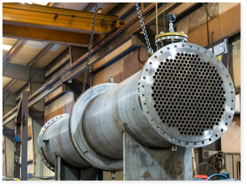
The engineer chooses the “hardware” type—usually a Shell-and-Tube, Plate, or Compact exchanger—based on pressure limits and how “dirty” the fluids are.
Shell-and-tube exchangers are the workhorses—robust, easy to clean, and capable of handling extreme pressures (up to 100 bar or more). Plate exchangers are compact and efficient but can’t handle particles or extreme temperatures. Compact exchangers, like those in aircraft or automobiles, pack enormous surface area into tiny volumes using intricate fin geometries—but they’re expensive and prone to clogging.
Step 3: Estimation
We assume a preliminary Overall Heat Transfer Coefficient (U). This is an educated guess derived from experience or standard tables. For water-to-water exchange, U might be around 1000–3000 W/m²·K. For gas-to-gas, it plummets to 30–60 W/m²·K because gases are poor conductors. This number is the designer’s starting point—a provisional answer that will be refined through iteration.
Step 4: Sizing (The Math)
We calculate the required surface area (A) using the fundamental heat load equation:
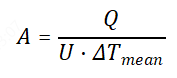
Where Q is the heat duty (the total energy that must be transferred, in watts) and ΔTmean is the average temperature difference between the hot and cold fluids. This average isn’t always simple—depending on the flow arrangement, engineers use either the Log Mean Temperature Difference (LMTD) or the more flexible ε-NTU method for complex configurations.
Step 5: Iteration
This is the reality check. The engineer calculates the actual pressure drop and wall temperatures for the selected size. If the pressure drop is too high (say, 2 bar when only 0.5 bar is acceptable), or the unit is too big to fit in the available space, they adjust the geometry—perhaps changing tube diameter from 19mm to 25mm, or increasing baffle spacing from 200mm to 300mm—and repeat the process.
Sometimes, a design goes through five or six iterations before it satisfies all constraints simultaneously. This is where experience separates novices from veterans.
When Good Designs Fail: Common Pitfalls
Even a mathematically perfect design on paper can fail in the physical world. Here are the distinct challenges engineers must solve.
1. The “Temperature Cross” Paradox
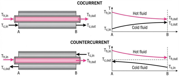
A temperature cross occurs when the cold fluid’s outlet temperature is actually higher than the hot fluid’s outlet temperature. Picture this: you’re trying to heat cold oil to 150°C using hot water that starts at 130°C. Thermodynamically, this is impossible in a simple setup—heat won’t flow “uphill.”
In many standard setups (like co-current flow, where both fluids travel in the same direction), this is thermodynamically impossible because the “driving force” disappears. The temperature difference that pushes heat from hot to cold simply evaporates.
The Fix: Engineers must switch to a Counter-Current design (where fluids flow in opposite directions, maximizing the temperature difference throughout the exchanger) or connect multiple shell-and-tube units in a series to maintain the necessary temperature gradient. Sometimes, they’ll use a 1-2 or 2-4 shell-and-tube configuration—these are hybrid arrangements where the tube-side fluid makes multiple passes while the shell-side makes one.
2. Fluid Laziness (Bypass and Maldistribution)
Fluids always follow the path of least resistance. If there is a gap between the tube bundle and the shell wall—even a gap of just a few millimeters—the fluid will “bypass” the tubes entirely, flowing uselessly through the gap like water finding a shortcut around a dam. This can reduce effectiveness by 20–40%.
Similarly, in plate exchangers, if the inlet manifold is poorly designed, most of the flow might concentrate in just a few channels while others sit nearly stagnant. This is called maldistribution, and it’s the silent killer of thermal performance.
The Fix: We install Sealing Strips—physical barriers welded or bolted along the shell that force the fluid back into the tube bundle, preventing ineffective bypass flow. For maldistribution, engineers redesign inlet headers or add flow distributors that spread the fluid evenly across all channels.
3. The Triple Threat: Pressure, Fouling, and Vibration
Pressure Drop: If the resistance is too high, pumps fail—or more precisely, they consume so much power that operating costs become unsustainable. A poorly designed exchanger might require a pump that draws 500 kW continuously. Over a year, that’s 4.4 million kWh—potentially hundreds of thousands of dollars in electricity. The solution is often increasing tube diameter (less friction per meter) or baffle spacing (fewer turns and contractions).
Fouling: Over time, dirt accumulates on tubes, acting as an insulator. In cooling water systems, mineral deposits (scale) build up like limescale in a kettle. In oil refineries, carbon residues form crusty layers that choke heat transfer. Engineers add “Fouling Factors” (essentially planning for degradation by designing in 15–30% extra surface area) to account for this inevitable accumulation. Cleaning is scheduled annually or biannually, where the exchanger is taken offline and tubes are mechanically scraped or chemically washed.
Vibration: High-velocity flow can cause tubes to rattle and rupture—a phenomenon called flow-induced vibration. When fluid rushes across tube bundles at high speed, it creates alternating vortices that can resonate with the tubes’ natural frequency. This is how a flute makes sound, and it’s catastrophic in a heat exchanger. Tubes crack at welds, leading to leaks and contamination. Support plates must be added every meter or so to dampen these vibrations and prevent fatigue failure.
The Role of Modern Computing
Today, engineers use advanced software (like HTRI, Aspen EDR, or HTFS) to handle the complex calculus of thermal design. These programs solve thousands of equations simultaneously—predicting heat transfer, pressure drop, tube vibration risk, and even the optimal baffle cut percentage.
They allow for Sensitivity Analysis—running “what-if” scenarios to see how a 10% surge in flow rate might affect vibration risks, or how winter versus summer cooling water temperatures might change performance. A designer can test 50 different configurations in an afternoon, something that would have taken weeks with hand calculations in the pre-computer era.
However, the computer is only a tool. A human engineer must validate the output against field data and physical intuition to ensure that “garbage in” didn’t lead to “garbage out.” Software can’t tell you that the refinery plans to switch from light crude to heavy crude next year, changing the fouling characteristics entirely.
The “Operational Cost”: Pressure Drop
It is vital to view Pressure Drop as an energy currency. Every unit of pressure lost due to friction or turbulence inside the exchanger must be restored by a pump or fan.
Tube-Side: Friction losses are predictable. Standard correlations (like Darcy-Weisbach) give accurate estimates based on fluid velocity, tube roughness, and length.
Shell-Side: This is chaotic. As fluid expands, contracts, and turns around baffles, it creates turbulence—beneficial for mixing and heat transfer, but murderous for pressure. A single baffle might introduce a pressure drop of 0.1 bar. With 20 baffles, that’s 2 bar total. While turbulence improves heat transfer coefficients (sometimes doubling them), it drastically increases drag.
Since pumping power is proportional to pressure drop and flow rate (𝑃𝑜𝑤𝑒𝑟∝𝛥𝑃⋅ṁ ), an overly conservative design with high resistance will bleed money through electricity costs over its lifespan. Over 20 years, the operational cost can exceed the capital cost by a factor of three or more.
Conclusion: Managing the Unknown
In the real world, “nominal conditions” are a myth. Feed compositions fluctuate—refineries process different crude blends, and chemical plants adjust production rates. Seasons change, meaning cooling water temperatures swing from 5°C in winter to 25°C in summer. Furthermore, the empirical correlations used to predict heat transfer have error margins of ±20%.
To handle this, modern engineering moves beyond blindly adding safety margins. We use statistical analysis to determine a Confidence Level—ensuring the equipment works 90% or 95% of the time without being wastefully expensive. Rather than designing for the absolute worst-case scenario (which might occur only once every five years), we design for the 95th percentile condition. This pragmatic approach balances reliability with cost-effectiveness.
The Engineer’s Checklist
If you are evaluating a thermal design, ask these five questions:
• ☐ Properties: Are viscosity and thermal conductivity accurate at the operating temperature? (Properties at 20°C are worthless if the fluid operates at 200°C.)
• ☐ Velocities: Is the flow fast enough to scour away dirt (typically >1 m/s for liquids), but slow enough to prevent vibration and erosion (usually <3 m/s)?
• ☐ Leakage: Have sealing strips been used to block bypass lanes between the tube bundle and shell?
• ☐ Thermodynamics: Is there a temperature cross, and does the flow arrangement support it?
• ☐ Safety: Is the margin sufficient to cover data uncertainties (±20% on correlations) and future fouling (15–30% degradation over time)?
Thermal design is ultimately an exercise in humility. No matter how sophisticated the analysis, the first startup of a new exchanger always reveals surprises—a hot spot here, an unexpected vibration there. The best engineers learn from these lessons and feed them back into future designs, continuously refining the art of balancing physics with economics.

FAQ
Q1: Why do larger heat exchangers cost more than just the materials?
A: Beyond the metal itself, larger units require stronger structural foundations, specialized cranes for installation, expanded building space, and heavier shipping logistics. A 50–100 ton exchanger isn't just expensive to build—it's expensive to move and support.
Q2: What is a "temperature cross" and why is it a problem?
A: A temperature cross occurs when the cold fluid's outlet becomes hotter than the hot fluid's outlet—thermodynamically impossible in simple setups. The solution is switching to counter-current flow (fluids travel opposite directions) or connecting multiple units in series to maintain proper temperature gradients.
Q3: How does fouling affect long-term heat exchanger performance?
A: Over time, mineral deposits, dirt, and carbon residues accumulate on tubes like limescale in a kettle, acting as insulators and reducing heat transfer. Engineers design in 15–30% extra surface area as a "fouling factor" and schedule annual or biannual cleanings to maintain efficiency.
Keep Learning
Power Supplies by Application Family: Joining, Mass Heating, and Strip Processing
Key Takeaways Joining operations (brazing, soldering, bonding) demand higher frequencies and matching flexibility to handle variable coil coupling and precision surface heating. Mass heating lines (billets, bars, slabs) prioritize continuous duty, efficiency, and ruggedness at high power levels with multi-coil zone control. Strip processing requires architectures that separate control electronics from high-frequency inverter modules to cope with harsh installation environments. Specifying only kW and ......
Simultaneous Dual-Frequency Induction Power: When One Frequency Forces the Wrong Compromise
Key Takeaways Dual-frequency is justified by robustness, not complexity: It should only be adopted when a single frequency forces an unacceptable compromise between surface and bulk heating requirements. Give each frequency a defined role: Assign the lower frequency to bulk heating/penetration and the higher frequency to surface shaping—then develop recipes one variable at a time. The combining network is the engineering center of gravity: Frequency-selective coupling paths, thermal rating for worst-c......
Applying Induction Power Supplies in the Real World: Constraints That Decide Uptime and Quality
Key Takeaways Application constraints dominate real-world performance: Two induction systems with identical kW ratings can behave very differently depending on cable length, cooling water temperature, dust levels, and fixture repeatability. Design for drift, not for perfect day one: Coils deform, filters clog, sensors drift, and connectors loosen under thermal cycling. Baseline monitoring during commissioning is essential. Mechanical repeatability often beats control complexity: Improving fixturing an......
Medium- and High-Frequency Transformers in Induction Systems: Design Drivers Engineers Should Actually Care About
Key Takeaways Not Passive: Transformers set the electrical operating point for the entire induction station—coil voltage, current, capacitor stress, and inverter margin all depend on transformer choice. Frequency Effects: At higher frequencies, winding losses and stray capacitance dominate; a transformer that looks fine on turns ratio can fail a duty-cycle test if loss distribution is wrong. Placement Matters: Moving the transformer and capacitor bank closer to the coil reduces high-frequency loop len......
Load Matching in Induction Heating: Designing for Stability, Efficiency, and Real-World Variation
Key Takeaways Dynamic Load: Induction heating loads are not fixed—coupling, material properties, and temperature all shift impedance during operation, making matching a continuous design challenge. Q Factor Matters: High-Q loads can produce large circulating currents and capacitor stress even at modest delivered kW; design for the worst-case kVA, not just power. Discrete Ranges Win: Transformer taps and capacitor steps that cover discrete matching ranges outperform a single broad-range configuration f......
Induction Power Supply Topologies: A Practical Guide to Converters, Inverters, and Matching Networks
Key Takeaways Point 1: Topology choices determine input power quality, response speed, detuning tolerance, and physical constraints in real installations. Point 2: Converter options (diode vs SCR vs active front end) significantly affect partial-load power factor and plant power quality. Point 3: Inverter types (voltage-fed vs current-fed) dictate protection philosophy and sensitivity to load changes, while matching network placement is driven by cable length limitations. Induction heating power suppl......