
Keeping Your PCBs Cool : Practical Heatsink Strategies for Better Thermal Performance
13 min
- Exploring Popular PCB Heatsink Types:
- Key Materials in Effective PCB Heatsinks
- Advanced Thermal Solutions Beyond Traditional Heatsinks
- Implementing Heatsink Solutions in Your PCB Design
- Frequently Asked Questions (FAQ)
The current PCBs are becoming insane, and hence the cooling of PCBs is absolutely necessary. Large power components such as CPUs, GPUs, SOCs, voltage regulators, and LED drivers all ooze heat as a side-effect of their operation. Therefore, as an example, it is common to have CPUs, GPUs, or SOCs with their own heatsink, or boards that are extremely dense or contain power items such as motors, power transistors, amplifiers, regulators, etc., can end up in hot spots. A small PCB may become hot whena lot ofh current is passed through the traces.
Unless you get rid of that heat, you are losing reliability and lifespan. The standard guideline is that each 10 °C increment in uptake is about doubling the failure rate. And with proper management of the heat, you can prevent over half of all failures of electronic systems. In other words, when you leave your board too hot, it becomes a baked computer, performance is reduced, parts are throttled or work off, and solder joints may fail due to the thermal load (thermal cycling). And in the worst case, you are dealing with thermal runaway: the heat generation increases faster than the heat can dissipate, and thus the circuits are the start of a runaway failure.
Heat Generation and Heat Control:
Typical “heating elements” on a PCB include high-power ICs (CPUs, GPUs, MCUs), power converters and regulators, RF amplifiers, LED arrays, and even tight power traces. Any component driving significant current or dissipating several watts will produce waste heat. Packing more chips into a small board increases heat generation in confined areas. So designers must watch out for component density. Even though many PCBs use fire-resistant FR‑4, its thermal conductivity is low (0.25 W/m·K), so heat doesn’t escape easily through the substrate itself.
If heat isn’t managed, expect higher failure rates and reduced life. Elevated temperatures accelerate chemical and mechanical wear. For every 10°C hotter a chip runs, its mean lifetime drops by roughly half. Overheated boards can suffer immediate issues like voltage regulator shutdowns or even PCB warping.
Exploring Popular PCB Heatsink Types:
Extruded Aluminum Heatsinks.
Extruded aluminum heatsinks are simply created by forcing hot aluminum through a die to draw these long, uniform fin profiles. It results in a batch of closely packed fins with good base-to-fin heat transfer and rather reliable quality. They are cheap and lightweight, so most of the electronics projects fail with them, particularly when the power consumption is medium to high.
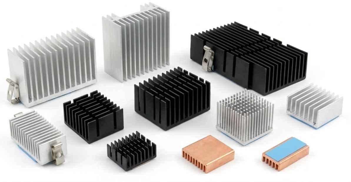
Extrusions may be tailored to straight fin, slanted fin, or pin-fin geometry. Straight-fin designs provide solid cooling in a constant footprint, whereas pin-fin extrusions allow the air to flow in any direction when the airflow paths are not apparent. A ton of extruded heatsinks is anodized to increase resistance to corrosion and provide a minor thermal radiation advantage. Summary: They are good players at a fair pric,e provided that you have both the board space and the height to accommodate them.
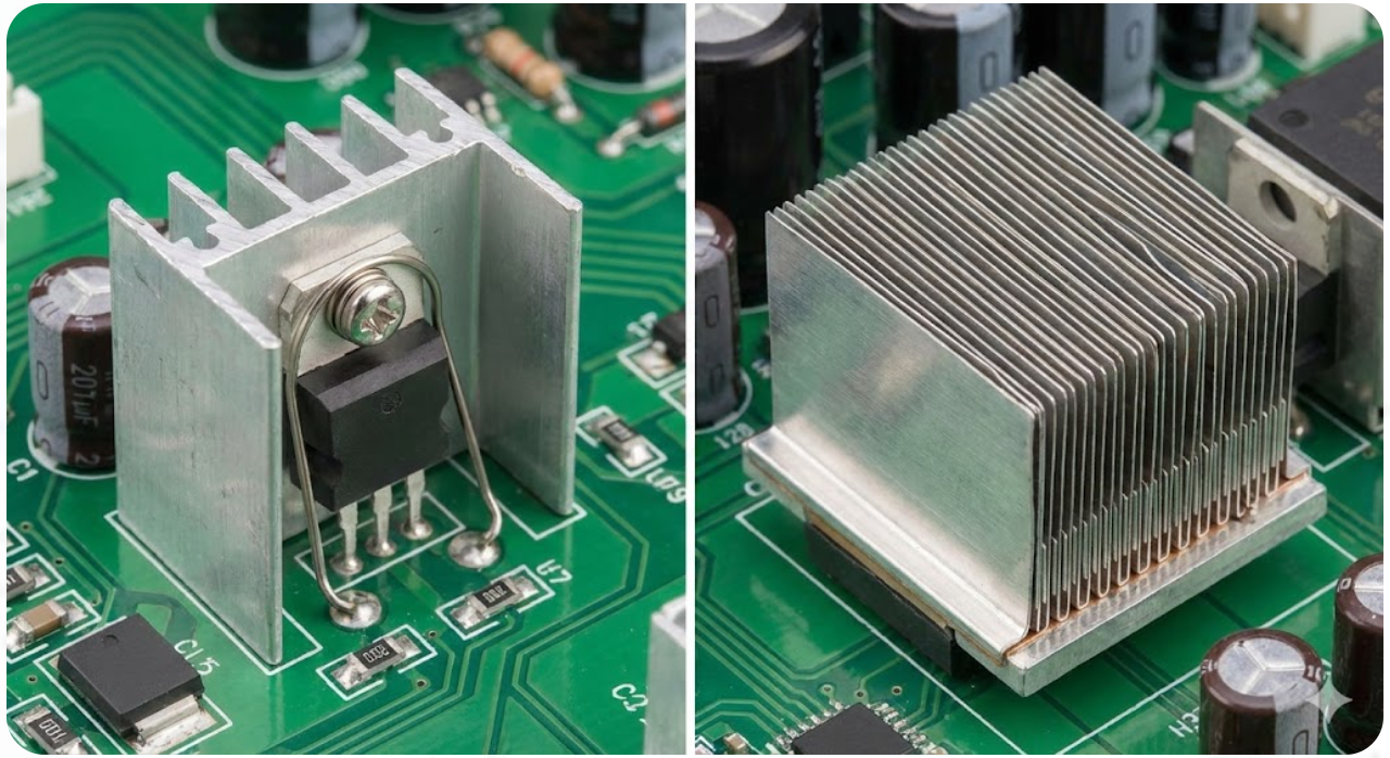
Stamped and Folded -Fin Heatsinks.
The fins are made out of stamped heatsinks cut and bent out of thin sheets of aluminum. They are inexpensive and small, and in many cases have spring clips that allow them to simply be clamped to components such as TO-220 or TO-247. Although bent or twisted fins assist in pushing air, stamped designs are primarily of low to moderate power, as the height of the fin is simply not that large.
Folded-fin heatsinks are high-density and compact. Corrugated metal strips are folded and welded or bonded onto a base plate by the manufacturers to provide heights of approximately 12 inches. Such variations as wavy or lanced fins contribute to the increased movement of air. You will find them in telephone equipment and in high-density PCB assemblies where you have space to spare, but require higher cooling than stamped components can provide.
Bonded- Fin and Heat-Pipe Solutions.
At too high a power, extrusions cannot keep pace; bonded-fin heatsinks come in. Fat individual fins are pasted or welded onto a solid substrat,soch that you can have an array of huge fin heatsinks so dense. The most popular trick to maintain the performance without adding excessive weight is mixing of materials, i.e., copper fins on an aluminum base. They are the preferred options when using high-power or forced-air systems.
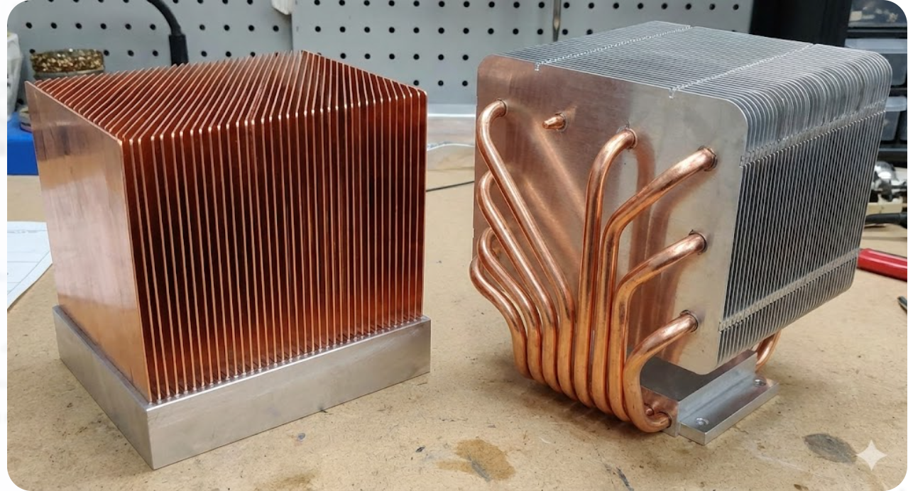
A heat-pipe-integratedd heatsink takes it even further by conducting the heat of the source to remote fins by using phase change. Embedded copper pipes conduct heat well, and thus they are ideal in the case of heavy loads such as GPUs, avionics, or lasers. They are strong, and you normally use them when the task is the largest and most challenging.
Low‑Profile Cooling Options
When space is at a premium in the vertical dimension, ultra-low profile heatsink products can be used. They are only a few millimeters high, with short fins or cross-cut designs, and most of them have pre-applied thermal adhesives that allow you to tap them on with a stick. Fine copper blocks or flat links may also conduct heat across the PCB.
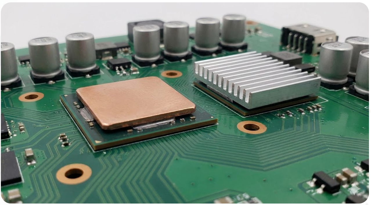
In the smallest designs, you could do away with fins and replace them with flat heat spreaders or metal-core PCBs. These are oriented at remaining small rather than overloading cooling, thus you actually need good thermal interfaces and good control of air flow.
Key Materials in Effective PCB Heatsinks
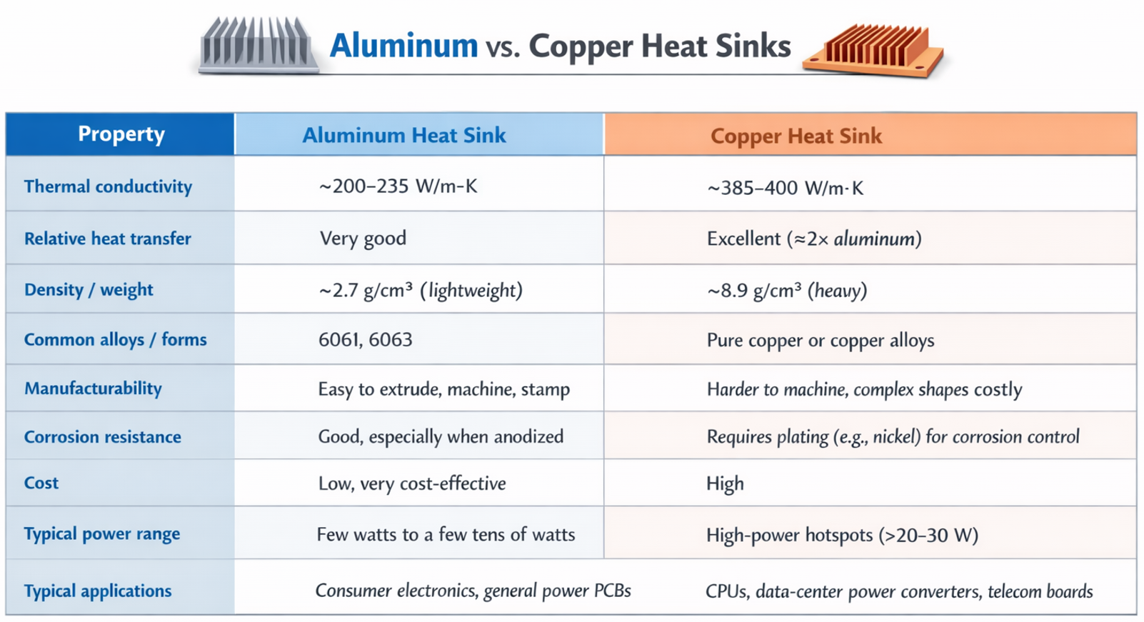
The choice of heatsink material greatly affects performance, weight, and cost. The two classic materials are aluminum and copper, each with pros and cons:
Surface Treatments and Finishes for Better Heat Transfer
How you finish a heatsink surface can also matter, especially for passive (air-cooled) boards. The main treatments are:
- Anodizing: This is an electrochemical process that thickens the natural oxide on aluminum. Anodized surfaces are more durable and have much higher thermal emissivity (ability to radiate heat) than bare metal. In fact, raw aluminum has an emissivity of 0.05, whereas a black-anodized surface is ≈0.85. The darker, rough surface means any heat radiated (infrared) is much higher. This helps in low-airflow conditions, a small sink benefits more from anodizing. For forced-air cooling, the boost in radiative cooling is less pronounced, but anodizing still adds corrosion resistance and a more robust surface.
- Plating and Coatings: Copper sinks often get nickel or tin plating to prevent oxidation and galvanic corrosion. A copper base will still perform thermally, but the thin plating keeps its surface shiny and long-lasting. Another popular finish is a black thermal paint or black anodized coating on any sink: this significantly ups emissivity, making infrared radiation stronger useful if you have little convection. Again, this is more about durability and radiation; it won’t greatly change conduction to the fins.
Emerging Materials Like Graphite and Composites
Graphite/Graphene: Highly oriented graphite or graphene sheets have in-plane thermal conductivity far above coppe. They can spread heat quickly across a plane. For example, a graphite plate under a chip can whisk lateral heat to the edges of the board. Graphite and graphene are gaining attention for “exceptional thermal conductivity” in lightweight form.
Metal-Matrix Composites (MMCs): These are alloys or composites combining metals (Al or Cu) with other materials to tune properties. Some MMCs can reach thermal conductivities up to 400–600 W/m·K while keeping density lower than pure copper. They also have a lower coefficient of thermal expansion, useful in aerospace. However, they are costly and usually reserved for special cases.
Advanced Thermal Solutions Beyond Traditional Heatsinks
The Thermal Vias and Its Heat Distributing Role.
Thermal vias are simply plated holes beneath the heat generating components that conduit heat across the board. Consider them as vertical pipes, they draw heat out of the upper copper to internal planes or the bottom layer so that it can diffuse out or be carried away by a heatsink. Rather than localizing all the heat on the pad, an effective via layout provides the board with a low-resistance path to cool off. Thermal vias can be utilized in the best case where surface-mount chips contain exposed thermal pads, such as QFNs and power ICs. Instead of a single via, we tend to put a bunch of them near each other to promote improved heat conduction.
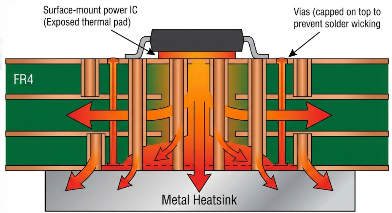
An example is a diameter of vias of about 0.3 mm with a spacing of approximately 0.8 mm. A single grid of them as small as 5 by 5 can sink the junction temperature by tens of degrees due to the presence of a heatsink on the other side when connected to the internal ground or power planes, or a heatsink on the other side. The manufacturing factor is essential. Straight through vias on the pads must be filled or capped otherwise the solder will steal them during reflow. Besides, the vias can be useful only when there is enough copper or a heatsink on the opposite side to absorb and dissipate the heat. When you hit the nail on the head, thermal vias reduce the temperatures of hot-spots by huge margins and turn the board into a two-sided heatspreader, a factor that enhances the reliability of PCBs.
Passive Cooling Elements, Copper Pours and Plane Layers.
Another passive device is the addition of an extra copper around heat sources. Full plane layers and big copper pours act as heat reservoirs and dissipate the heat laterally and contain local spikes. Connecting the pad of a power component to a large ground or power plane allows the heat to be spread across a much larger area than would otherwise be possible by keeping the component stuck on a single pad. We tend to distribute copper to hot components or connect to inner planes directly through thermal vias. Surrounding a power IC with copper can significantly reduce the temperature of the temp when it is loaded.
Full internal planes provide an additional low-resistance pathway of heat that is compatible with the vertical flow of vias. Admittedly, an increase in the copper content incurs greater weight on the board and more difficult routing, but the benefits of the heat outweigh the drawbacks. Adding additional inner copper plates and increasing the copper weight (imagine 2-3 oz instead of 1oz) increases passive spread further. It also levels thermal differences and squashes hot spots, although may not actively draw heat out. Metal-core PCBs accomplish the same gimmick on a larger scale by replacing FR4 with metal, though you can also obtain most of those benefits in standard multilayers as long as you make judicious use of copper.
Active Cooling: Fans, Heatsinks and Liquid Solutions.
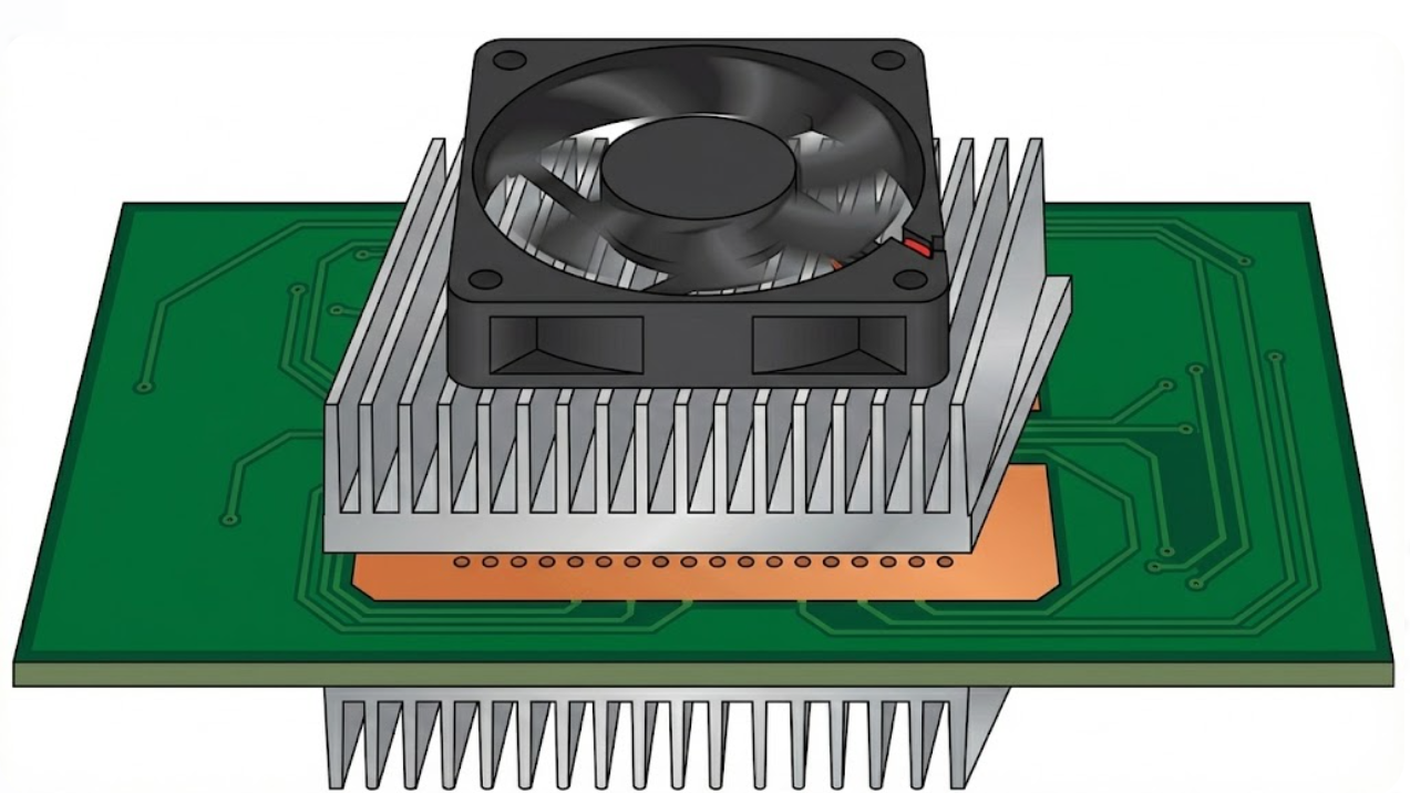
When the non-violent means are not sufficient, you have to become active. The active cool of choice is forced-air; typically a fan is added to blow air over the board or a heatsink. Even mini fans are capable of removing 20-30 degrees. Boards of high power tend to pass the air in ducts or shrouds to squeeze out extra efficiency. Disadvantages include the additional money, sound, energy consumption, and reliability loss of moving components.
Liquid cooling may be observed in insane high power spots. Cold plates or heat exchangers which are run with water can accommodate loads that are far more than air can dissipate. On daily PCBs it is however uncommon due to the complexity, weight and leak risk. It is primarily used with data centers, industrial equipment or high-performance computers. In between air and liquid designs are some designs that use heat pipes or vapour chambers within heatsinks or modules. These two-phase passive devices dissipate heat rapidly at a hot spot, between simple air and complete liquid systems.
Implementing Heatsink Solutions in Your PCB Design
Placement Rules and Attachment Methods (Clip, Adhesive, Screw)
When applying heatsinks to the board, therefore, ensure that there is adequate ventilation. Do not stuff hot parts near the wall or other sources of heat, use vents or fans instead. Moving a MOSFET nearer to the PCB edge or cutting a hole can reduce the temperature of that MOSFET significantly. When you are putting high-power parts together, then that can be counterproductive; they should be spaced. Practically, designers usually simulate airflow: even moving a component a few millimeters can reduce thermal resistance by one-fifth.
Attachment Methods: Heatsinks may be fixed either by adhesive or mechanical. Common methods include:
- Clips and Screws: Many TO‑220 or TO‑247 sinks have holes for screws. PCB-mounted studs or board clips can hold the sink.
- Thermal Adhesives/Pads: A double-sided thermal tape or epoxy can bond a heatsink to a component’s surface. This simplifies assembly and avoids board holes.
- Solderable Tabs: Some board-level sinks have flat tabs that can be soldered onto the PCB copper. This makes them effectively part of the board, but soldering requires precise reflow.
Each method has trade-offs. Clips/screws are rework-friendly but add weight. Adhesives are sleek but permanent.
Thermal Interface Materials and Gap Fillers

No heatsink, even the best one, will be able to lie flat on a chip because of little bumps on the surface. Air gets trapped inside those bumps and that is not a good heat conductor, so we use thermal interface materials (TIMs) to close those holes and maintain a solid heat path. Common TIMs include grease or paste, pads and phase-change stuff. It is aimed at driving air out, not to beat metals in conductivity.
The interface resistance can be reduced significantly by a thin, good layer of paste when compared to touching metal. Pads are less difficult to drop on, and do not thicken, but they do not conduct heat as easily as a good paste does. The selection of the correct TIM is important since the interface normally determines the effectiveness of the entire system cooling. Always follow the recommended thickness and compression by the manufacturer, particularly when the parts are not flat. In larger ones, gap fillers or adhesives with conductivity can be used- they both tolerate heat, and can be used as a joint should you require a lasting or semi-lasting bond.

Frequently Asked Questions (FAQ)
Q: Do I really need a thermal pad or paste under the sink?
A: Yes. A thin layer of thermal compound (paste) or a thermal pad between the component and the sink significantly improves heat transfer. Without it, microscopic air gaps between metal surfaces act as thermal insulators
Q: What are thermal vias, and should I add them?
A: Thermal vias are drilled-through holes under a hot pad, plated with copper, that conduct heat down into inner board layers. You should use them whenever you have a hot surface-mount IC with a thermal pad (like QFNs or power modules).
Q: Can I combine heatsinks with fans or other cooling?
A: Absolutely. Passive heatsinks are great, but adding airflow makes cooling much better. Even a small fan blowing over a finned sink can drop the temperature by 20–30°C
Q: Are there advanced PCB options beyond heat sinks?
A: Yes. Besides heatsinks and airflow, you can use specialized board materials. For example, metal-core PCBs (aluminum or copper core) wick heat through the board itself.
Popular Articles
Keep Learning
Optimizing Power Nets for Stable and Efficient High-Performance PCBs
Key Takeaways Power Nets as Systems: It is a complete copper network of planes, pours, traces, and vias built to deliver clean, stable voltage. Control IR Drop: Copper resistance causes voltage drop. Use wider traces, solid pours, or heavier copper (2 oz+) to stay within voltage tolerances. Minimize Loop Area: Place decoupling capacitors close to power pins with short, wide traces to handle fast transient currents. Scale Your Vias: A single 0.3mm via carries only 1 to 2A. High-current paths require pa......
Achieving Stable Power Delivery : Mastering PDN Impedance in High-Performance PCBs
Key Takeaways PDN impedance directly determines voltage stability under load. Keep it low and flat. Calculate your target: Z_target = (V_dd × Ripple%) / I_transient — typically single-digit milliohms. Prioritize close power-ground planes, short via connections, and strategic decoupling placement. Avoid anti-resonance peaks; a smooth curve matters more than raw capacitance. Precise manufacturing (copper thickness, dielectric control) is essential to match simulation results. There's no point in using a......
Phase Matching in High-Speed PCB Design: Achieving Signal Integrity with Precision Manufacturing
Key Takeaways Phase matching controls electrical trace length in high-speed PCBs to maintain precise signal timing and phase relationships. Even 10–15 ps skew (roughly 1–2 mm difference) at 10 Gbps can collapse eye diagrams, raise bit error rates, and cause system failures. Dynamic phase matching maintains alignment throughout the entire signal path, accounting for bends, vias, and layer transitions. USB 3.x SuperSpeed interfaces commonly target intra-pair skew below 5 mils (0.13 mm) to maintain relia......
Mastering Split Planes for Cleaner Power Delivery and Better Signal Integrity
Key Takeaways Split power planes when needed for multiple voltage domains or analog/digital isolation, but never split ground planes — always keep ground continuous for clean return paths. Avoid routing high-speed signals across splits; if unavoidable, use stitching capacitors (0.1 µF) and ensure differential pairs cross together. Place split power planes next to a solid ground layer, maintain ~10 mil moat width, and use proper decoupling near IC pins. Good split plane design significantly reduces noi......
Building Stable Power Delivery for High-Performance PCBs with Power Integrity Analysis
Key Takeaways Power integrity analysis is essential for building stable power delivery in high-performance PCBs. By maintaining low PDN impedance, optimizing decoupling capacitors, and designing robust power/ground planes with minimal voltage droop and inductance, engineers can prevent common failures such as voltage droop, ground bounce, and power-induced jitter. Combining thorough PI simulation with smart layout practices and professional manufacturing ensures reliable performance from prototype to ......
How Impedance Controlled Routing Delivers Reliable High-Speed PCB Performance
Key Takeaways Impedance Controlled Routing is essential for reliable high-speed PCB performance above 1 Gbps, eliminating reflections, ringing, and bit errors by precisely targeting interface-specific impedances (USB 90 Ω, PCIe 85 Ω, DDR4 40/80 Ω, HDMI 100 Ω) through field-solver calculations, symmetrical stackups with continuous reference planes, stable low-loss dielectrics, and strict single-ended/differential routing rules. Manufacturing precision in etching, copper profile, and lamination, verifie......