
Custom Flexible Heater Case Study: From JLC PCB Order to Performance Validation
11 min
- Introduction
- Technical Background and Operating Principles
- Design Methodology and Engineering Implementation
- In-Depth Electrical Performance Analysis
- Thermal Management Engineering
- In-Depth Application Scenario Analysis
- Manufacturing Process and Quality Control
- Engineering Practice Guidelines
- Conclusions and Recommendations
Introduction
Flexible heaters represent a paradigm shift in modern heating technology, redefining our approach to thermal management in electronic systems. The evolution from traditional rigid resistive heating elements to PCB-based flexible heating solutions marks a significant leap toward high-precision, high-reliability manufacturing. This comprehensive guide explores the technical principles, material engineering, design methodologies, and practical applications of flexible heaters, providing engineers with a thorough technical reference.
This article is based on an in-depth technical review and testing project documented by a YouTube creator: Pier Aisa, featuring comprehensive prototype testing, thermal imaging analysis, and real-world application demonstrations. The original video showcases detailed hands-on testing with professional equipment, including infrared thermal cameras and precision measurement tools, providing valuable insights into the practical performance of custom flexible heaters manufactured through modern PCB processes.
Technical Background and Operating Principles
Core Operating Principle
Flexible heaters operate based on Joule's law, converting electrical energy into thermal energy through resistive elements. Unlike traditional heating solutions, flexible heaters employ precision PCB manufacturing processes to achieve millimeter-level trace width control, resulting in precise power density distribution.
Key Technical Characteristics:
● Resistive Material: Utilizes Cupronickel (copper-nickel alloy) as the resistive material, offering excellent resistance temperature stability
● Substrate Selection: Polyimide (Kapton) or silicone provides insulation and mechanical support
● Geometric Layout: Serpentine layout optimizes current distribution and minimizes electromagnetic interference
Material Science Fundamentals
Electrical Properties of Cupronickel Alloy
The application of Cupronickel alloy in flexible heaters is far from arbitrary. This alloy exhibits several critical characteristics:
Temperature Coefficient of Resistance (TCR):
● Typical value: ±20-50 ppm/°C
● Superior stability compared to Constantan's ±40 ppm/°C
● Ensures resistance consistency across different operating temperatures
Mechanical Properties:
● Tensile strength: 350-550 MPa
● Ductility: Excellent, suitable for flexible applications
● Fatigue resistance: Superior to pure copper materials
Engineering Considerations for Insulation Materials
Polyimide (PI):
● Dielectric strength: 3000-5000 V/mil
● Thermal conductivity: 0.1-0.2 W/m·K
● Glass transition temperature: 350-400°C
● Mechanical characteristics: Thin yet robust, typically 12.5-25μm thickness
Silicone Substrate:
● Dielectric strength: 400-600 V/mil
● Thermal conductivity: 1-3 W/m·K (higher than polyimide)
● Operating temperature range: -60°C to +200°C
● Mechanical characteristics: Soft, provides cushioning effect
Design Methodology and Engineering Implementation
Complete Design Flow from Concept to Gerber
1. Requirements Analysis and Specification Definition
Electrical Specification Determination:
● Operating voltage: Determined by application scenario (3.7V Li-ion battery vs. 12V automotive power)
● Target power: W = V²/R, achieved through resistance value adjustment
● Temperature requirements: Consider ambient temperature and heat dissipation conditions
Mechanical Constraints:
● Size limitations: Dimensional constraints for wearable devices
● Bending radius: Minimum bending radius typically 10-20 times the thickness
● Adhesion requirements: Consider bonding strength with substrate
2. Detailed EasyEDA Design Flow
Geometric Design Phase:
1. Resistance Calculation: R = ρ×L/(W×t)
○ ρ: Cupronickel resistivity (approximately 4.9×10⁻⁷ Ω·m)
○ L: Resistance path length
○ W: Trace width
○ t: Copper foil thickness (typically 35μm)
2. Layout Optimization:
○ Serpentine layout reduces inductance effects
○ Current density uniformization
○ Thermal distribution optimization
Design Verification:
● Current density check: < 10 A/mm²
● Local temperature rise analysis: < 50°C above ambient
● Mechanical stress assessment: Consider thermal expansion coefficient matching
3. Manufacturing File Generation
Gerber Specifications:
● Layer stack: Top copper, top solder mask, top silkscreen
● Drill files: Precise control of vias and mounting holes
● Impedance control: For audio applications, impedance tolerance < 1%
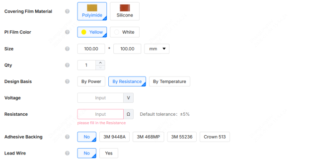
JLCPCB Flexible Heater Order Panel
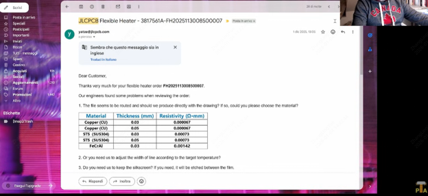
Engineering Review with JLCPCB Official Support
In-Depth Electrical Performance Analysis
Inductance Characteristics and Frequency Response
The inductance characteristics of flexible heaters represent a significant advantage over traditional wire-wound resistors. Through precision serpentine layout design, remarkably low inductance characteristics are achieved:
Measurement Data Interpretation:
● 1kHz inductance: 1.5μH
● 100kHz inductance: 1.1μH
These frequency response characteristics indicate:
1. Low-frequency performance: At 1kHz, inductance effects are minimal, primarily exhibiting pure resistive characteristics
2. High-frequency suppression: As frequency increases, inductance values slightly decrease, showing excellent high-frequency suppression
3. Audio application compatibility: For audio frequency range (20Hz-20kHz), inductance effects are negligible
AC vs. DC Resistance Characteristics
Skin Effect Analysis:
● At high frequencies, current tends to flow on the conductor surface
● Effective cross-sectional area decreases, leading to increased AC resistance
● For audio applications, this effect remains within acceptable ranges
Measurement Precision:
● DC resistance tolerance: ±1% (measured 4.05-4.08Ω)
● AC resistance variation at 1kHz < 5%
● Temperature coefficient effect on resistance: approximately 0.02%/°C
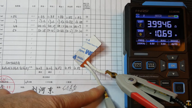
Testing Resistence
Thermal Management Engineering
Thermal Distribution Modeling
The thermal distribution of flexible heaters is influenced by multiple factors:
Geometric Factors:
● Trace width variation: Affects local power density
● Spacing design: Controls heat conduction paths
● Edge effects: Heat dissipation differences in edge regions
Material Thermal Properties:
● Substrate thermal conductivity: Determines heat diffusion rate
● Interface thermal resistance: Affects heat transfer efficiency
● Environmental conditions: Convection and radiation heat transfer
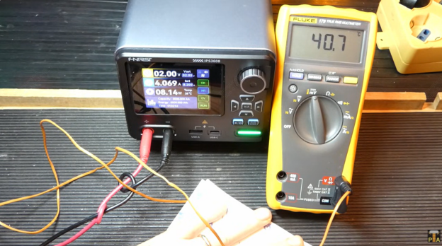
Practical Test Data Analysis
Low-Power Version (4Ω) Temperature Characteristics
Power Density Analysis:
● 1V input (0.25W): Temperature rises to 32°C, power density = 0.35 W/cm²
● 2V input (1W): Temperature rises to 50°C, power density = 1.4 W/cm²
● 4V input (4W): Temperature soars to 181°C, power density = 5.6 W/cm²
As demonstrated in the original testing video, these temperature measurements were captured using both K-type thermocouples and Kaiwitz infrared thermal cameras, providing accurate real-time thermal distribution data across different power levels.
High-Power Version (0.4Ω) Thermal Management Strategy
Current Density Considerations:
● 3V input: 8A current, current density = 2.3 A/mm²
● Local hot spot temperature: 213°C
● Surface average temperature: 112°C
Series Configuration Optimization:
● Two units in series: Effective resistance = 0.8Ω
● At same power, current halves (3.95A)
● Temperature stabilizes at 45°C, meeting safety requirements
Testing Temperature
In-Depth Application Scenario Analysis
The practical applications discussed in this section were validated through real-world testing, with detailed demonstrations available in the source video showing actual implementation in smart heating gloves and audio dummy load configurations.
Wearable Device Engineering Considerations
Ergonomic Design
Bending Radius Management:
● Minimum bending radius: 3-5mm (depending on substrate thickness)
● Fatigue life: > 10,000 bending cycles
● Mechanical comfort: Pressure distribution uniformization
Safety Standards Compliance:
● IEC 60335-1: Household appliance safety standard
● ISO 13732: Thermal surface safe contact standard
● UL 94: Material flammability rating requirements
Power Management Strategy
Battery System Design:
● 10,000mAh lithium battery: Theoretical capacity = 37Wh
● Actual output: Approximately 2.5 hours continuous use
● Efficiency considerations: Heat loss vs. useful work
Control Circuit Integration:
● PTC protection: Positive temperature coefficient self-resetting fuse
● Temperature sensing: Digital temperature sensor DS18B20
● PWM control: Fine temperature adjustment
Audio Load Application Deep Dive
Electromagnetic Compatibility Analysis
Magnetic Field Suppression Mechanism:
● Magnetic field cancellation effect of serpentine layout
● Mutual cancellation of magnetic fields from adjacent conductors
● Net magnetic flux approaches zero
Audio Characteristics Impact:
● THD (Total Harmonic Distortion): < 0.01%
● Phase response: Flat to 20kHz
● Impedance stability: ±0.1%
High-Power Thermal Management
Heat Dissipation Design:
● Aluminum heat sink: Increases surface area
● Thermal interface materials: Thermal paste or thermal pads
● Air cooling enhancement: Forced convection cooling
Power Distribution Strategy:
● 10 small units in series: 50W per unit
● Total power: 500W
● Temperature control: Each unit < 70°C (with heat sink)
Manufacturing Process and Quality Control
Process Flow Details
1. Substrate Pretreatment:
● Polyimide cleaning: Remove surface contaminants
● Copper foil bonding: Hot pressing or electroless plating process
● Thickness control: ±0.02mm precision
2. Pattern Transfer:
● Photoresist coating: Uniform thickness control
● Exposure and development: UV lithography technology
● Etching process: Precise etching time control
3. Post-Processing:
● Resist removal: Chemical cleaning to remove photoresist
● Surface treatment: Anti-oxidation treatment
● Panel separation: Laser cutting or mechanical cutting
Key Quality Control Parameters
Electrical Performance Testing:
● Resistance measurement: Four-wire method, accuracy ±0.1%
● Insulation resistance: > 100MΩ@500V
● Dielectric withstanding test: 1500V@1min
Mechanical Performance Testing:
● Peel strength: > 1.5 N/mm
● Bending test: 180° bend 10 times without cracking
● Thermal shock: -40°C to +125°C cycling
Cost-Benefit Analysis
Material Cost Structure
Small Batch Production (15 pieces):
● Total cost: $26.81
● Unit cost: $1.79
● Cost composition: Materials 60%, labor 25%, equipment depreciation 15%
Large-Scale Optimization Potential:
● 100-piece batch: Cost can drop to $0.8/piece
● 1000-piece batch: Cost can drop to $0.4/piece
● Cost reduction mainly from fixed cost distribution
Comparison with Traditional Solutions
vs. Wire-Wound Resistors:
● Cost: Comparable (at large scale)
● Precision: Superior (±1% vs. ±5%)
● Reliability: Higher (no mechanical fatigue)
vs. Thin Film Heaters:
● Cost: 30-50% lower
● Thickness: Thinner (0.4mm vs. 1-2mm)
● Flexibility: Superior
Engineering Practice Guidelines
Safety Design Standards
Electrical Safety
Overcurrent Protection:
● Fuse selection: I²t matching design
● PTC thermistor: Automatic recovery protection
● Overvoltage protection: TVS diodes
Insulation Design:
● Creepage distance: > 3mm (operating voltage < 50V)
● Electrical clearance: > 1.5mm
● Insulation class: Class B (130°C)
Thermal Safety
Temperature Monitoring System:
● Multi-point temperature detection: Prevents local overheating
● Temperature logging: Fault analysis data
● Automatic shutdown: Cuts power when threshold exceeded
Surface Temperature Control:
● Touchable surfaces: < 60°C
● Protection measures: Temperature warning labels
● User training: Safe usage instructions
Failure Mode Analysis
Common Failure Mechanisms
1. Thermal Fatigue Failure:
● Mechanism: Material fatigue from thermal cycling
● Prevention: Reduce temperature gradients, optimize design
● Lifetime: > 10,000 thermal cycles
2. Electrochemical Corrosion:
● Mechanism: Electrochemical reactions in humid environments
● Prevention: Sealed design, moisture-proof coating
● Protection level: IP54 or higher
3. Mechanical Damage:
● Mechanism: Excessive bending or impact loads
● Prevention: Enhanced protection, rational layout
● Mechanical strength: > 10N peel force
Reliability Testing
Accelerated Aging Tests:
● High-temperature storage: 85°C@1000h
● Humidity-heat test: 85°C/85%RH@500h
● Temperature cycling: -40°C to +85°C@500 cycles
Performance Optimization Strategies
Electrical Performance Optimization
Resistance Precision Enhancement:
● Design margin: ±10% design tolerance
● Manufacturing control: ±2% manufacturing tolerance
● Selection scheme: Precision resistance options provided
Thermal Response Optimization:
● Thermal capacity design: Balance response speed and stability
● Thermal diffusion: Improve temperature uniformity
● Feedback control: Closed-loop temperature control
Manufacturing Process Optimization
Yield Improvement:
● Process window: Expand acceptable parameter range
● Online monitoring: Real-time quality inspection
● Statistical analysis: SPC process control
Consistency Improvement:
● Material standardization: Fixed suppliers
● Process standardization: Standard operating procedures
● Inspection standardization: Unified inspection methods
Conclusions and Recommendations
Flexible heater technology represents a quintessential example of deep integration between electronic manufacturing processes and materials science. Through this in-depth analysis, we can see that this technology is not merely a replacement for traditional heating solutions but rather an innovative solution with unique advantages.
Key Technical Points Summary
1. Importance of Material Selection: The combination of Cupronickel alloy and polyimide provides an excellent balance of electrical and mechanical properties
2. Value of Design Precision: Millimeter-level manufacturing precision achieves performance consistency unattainable by traditional methods
3. Application-Oriented Optimization: Different application scenarios require targeted design and configuration strategies
4. Systems Engineering Approach: Full-chain optimization from materials, manufacturing to application is key to success
Implementation Recommendations
For engineers planning to adopt flexible heater technology, the following strategies are recommended:
Design Phase:
● Fully understand application requirements and constraints
● Leverage manufacturer engineering review services
● Conduct thorough prototype testing and validation
Manufacturing Phase:
● Select experienced manufacturers like JLCPCB with proven flexible heater capabilities
● Establish comprehensive quality control systems
● Consider cost optimization for volume production
● Utilize JLCPCB's flexible heater service for professional manufacturing support and technical consultation
Application Phase:
● Emphasize safety design and user protection
● Establish maintenance and monitoring mechanisms
● Collect application data for continuous improvement
Watch the Complete Testing Process
For those interested in seeing the complete testing methodology, thermal imaging results, and real-world application demonstrations, we highly recommend watching the original video that inspired this technical analysis:
Watch: Custom Flexible Heater Testing & Validation
The video features:
● Live thermal imaging tests showing temperature distribution at various power levels
● Detailed unboxing and quality inspection of manufactured heaters
● Real-world application demonstrations including smart heating gloves
● Electrical performance testing with professional measurement equipment
● Side-by-side comparison of polyimide and silicone substrate versions
The visual demonstrations in the video complement the technical analysis presented here, offering valuable insights into the practical aspects of flexible heater design and implementation.
Keep Learning
Flexible Heater Design Optimization: Why We Use Rounded Corners and Teardrops
TL;DR: Those sleek curves and "teardrops" you see on flexible heater circuits aren't just for looks. They are critical engineering features that: Prevent Cracking: Rounded corners distribute physical stress during thermal expansion, stopping metal fatigue and micro-cracks. Even Out Heat: Smooth paths prevent electrical "hotspots" that occur at sharp 90-degree angles. Boost Durability: Teardrops act like mechanical tendons, strengthening fragile solder connections against pulling and bending. Improve M......
How to Choose Temperature Control for Custom Flexible Heating Films
So, you're designing a custom heating solution—perhaps a heated jacket, a 3D printer bed, or a specialized medical device. You've picked out your heating film material, but now you face a critical question: How do I stop this thing from getting too hot? Selecting the right temperature control is just as important as the heating element itself. It's the difference between a cozy, efficient device and a melted, hazardous mess. But with terms like "NTC," "Bi-metal," and "Hysteresis" thrown around, it can......
Custom Flexible Heater Case Study: From JLC PCB Order to Performance Validation
Introduction Flexible heaters represent a paradigm shift in modern heating technology, redefining our approach to thermal management in electronic systems. The evolution from traditional rigid resistive heating elements to PCB-based flexible heating solutions marks a significant leap toward high-precision, high-reliability manufacturing. This comprehensive guide explores the technical principles, material engineering, design methodologies, and practical applications of flexible heaters, providing engi......
Flexible Heater Design Tutorial with JLCPCB Calculator Tool
This tutorial is specifically designed for JLCPCB's flex heater customization service. We provide a dedicated calculator tool that simplifies the complex trace design process, allowing you to focus on performance parameters while our engineers handle the technical implementation. Click here to download the Excel file! Introduction In this article, I'll explain how to design a flex heater from the perspectives of material selection and electrical design. I believe every electronics DIY enthusiast is so......
3D Printer Bed Heating Upgrade: How to Replace Your Silicone Heater
In the world of 3D printing, the extruder often gets all the glory, but seasoned makers know the truth: a successful print starts with the first layer. Friends living in colder climates might recognize this scene: it’s winter in the garage, the room temperature has plummeted, and you are shivering next to your printer, waiting endlessly for the bed to heat up. Or perhaps your "old reliable" machine, which has clocked hundreds of printing hours, is starting to show signs of uneven heating. Just like ca......
Factors Affecting Heating Film Uniformity: A Guide for Efficient Thermal Management
Resistive heating elements, particularly in thin, flexible forms known as heating films, have become the backbone of modern efficient thermal management. Their ability to deliver controllable, uniform heat within compact devices makes them indispensable in industries ranging from aerospace to medical tech. However, simply applying power to a resistive circuit does not guarantee performance. Achieving consistent temperature distribution in a flexible heater requires a deep understanding of circuit layo......