Rigid PCB vs. Flexible PCB: Making the Right Choice
12 min
- Understanding Flex PCBs and Rigid PCBs:
- Factors to Consider in PCB Selection:
- Application Examples and Use Cases:
- FAQ about Rigid PCB and Flexible PCB
- Conclusion:
Key Takeaways
Rigid PCB vs Flexible PCB: Making the Right Choice lies in understanding their fundamental differences — Rigid PCBs offer superior mechanical stability, cost-effectiveness, and multi-layer capability (up to 20+ layers at JLCPCB), making them ideal for traditional electronics, while Flexible PCBs excel in space-constrained, dynamic, and 3D applications with their polyimide-based bendability (1-4 layers) and critical design rules like minimum bending radius and stiffener placement. By carefully evaluating application needs, space, cost, and reliability factors, designers can select the optimal PCB type to achieve the best performance, manufacturability, and overall project success.
In today's world of modern technology, Printed Circuit Boards (PCBs) serve as the foundation of nearly all electronic devices. The two most prevalent types are Rigid PCBs and Flexible PCBs (Flex PCBs or FPCs). Choosing the right type requires a clear understanding of their unique characteristics, design considerations, manufacturing capabilities, and real-world applications. This article explores these aspects in detail, with reference to JLCPCB's current manufacturing capabilities.
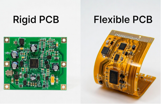
Understanding Flex PCBs and Rigid PCBs:
Rigid PCBs, as the name suggests, are inflexible circuit boards made from solid substrates such as fiberglass-reinforced epoxy. They possess a rigid structure and provide excellent mechanical support for components. Unbending PCBs are generally utilized in applications where dependability and sturdiness are significant, for example, PC motherboards, modern hardware, and auto gadgets. The inflexibility of these sheets considers simple mounting of parts, giving a steady stage to fastening and interconnecting electronic parts.
Flexible PCBs (Flex PCBs), on the other hand, are manufactured using flexible polymer materials like Polyimide (PI) or Polyester (PET). JLCPCB supports 1–4 layer Flex PCBs with dielectric thicknesses of 25 μm (ultra-thin) or 50 μm, including adhesive-free options and transparent PET (up to 85% transmittance). This flexibility allows the board to bend, fold, and fit into tight or irregular spaces, making them ideal for dynamic or space-constrained applications such as wearables, aerospace, and medical devices.
Factors to Consider in PCB Selection:
- Choosing between Rigid PCBs and Flexible PCBs is a critical decision that directly impacts the performance, reliability, cost, and manufacturability of your final product. Several key factors must be carefully evaluated:
- Application Requirements: The operating environment plays a decisive role. Rigid PCBs are preferred when high mechanical strength, structural stability, and resistance to shock are needed. Flexible PCBs are ideal for applications that require repeated bending, folding, or installation in curved surfaces. For example, devices exposed to vibration (such as automotive or industrial equipment) may favor rigid boards, while dynamic movement applications benefit greatly from flex circuits.
- Space Constraints: In modern compact electronics, space is often the biggest limitation. Flexible PCBs offer significant advantages here because they can be bent, folded, or wrapped around components, allowing three-dimensional assembly. This can dramatically reduce the overall product volume. Rigid PCBs, by contrast, are better suited for flat, spacious layouts where traditional mounting is possible.
- Cost Considerations: Rigid PCBs generally have lower manufacturing costs due to simpler production processes and widely available materials like FR-4. Flexible PCBs use more expensive polyimide materials and require specialized handling, which increases cost — especially in small to medium production volumes. However, in high-volume production or when space savings lead to smaller enclosures, the total system cost of using Flex PCBs may actually be lower. JLCPCB customers should compare quotes for both options based on layer count and quantity.
- Reliability: Both types can achieve high reliability when designed correctly. However, Flex PCBs must be evaluated for bending cycle life, while Rigid PCBs need to consider thermal expansion, vibration resistance, and long-term durability in harsh environments. Factors such as temperature range (-40°C to 125°C for standard materials), humidity, and chemical exposure should all be reviewed according to the product’s intended use.
- Assembly and Testing: Rigid PCBs are easier for automated assembly and testing. Flexible PCBs may require special fixtures, manual handling in some cases, and more careful inspection of bend areas.
Design Considerations for Flex PCBs:
Unlike rigid boards, Flexible PCBs require special design rules due to their dynamic mechanical properties. Proper design is essential to prevent trace breakage, delamination, or solder joint failure during bending or long-term use.
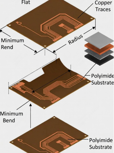
- Bending Radius:This is one of the most critical parameters. Exceeding the minimum bending radius can cause immediate or fatigue damage to copper traces and the substrate. JLCPCB recommends the following guidelines for static bending:
| Layers | Minimum Bend Radius (Static) | Recommendation for Dynamic Use |
|---|---|---|
| Single Layer | Thickness × 6 | Thickness × 10 or more |
| Double Layer | Thickness × 12 | Thickness × 20 or more |
| Multi Layer | Thickness × 24 | Avoid dynamic bending if possible |
For a typical JLCPCB 2-layer Flex PCB (total thickness ≈ 0.11 mm), the minimum static bend radius is approximately 1.32 mm. Dynamic applications (repeated bending, such as in foldable devices) require much larger radii and preferably adhesive-less polyimide material.
- Component Placement: Components should be placed only in reinforced (stiffened) areas whenever possible. Heavy components, BGAs, or connectors must not be located directly in the bending zone. JLCPCB supports selective stiffeners using FR-4, additional polyimide layers, or stainless steel sheets to provide stable mounting areas while preserving flexibility elsewhere.
- Flex-to-Rigid Transitions: Many designs combine flexible and rigid sections (Rigid-Flex). In these transition zones, stress concentration is common. Best practices include using gradual thickness tapering, filleted corners, teardrop vias, and additional coverlay reinforcement. JLCPCB can produce boards with stiffeners bonded in specific areas to ease this transition.
- Trace Routing and Layout: Traces should run perpendicular to the bending direction when possible. Use rounded traces instead of sharp 90° angles in flexing areas. Wider traces and hatched ground planes can improve both flexibility and reliability. Avoid placing vias in high-flex zones.
- Material Selection: JLCPCB offers Polyimide (PI) as the primary flexible material, which provides excellent thermal stability (up to 200°C+). For cost-sensitive transparent applications, Polyester (PET) is also available. Adhesive-less constructions are recommended for high-reliability or high-cycle bending applications.
The impact of these design considerations on the overall functionality of the flex PCB cannot be overstated. Failure to address these factors adequately may result in performance issues, reliability problems, or even premature failure of the PCB.
Design Considerations for Rigid PCBs:
Rigid PCBs are the most commonly used type of circuit board due to their excellent mechanical stability, ease of assembly, and cost-effectiveness. However, proper design is still essential to ensure signal integrity, thermal performance, manufacturability, and long-term reliability.
- Board Size: Rigid PCBs come in different sizes, and the picked size ought to line up with the accessible space in the application. It is essential to consider the dimensions of the electronic components, the enclosure, and any other design constraints to ensure the PCB fits properly.
- Mounting Options: Rigid PCBs offer different mounting options, such as surface mount technology (SMT) or through-hole technology (THT). The choice of mounting option depends on factors such as component type, assembly process, and desired mechanical strength. You must carefully consider the mounting method to ensure compatibility with the chosen components and the overall mechanical stability of the PCB assembly.
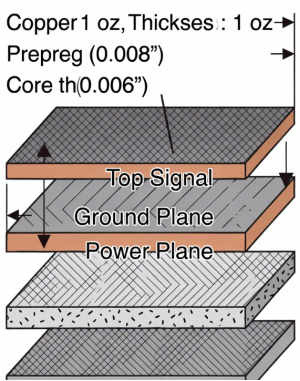
- Layer Stackup: Rigid PCBs can have multiple layers, allowing for complex circuit designs. The layer stackup plays a crucial role in achieving signal integrity, power distribution, and thermal management. You must carefully consider the number of layers, their arrangement, and the use of ground and power planes to optimize the performance and reliability of the PCB.stack up
- Thermal Management: Rigid PCBs, especially those with high-power components, must consider heat dissipation. Techniques include using thicker copper (2 oz or 3 oz), thermal vias, copper pours, and sometimes metal core (MCPCB) options. JLCPCB provides standard FR-4 as well as high-TG FR-4 materials for better thermal performance.
- Design for Manufacturability (DFM): To achieve the best yield and lowest cost at JLCPCB, designers should follow minimum trace width/spacing (3.5 mil / 3.5 mil for standard process), proper via sizing, sufficient annular rings, and keep-out zones for tooling holes. Panelization is recommended for high-volume production to reduce assembly costs.
The effect of these plan contemplations on the general usefulness and manufacturability of the inflexible PCB ought not be ignored. Each decision made during the design process can have a significant impact on the performance, reliability, and cost of the final product.
Application Examples and Use Cases:
To further understand the practical applications of flex PCBs and rigid PCBs, let's consider some examples where each type is the preferred choice.
Flex PCBs:
a. Wearable Technology: Flex PCBs are broadly utilized in wearable gadgets because of their capacity to adjust to the state of the human body. They enable the integration of electronics into clothing, fitness trackers, smartwatches, and medical monitoring devices.
b. Aerospace: The aerospace business vigorously depends on flex PCBs for their lightweight and space-saving qualities. They are used in applications such as satellites, aircraft avionics, and communication systems.
c. Medical Devices: Flex PCBs find extensive use in medical devices, including implantable devices, medical imaging systems, and diagnostic equipment. Their flexibility allows for compact designs and ease of integration into medical instruments.
Rigid-PCBs:
a. Consumer Electronics: Consumer electronics like smartphones, tablets, televisions, and gaming consoles frequently contain rigid PCBs. Their steady design and simplicity of part mounting make them reasonable for high-volume creation and financially savvy producing.
b. Automotive Electronics: Rigid PCBs are broadly utilized in car applications because of their sturdiness and protection from vibration and cruel conditions. They are found in engine control units, infotainment systems, and safety modules.
c. Industrial Equipment: Rigid PCBs are preferred in industrial equipment due to their ability to withstand harsh operating conditions. They are used in control systems, motor drives, and power distribution units.
Comparison and Decision-Making:
Now that we have explored the characteristics, design considerations, and application examples of both flex PCBs and rigid PCBs, let's compare their key attributes to aid in the decision-making process:
Flexibility: Flex PCBs offer flexibility and the ability to conform to irregular shapes, while rigid PCBs maintain a stable structure and provide excellent mechanical support.
Space Efficiency: Flex PCBs excel in applications with space constraints, allowing efficient utilization of available space. Rigid PCBs are suitable for applications with ample space availability.
Manufacturing Cost: Rigid PCBs generally have lower manufacturing costs due to their simpler construction. Flex PCBs may involve additional manufacturing steps and materials, making them comparatively more expensive.
Reliability: Both flex PCBs and rigid PCBs can be reliable when designed and manufactured correctly. However, factors such as operating conditions, environmental stresses, and design complexity can impact the reliability of each type.
| Attribute | Rigid PCBs | Flexible PCBs (JLCPCB) |
|---|---|---|
| Flexibility | None (high stability) | Excellent (bendable) |
| Space Efficiency | Suitable for flat layouts | Superior for compact/3D designs |
| Weight | Heavier | Much lighter |
| Manufacturing Cost | Lower | Higher (special materials & processes) |
| Vibration Resistance | Good | Excellent |
| Max Layers (JLCPCB) | Up to 20+ | 1–4 layers |
| Best Applications | Consumer electronics, Automotive, Industrial | Wearables, Medical, Aerospace |
It is crucial to evaluate these factors alongside the specific requirements of the project to make an informed decision. Consider the application needs, available space, cost constraints, and reliability requirements to select the most suitable PCB type.
FAQ about Rigid PCB and Flexible PCB
Q: What is the main difference between Rigid PCB and Flexible PCB?
Rigid PCBs are made from solid FR-4 material and provide excellent mechanical stability and support, making them ideal for traditional flat designs. Flexible PCBs use Polyimide (PI) or PET substrates, allowing them to bend, fold, and fit into tight or irregular spaces. JLCPCB supports up to 20+ layers for Rigid PCBs and 1–4 layers for Flexible PCBs.
Q: When should I choose Flexible PCB instead of Rigid PCB?
Choose Flexible PCBs when your design has space constraints, requires 3D assembly, needs to withstand vibration, or involves repeated bending (such as in wearables, medical devices, or aerospace applications). Rigid PCBs are better for cost-sensitive, high-volume, or mechanically stable applications like consumer electronics and automotive systems.
Q: What is the recommended minimum bending radius for Flexible PCBs?
According to JLCPCB guidelines, the minimum static bending radius is generally: Single Layer = thickness × 6, Double Layer = thickness × 12, Multi Layer = thickness × 24. For a typical 0.11 mm 2-layer Flex PCB, the minimum static bend radius is about 1.32 mm. Dynamic (repeated) bending requires larger radii.
Q: How many layers can JLCPCB manufacture for Rigid and Flexible PCBs?
JLCPCB supports up to 20+ layers for Rigid PCBs, while Flexible PCBs are limited to 1–4 layers. Proper layer stackup design is especially important for multi-layer Rigid PCBs to ensure signal integrity and thermal performance.
Q: Which type of PCB is more expensive — Rigid or Flexible?
Rigid PCBs generally have lower manufacturing costs due to simpler materials and processes. Flexible PCBs are more expensive because they use specialized polyimide materials and require additional handling. However, Flex PCBs can reduce overall system cost by saving space and simplifying assembly in compact products.
Q: What are the most important design considerations when using Flexible PCBs?
Key considerations include following the minimum bending radius, placing components only in stiffened areas, designing smooth Flex-to-Rigid transitions, routing traces perpendicular to the bend direction, and using stiffeners where needed. Always review JLCPCB’s design guidelines before production.
Conclusion:
In the domain of PCBs, the decision between flex PCBs and unbending PCBs relies upon different variables. Understanding the characteristics, design considerations, and application examples associated with each type is crucial to make the right decision. Flex PCBs offer flexibility and compactness, making them suitable for applications with irregular shapes and space constraints. Rigid PCBs provide stability, durability, and cost advantages, making them suitable for applications with ample space availability and high-volume production.
By carefully considering the project requirements and evaluating the key factors, you can select the appropriate PCB type to achieve optimal performance, reliability, and cost-efficiency in their electronic designs.
Popular Articles
• Choosing the Right Bend Radius for Durable Flexible PCBs
• Flexible Meets Durable: Understanding Rigid-Flex PCB Technology
• PCB Stiffeners: An Essential Requirement for Flexible Circuits
• The Ultimate Guide to Flexible PCB: Types, Design, and Applications
• 45 Must-Know Flex PCB Design Tips You Can't Afford to Miss!
Keep Learning
Choosing the Right Bend Radius for Durable Flexible PCBs
Key Takeaways Mastering the bend radius is essential for reliable flexible PCB design. Following IPC-2223 guidelines, maintain a minimum of 6× total thickness for static bends and 100× for dynamic applications, while using thinner RA copper, adhesiveless polyimide, staggered traces, and cross-hatched patterns in flex zones. Proper material selection, layer stackup optimization, and adequate clearance from stiffeners can dramatically extend flex life and prevent premature trace cracking or delamination......
Flex PCB Stackup Design Guide: Layers, Materials & Reliability
Key Takeaways A reliable flex PCB starts with the right stackup design. The layer structure, material selection, and copper arrangement directly affect flexibility, bend life, electrical performance, and manufacturing reliability. This guide explains single-sided, double-sided, and multilayer flex PCB stackups, including polyimide materials, coverlay, copper types, and key design considerations for creating durable flexible circuits with JLCPCB. Did you ever wonder how a foldable phone can last for 20......
Flexible Meets Durable: Understanding Rigid-Flex PCB Technology
In the rapidly evolving world of electronics, the demand for smaller, more reliable, and more versatile devices continues to grow. To meet these demands, engineers and designers are increasingly turning to Rigid-Flex PCBs. The circuit boards combine rigid and flexible substrates into a single interconnected structure. This combination allows for complex designs that can bend and flex in specific areas while maintaining rigidity in others. To manufacture rigid flex PCBs, IPC offers advice and best prac......
PCB Stiffeners: An Essential Requirement for Flexible Circuits
A printed circuit board stiffener plays an important role when it comes to offering mechanical support to a PCB. They are particularly helpful for flexible circuit boards, that given their name, are flexible and in need of stiffness in certain places. Stiffeners are particularly required when components are placed in a flex zone & the weight of these components stresses the flex material. These components provide a rigid connection from the flexible portion to the solid board. This solidity makes appl......
The Ultimate Guide to Flexible PCB: Types, Design, and Applications
Key Takeaways JLCPCB 1–4 Layer Flex PCB: Supports 1 to 4-layer FPCs with polyimide (PI) substrates and trace/space down to 3/3 mil. Stiffener Selection: Use PI (0.1–0.25mm) for ZIF connectors, FR4 (0.1–1.6mm) for SMT support, and Stainless Steel (0.1–0.3mm) for high rigidity. Layout Optimization: Use cross-hatched copper ground planes and stagger 2-layer traces to eliminate the "I-Beam effect." Surface & Protection: Combine Immersion Gold (ENIG 1u"/2u") for SMT planarity with flex coverlay to protect ......
Medical Flex Circuits: Manufacturing, Applications, Materials, and Design Guide
Medical flex circuits made to fit inside a 1.0 mm disposable endoscope, wrap around a hearing aid shell, and sit on a patient's arm for ten straight days. When one fails, it is not a warranty return but a device history file and a regulatory conversation. In this guide, you will learn: What separates a medical flex circuit from a consumer one How they are built, tested, and released Polyimide, copper, coverlay, and stiffener choices Fine line, bend radius, and layer count limits What to check before c......