Help Center
JLCPCB FPC Impedance Trace Width and Spacing Design Guide
Last updated on Jun 26, 2026
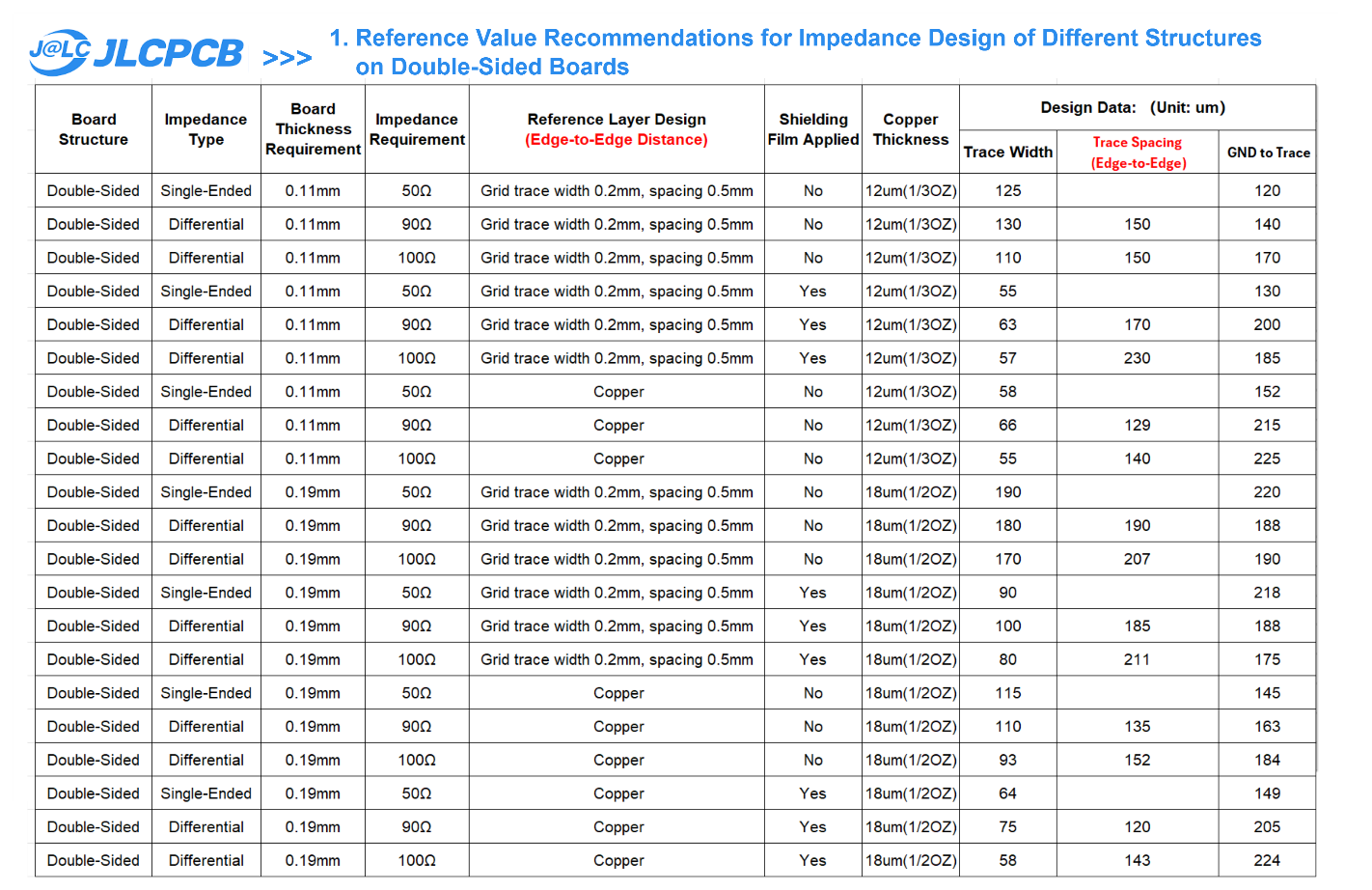
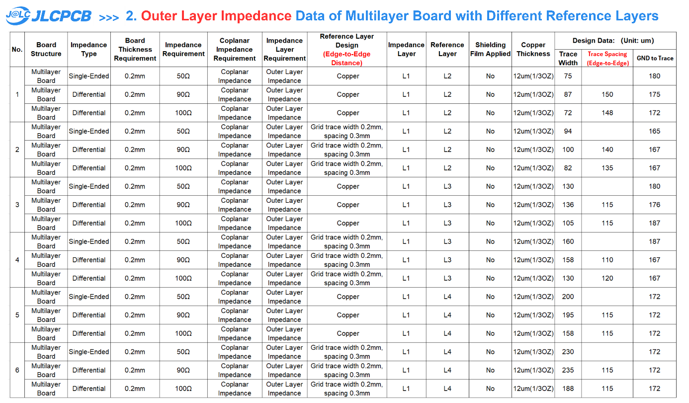
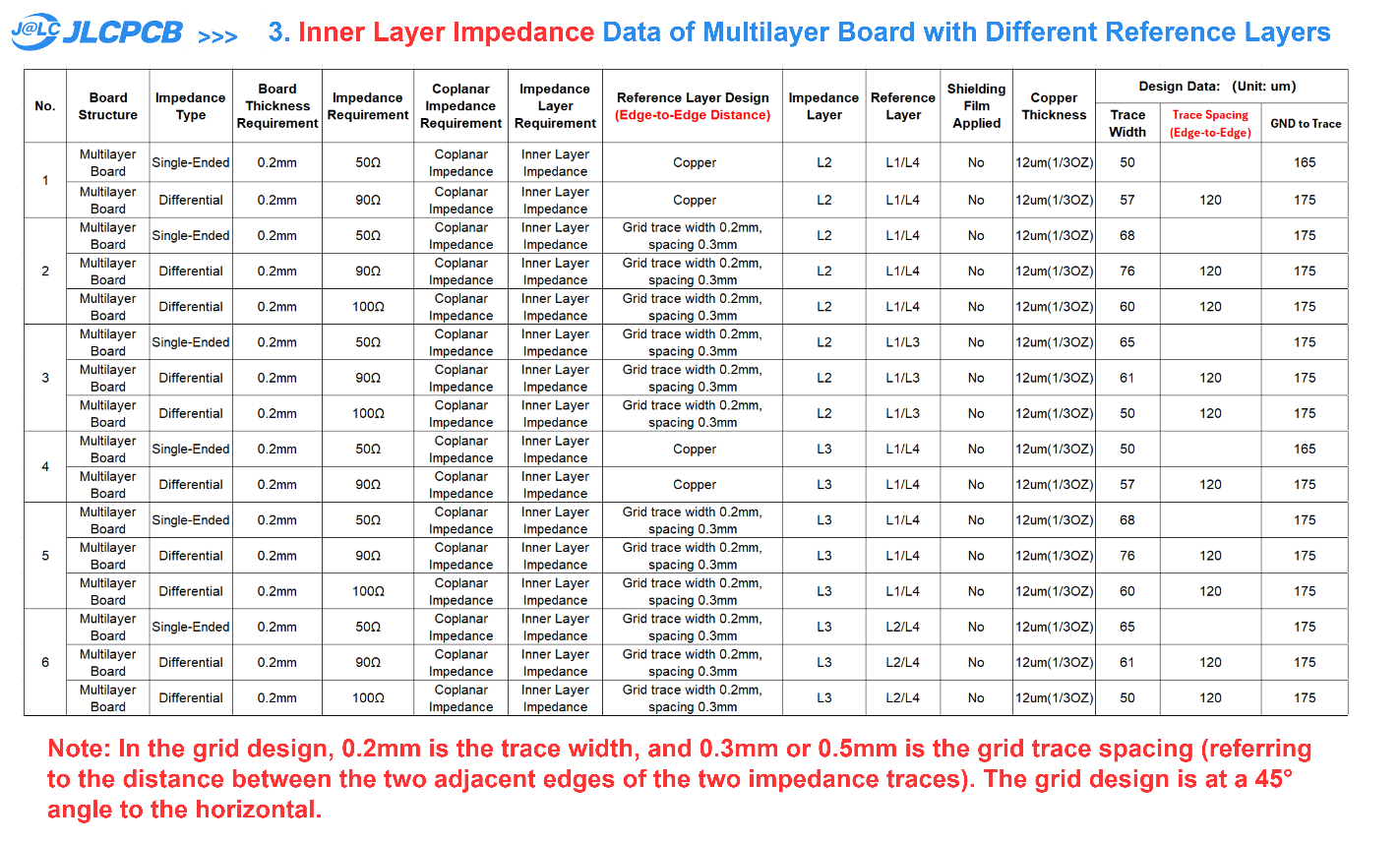
Accurately calculating FPC impedance using simulation software can be challenging. Therefore, it is recommended to base your designs on the empirical trace widths derived from JLCPCB's practical experience. Since JLCPCB does not currently offer impedance testing services for FPCs, we advise producing a prototype for initial verification.
Please note: Placing an order directly using the trace widths provided below will result in an impedance tolerance of approximately ±20%. If you have strict tolerance requirements, please contact JLCPCB's technical staff.