
Recommendations for BOM / CPL File Preparation
Last updated on Jan 19, 2026
I. Use Official Standard File Formats
We strongly recommend preparing your files using the official standard templates and format guidelines provided on our website. This is the most effective way to ensure high system recognition accuracy during automated processing.
Please modify the column headers in your files to match the standard field names recognized by our system, so that all information can be read and processed correctly.
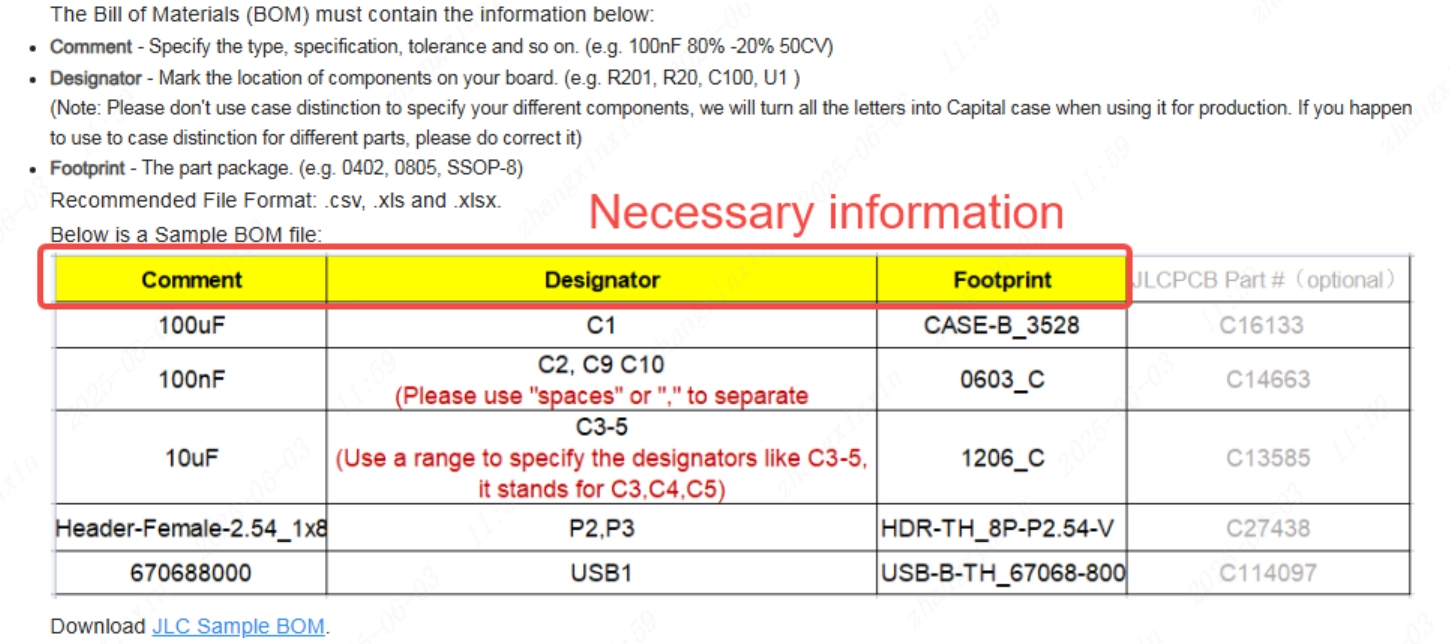
- BOM File Format Guide: Bill of Materials for PCB Assembly
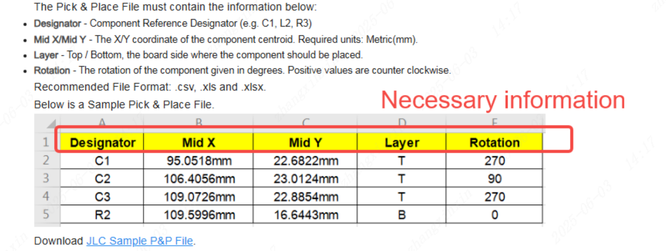
- CPL File Format Guide: Pick & Place File for PCB Assembly
II. Ensure Complete and Consistent Reference Designators Between BOM and CPL Files
1. Exact Matching of Reference Designators
Please verify that all reference designators (e.g., R1, C2, U3) listed in the BOM file exactly match those listed in the CPL file.
Any mismatch may result in missing placement or incorrect component mounting.
Only components whose reference designators appear in both the BOM and the CPL files can be correctly recognized by the system for assembly.
2. Case Sensitivity Consistency
The letter case of reference designators must be consistent between the BOM and CPL files (e.g., “R1” ≠ “r1”).
Inconsistent capitalization may cause components to be categorized as “Unselected Parts.”
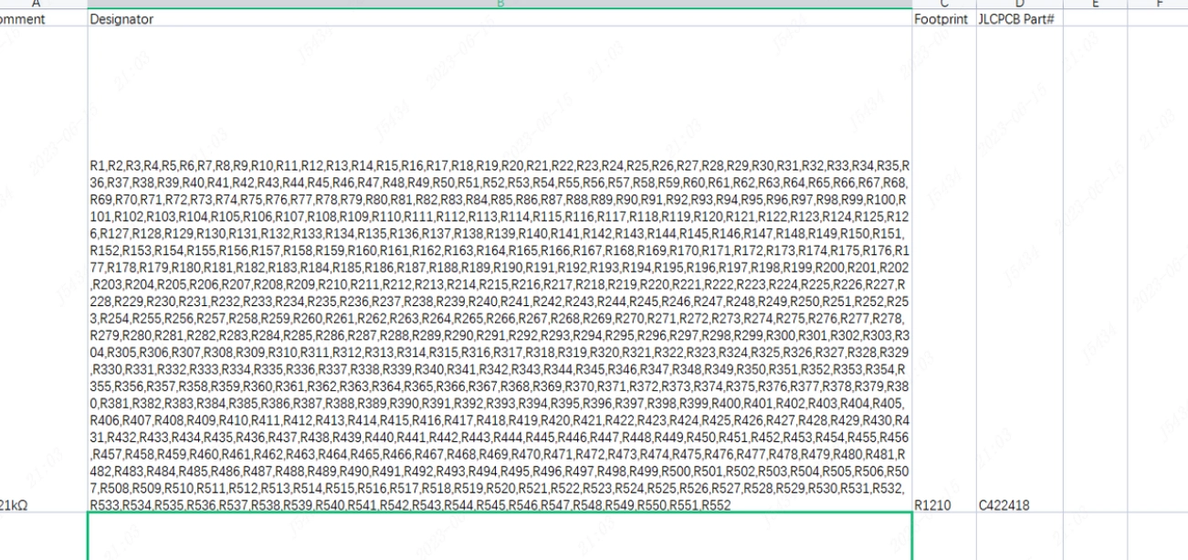
III. Limit the Number of Reference Designators per BOM Line
Each BOM line should contain no more than 200 reference designators.
If a single material corresponds to more than 200 reference designators, please split them into multiple rows, ensuring that each row contains 200 or fewer reference designators, to avoid system parsing errors or omissions.
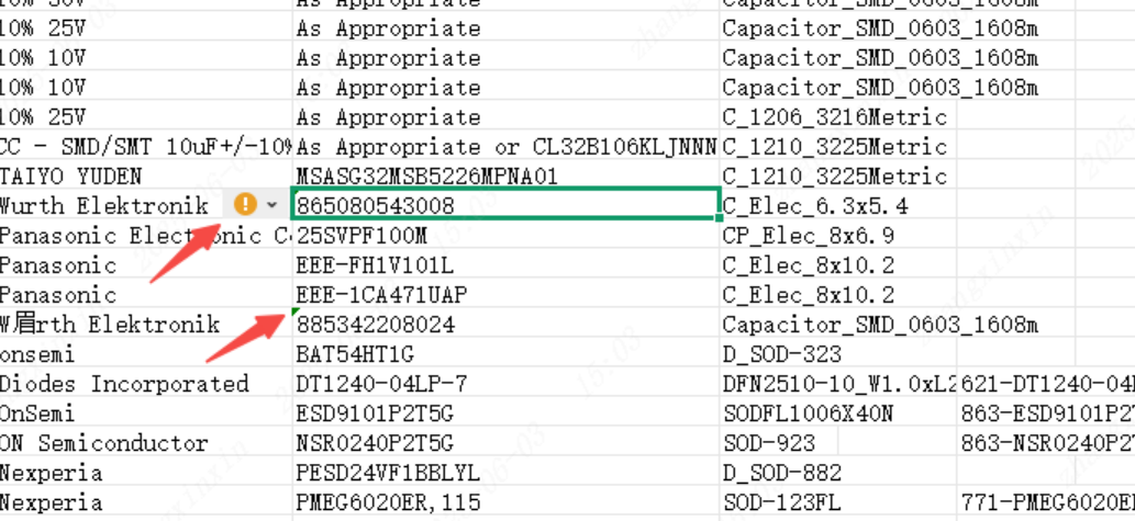
IV. Remove Formatting Anomalies in the Files
1. Please remove the green triangle error indicators (Excel error-check warnings) in the upper-left corner of cells.
2. If formatting issues persist, we recommend copying and pasting the data into a new Excel worksheet to ensure clean and standardized data.
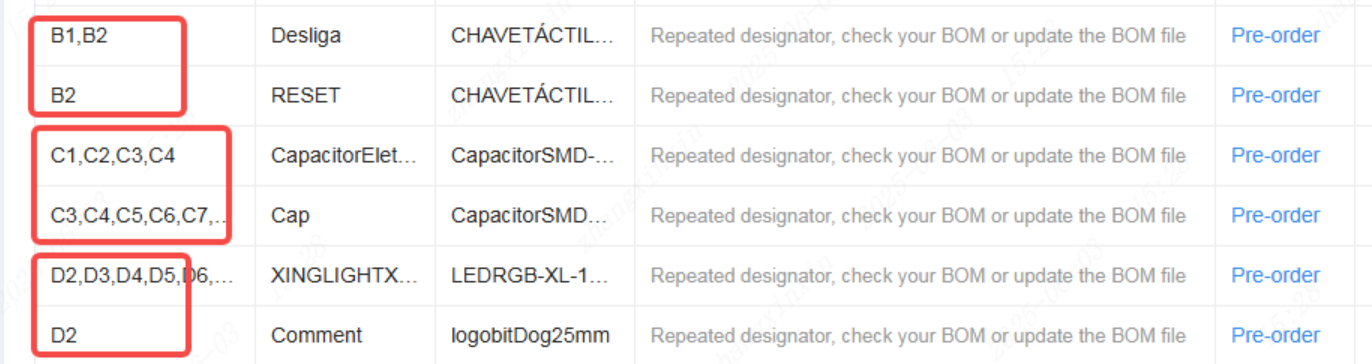
V. Check for Duplicate Reference Designators in the BOM
Ensure that each reference designator appears only once in the entire BOM file.
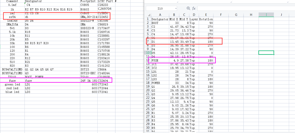
VI. Ensure BOM Information Matches Actual Component Specifications
Our component procurement process is strictly based on the BOM. Therefore, all BOM information must be accurate and consistent with the actual component specifications.
1. After uploading the BOM, you may hover your mouse over the JLCPCB Parts Number to view detailed component information and verify that it matches your entered data.
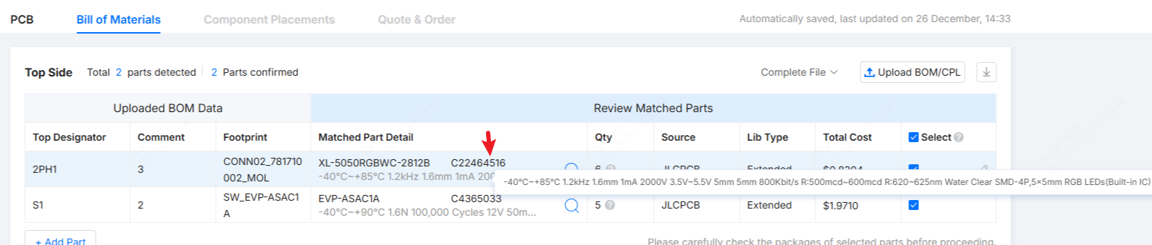
2. If multiple different values or specifications exist under the same BOM designation, please carefully verify the details, remove incorrect entries, and update the BOM promptly to prevent duplicate purchases or incorrect component sourcing.
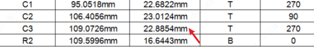
VII. Verify Coordinate Units and Spacing in the CPL File
1. Ensure that all coordinate values use a consistent unit (e.g., all in millimeters, mm).
2. Ensure that the minimum distance between any two different reference designators is not less than 0.2 mm.
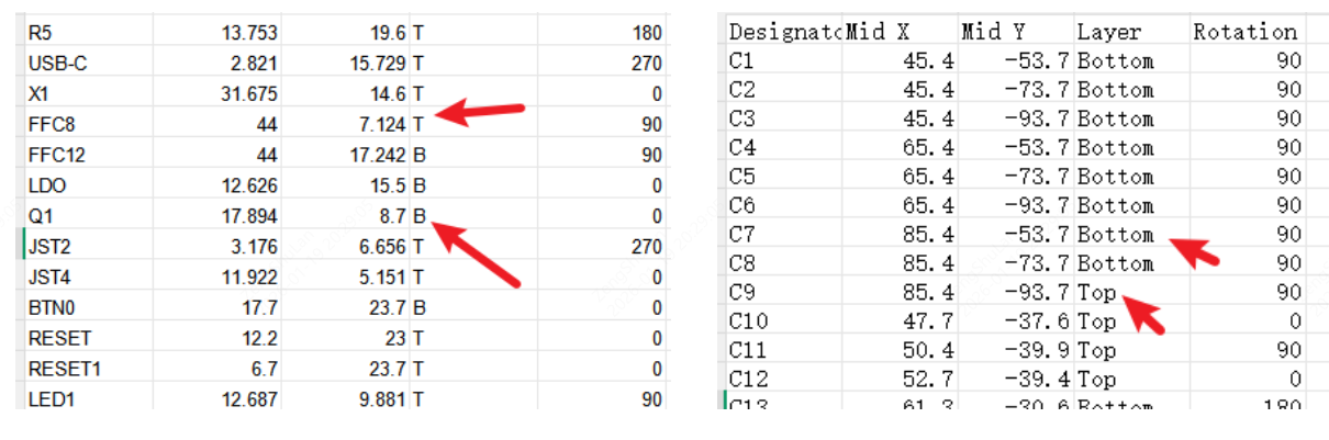
VIII. Include Top and Bottom Layer Data in the Same CPL File
Please include both top-layer and bottom-layer placement data in a single CPL file.
Use “T” and “B” (or “Top” and “Bottom”) to distinguish the placement layers, so the factory can clearly identify the SMT side.
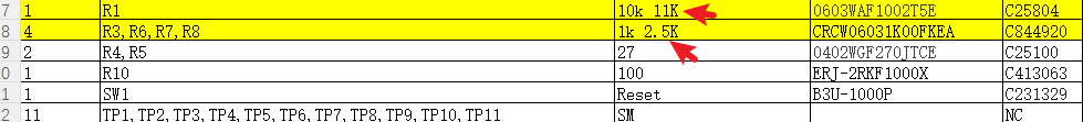
IX. Electronic Component Naming Conventions
Use correct and standardized reference designator prefixes:
- “C” for capacitors
- “R” for resistors
Incorrectly naming a resistor with the prefix “C” may cause material identification confusion.
We strongly recommend strictly following industry naming conventions—capacitors starting with “C” and resistors starting with “R”—to ensure accurate component classification and identification.