
How to Export BOM and CPL Files from EAGLE [Step-by-Step Guide]
Last updated on Jun 18, 2026
To place an SMT Assembly order on JLCPCB, you need two files.
The first is the BOM (Bill of Materials), which lists the part number and its cost, and the second is the CPL file, also known as the Centroid or Pick & Place file. This file tells the machine where and in which orientation to place each part.
This guide shows the fastest way to produce both from EAGLE using JLCPCB's official exporter, then upload them for your order.
Version Details
This guide was verified on EAGLE 9.6.2. The steps are the same for nearby EAGLE/Fusion versions; only some toolbar icons differ slightly.
Why use the JLCPCB SMTA Exporter ULP?
EAGLE's built-in BOM and Pick & Place exports use EAGLE's own column names and unit format. So the files need manual formatting before uploading for the JLCPCB assembly order. JLCPCB instead provides a free ULP (User Language Program) called jlcpcb_smta_exporter.ulp that does the work for you:
- Exports the BOM and CPL together in exactly the format JLCPCB expects.
- Writes the correct headers and millimetre coordinates automatically.
- Handles component rotations so parts are placed the right way round.
- Read your LCSC_PART attribute straight into the BOM's part-number column.
In short, it is the one-click solution in EAGLE that gives you upload-ready files, with no spreadsheet editing.
The two files JLCPCB needs
The BOM (Bill of Materials)
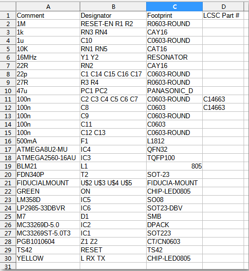
For JLCPCB the BOM is a .csv/.xls/.xlsx file with the columns as given by the reference BOM. Comment, Designator, Footprint and the JLCPCB / LCSC Part #. Here is JLCPCB's official sample BOM to match:
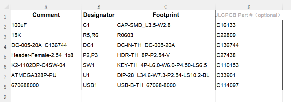
JLCPCB's sample BOM
The CPL file (Centroid / Pick & Place)
Centroid, CPL and Pick & Place are three names for the same file. It lists every component's Designator, Mid X, Mid Y, Rotation and Layer (top/bottom), in millimetres, so the assembly machine knows where to drop each part. Let’s see how to generate these files in Eagle with a step by step procedure.
Step 1: Download the exporter ULP
Open the official repository github.com/JLCPCBofficial/jlcpcb-eagle, click Code → Download ZIP, and unzip it. The file you need is jlcpcb_smta_exporter.ulp.
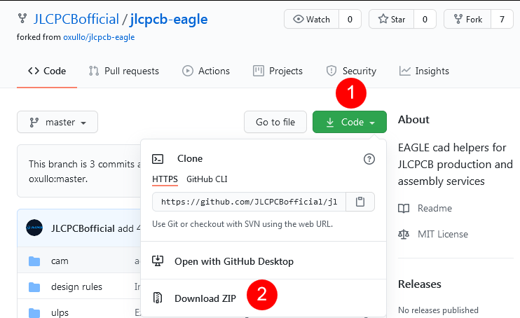
Download the ULP from the JLCPCB official repository
Step 2: Install the ULP
Copy jlcpcb_smta_exporter.ulp into EAGLE's ulps folder so EAGLE can find it:
- Windows: C:\Users\<username>\Documents\EAGLE\ulps
- Linux: /home/<username>/EAGLE/ulps
Select jlcpcb_smta_exporter.ulp and open it.
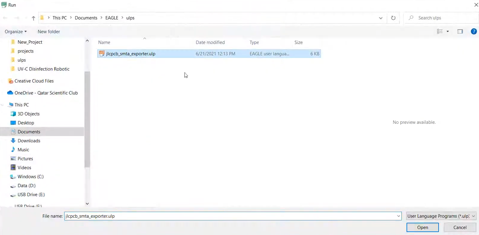
Selecting jlcpcb_smta_exporter.ulp from the ulps folder.
Step 3: Run the ULP from the board editor
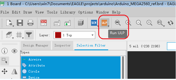
Open your project's Board (.brd) editor. The Run ULP button is on the top toolbar (the ULP icon).

The ULP / Run ULP button location on the EAGLE board-editor toolbar.
Click the Run ULP button.
Click the Run ULP button in the board editor.
Step 4: Exporting BOM and CPL files from EAGLE
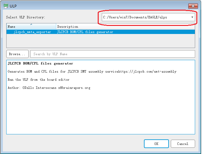
The JLCPCB BOM/CPL files generator selected
EAGLE shows the exporter JLCPCB BOM/CPL files generator.
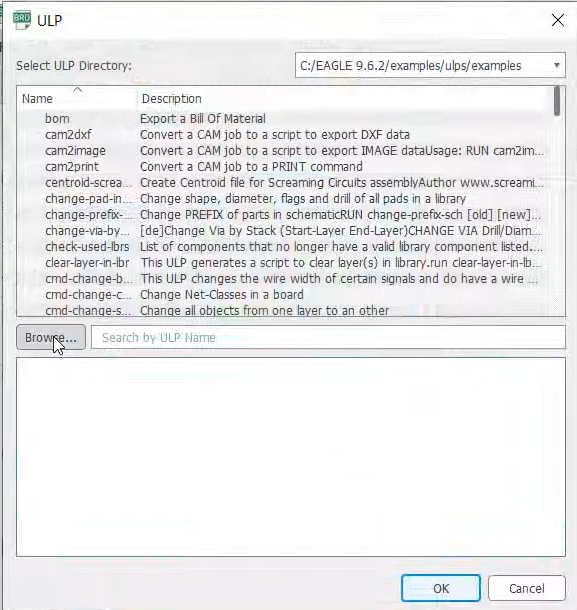
Browse to your EAGLE/ulps directory in the ULP dialog.
Click OK to run it. In the ULP dialog, click Browse and go to your Documents\EAGLE\ulps folder (by default EAGLE shows its own examples folder).
Step 5: Choose the export layer
Pick the side to export Top or Bottom depending on where your SMT parts are, then click OK. Run the ULP once per populated side.
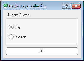
Select the export layer (Top or Bottom).
Step 6: Files exported
The ULP confirms where it saved the files and creates <board>_<side>_bom.csv and <board>_<side>_cpl.csv.
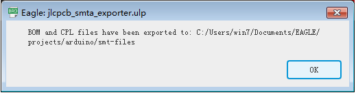
Confirmation dialog showing where the BOM and CPL were exported.
The exported BOM
Open the generated BOM. The columns has Comment, Designator, Footprint, LCSC Part # already match JLCPCB's sample, so no reformatting is needed. Any LCSC_PART attributes you added appear in the last column.
The BOM produced by the ULP
Add LCSC part numbers to your components
So JLCPCB can match each part automatically, giving every component an attribute named LCSC_PART set to its LCSC part number. In the Schematic Editor, select a part, open Attributes, add LCSC_PART, and paste the number.
The ULP copies this value straight into the BOM's LCSC Part # column. To look up a part's C-number, use the JLCPCB Parts Library and search by part or keyword:
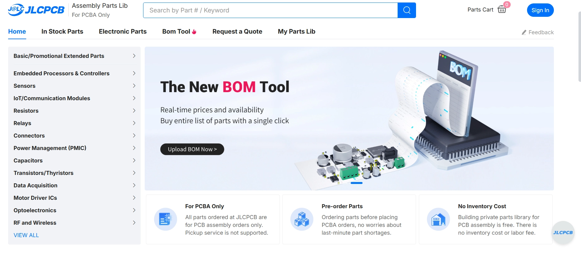
JLCPCB Assembly Parts Library
Note
Parts left without an LCSC_PART value can still be matched later on the JLCPCB website, but filling them in now saves time at upload.
Step 7: Upload the BOM and CPL to JLCPCB
On the JLCPCB SMT Assembly order page, after PCB, go to Upload BOM/CPL. Upload the BOM.csv to the BOM slot and the CPL.csv(position) to the CPL slot.
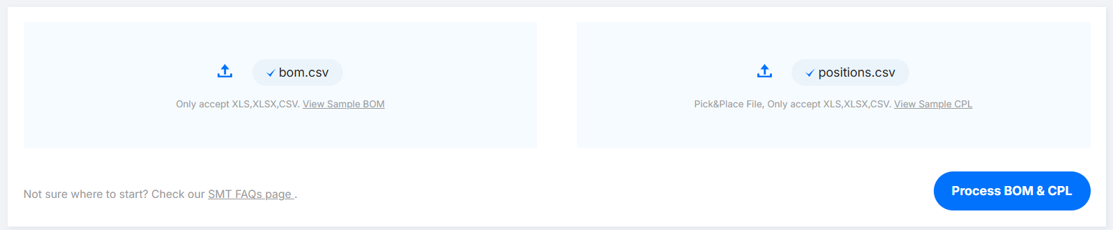
Uploading the BOM and CPL files on the JLCPCB SMT Assembly page.
Step 8: Review and select parts
JLCPCB matches your components to its library and shows the matched part, stock and price for each line. For any part that needs attention (often one without an LCSC_PART), click the row and choose a suitable part from stock, then continue to Quote.
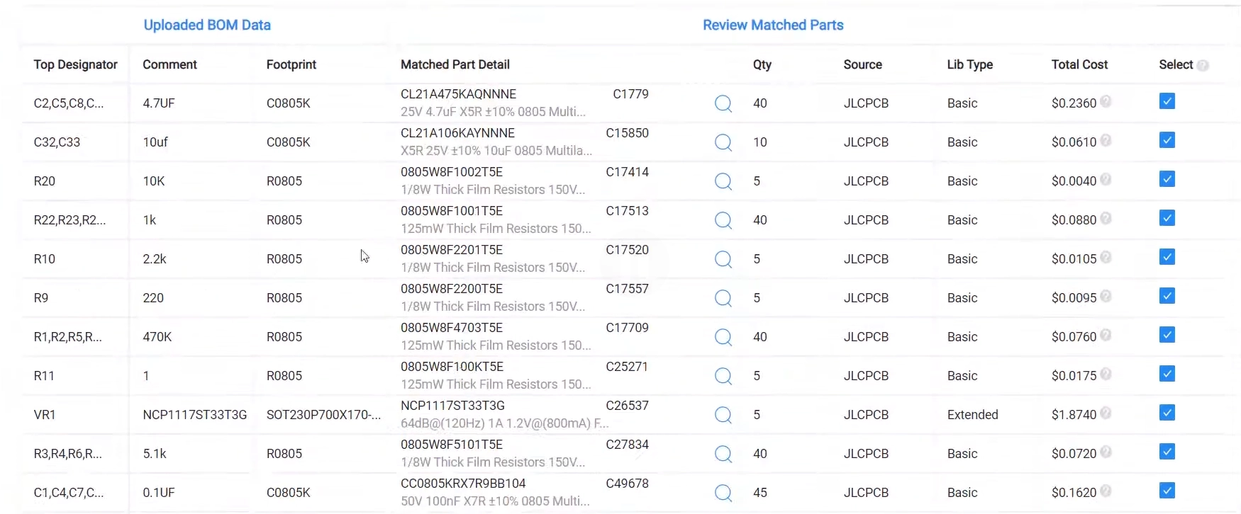
Reviewing and selecting the matched components on the JLCPCB website.
With JLCPCB's jlcpcb_smta_exporter ULP, generating assembly files from EAGLE is a one-click job: install the ULP, add your LCSC_PART numbers, run it for each populated side, and upload the resulting BOM and CPL straight to your JLCPCB SMT order.