How to Generate Gerber and Drill Files in PCB Wizard
Last updated on Apr 24, 2025
PCB Wizard is an easy-to-use package for designing single-sided and double-sided printed circuit boards (PCBs) from New Wave Concepts Limited.
Generate Gerbers
To produce Gerber files, select Tools → CAD/CAM → Export Gerber from the menu bar.

Figure 1. Export Gerber menu item
A window will appear that allows you to specify some options.
- Check RS-274X(extended)
- Select all layers.
- Check Place each exported layer in a separate output file
- Include aperture table within output file will be automatically checked if RS-274X is used.
- Check Fill pad drill holes
Now click OK, some Gerber files and the drill file will be generated in the project folder.

Figure 2. Gerber options
Let’s have a look at the generated files:

Figure 3. Generated files
With these file names, we can’t be told what’s the function of each file. Even though we can see the function of each file in Figure 2, but when we pass the files to a PCB fab house, this important information will be lost. JLCPCB prefers Protel naming conversions, so let's change the filename extensions according to Figure 2.
Note By default, filename extensions are hidden in Windows, for how to show them, just google "show filename extensions windows".
- Rename .gb0 to .GKO (board outline)
- Rename .gb1 to .GBL (bottom copper layer)
- Rename .gb2 to .GTL (top copper layer)
- Rename .gb3 to .GTO (top silkscreen)
Now the folder looks like this:

Figure 4. Filename extensions changed
If we look at these files, we can see the files for soldermask are missing, let's generate them.
Generate Soldermask
Again, select Tools → CAD/CAM → Export Gerber. The window for options will appear, this time just check one more option than the first time:
- Check Plot pads only (this will only generate the top and bottom soldermask instead of the copper patterns)
Click OK button to generate the files.

Figure 5. Check Plot pads only
We now have the following files in the project folder.

Figure 6. Soldermask files
- Rename .gb1 to .GBS (bottom soldermask)
- Rename .gb2 to .GTS (top soldermask)
- Delete .gb0 and .gb3
These are the files we get at the end:

Figure 7. Gerber files with Protel filename extensions
Fix the drill file
If we open the .drl file with a text editor (Excellon files are plain text files), we can see something like this:

Figure 8. The raw drill file
The problem of this file is that the tooling information between M48 and % sign is not included. In fact the tooling information (the size of all used drill bits) is a .inf file.

Figure 9. The report file (.inf) contains the tooling information
We can just add this tooling information into the drill file manually (please note the Tnn lines after M48 in the screenshot below). The syntax is simple:
- nn in Tnn are tooling numbers.
- After Tnn is a letter C.
- After letter C, is the size of this tool.
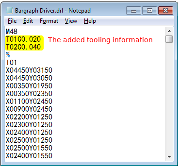
Figure 10. The fixed drill file
Verify the files
Before uploading your Gerbers and drill file to JLCPCB for production, it’s highly recommended to cross-check the generated files with a 3rd-party Gerber viewer.
If you find any issues, fix them and export the Gerber/Drill files and check them in the Gerber viewer again.
There are some nice Gerber viewers here and there, just use the one you feel handy.
- Gerbv
- tracespace view
- Reference gerber viewer from ucamco

Figure 11. Inspect the files in Gerbv
If everything is OK, now you can move the production files into a folder (include the .inf file), zip it, upload it to JLCPCB to place the order.

Figure 12. Preview of the board in JLCPCB.com after uploading