
How to generate BOM and Pick and Place File in Sprint-Layout 6
Last updated on Apr 24, 2025
In this tutorial, let's see how to generate BOM (Bill of Materials) and CPL (Component Placement List)[Also known as a Centroid file, Pick and Place File, XY File, etc.] for JLCPCB SMT and hand soldering service in Sprint Layout 6.
A very simple PCB that contains only 4 components is used for this tutorial, but the idea is the same for boards have many components.
Set properties for components
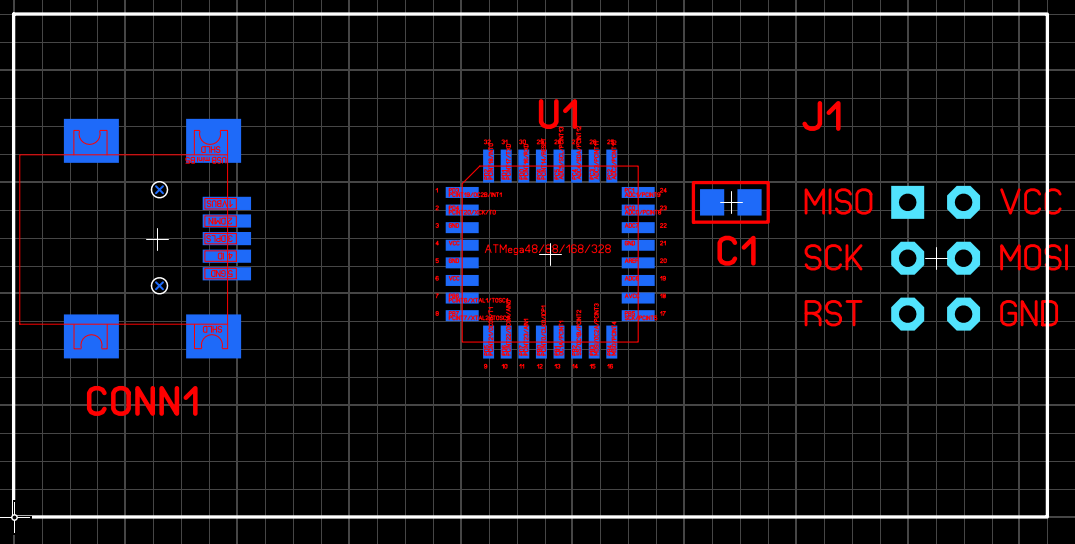
Figure 1. The sample file used for this article
Before generating the BOM and CPL files, we need to add some meta data for components, this information will be used in BOM and CPL files.
For example, in the following screenshot, we set ID, Value, Comment and Package for the microcontroller ATmega328P-AU.
Pay attention to the value for Comment, we use this field for a special purpose: Every part available for assembly at JLCPCB has a unique "LCSC Part #", its format is Cxxxx, please visit JLCPCB Part Library to find the parts. If the BOM has this "LCSC Part #", this part will be 100% hit when the system executes the BOM matching operation.
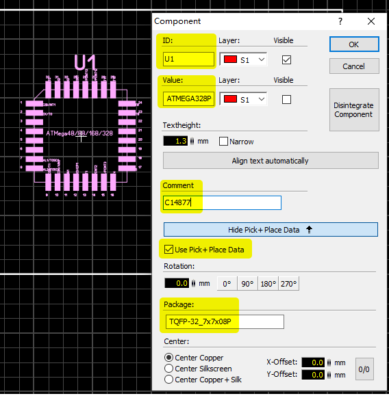
Figure 2. Component's properties

Figure 3. LCSC Part # of the part (also called JLCPCB Part #)
Set meta data for every component.
Export the raw data
To export the data, first we need to make the Components Panel visible, just select Options → Components-Panel.
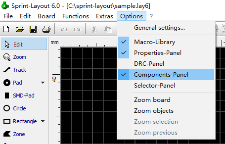
Figure 4. Make Components Panel Visible
Now, click the Export button on the Components Panel.
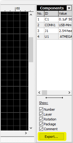
Figure 5. The Export button
The Component-Data Export window appears. Check the options as per the screenshot below.
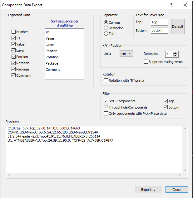
Figure 6. The Component-Data Export window
Click the Export button, Sprint-Layout will ask you to specify the filename and file type. Select All files for Save as type, in this way we can use CSV as the filename extension.
| Note | The reason we use CSV as the filename extension is because if a spreadsheet program is installed, the CSV will be opened automatically in some Operating Systems. |
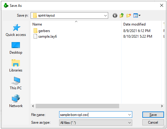
Figure 7. Save the file
Edit the raw data to a CPL file
Make two copies of file sample-bom-cpl.csv and rename them to sample-bom.csv and sample-cpl.csv.
Double click sample-cpl.csv, LibreOffice will bring up the following dialog. Click OK.

Figure 8. Import CPL
Now, CPL has been imported.

Figure 9. CPL in LibreOffice Calc
Delete the not needed lines and modify the file accoring to JLCPCB’s CPL specification.
Now we get the clean file.

Figure 10. CPL file is done
Click Ctrl+S to save the file, keep using text CSV format.

Figure 11. Save CPL file
Edit the raw data to a BOM file
Double click sample-bom.csv, LibreOffice will bring up the following dialog. Scroll to Package column and select Text as the Column type to keep the leading 0s for 0603, 0402, etc.

Figure 12. Import BOM
Click OK.
Edit the import file to a clean BOM according to JLCPCB’s BOM specification. Like this:

Figure 13. BOM file is done
Click Ctrl+S to save the file, keep using text CSV format.

Figure 14. Save BOM
The rotation problem
After uploading Gerbers, BOM and Pick and Place files, if everything goes well, you’ll see a preview window which has a rendered PCB with components on it.

Figure 15. Preview
In the above screenshot you can see the orientation of U1 (ATmega328P) is wrong: The correct pin 1 should be the topmost pin on the left side. We check the Rotation value in the CPL file and found the current value is 180 degree, if we rotate it 90 deg more we’ll get the right rotation. Now, change the rotation in the CPL to 270 deg and upload it again, the orientation has been fixed in the new image (This is a workaround though, JLCPCB will solve this problem in the near future)

Figure 16. The rotation of U1 has been fixed
Sometimes you may see other issues in this review page: for example, parts are not correctly aligned with the footprint, this is because the preview system is still not good enough. You may ignore this when you place the order, all files will be reviewed by engineers, they’ll correct the position and make a high-resolution DFM image for you to confirm.