How to export CircuitMaker 2 PCB to Gerber and drill files
Last updated on Apr 24, 2025
Gerber and NC Drill setup
First, we need to configure some options. Once the settings are configured, CircuitMaker will remember the settings for a specific project, which means you don’t need to set these options every time before you generate the files.
Right click on the project name (the .PrjPcb file) on the Projects panel, a pop-up menu will appear, click Generate Outputs.

Figure 1. Generate Outputs menu item
Some Outputer are listed in the Generate output files dialog, click Configure for Gerber Files.

Figure 2. Configure Gerber options
A window will appear that allows you to specify some options.
General tab

Figure 3. General tab setting
Layers tab
Select necessary layers, for example, for a 2-layer design, you need to select the following layers:
- Top Overlay
- Top Paste
- Top Solder
- Top Layer
- Bottom Layer
- Bottom Solder
- Bottom Paste
- Bottom Overlay
- Outline (Note that different Mechanical layer can be used for outline, in this example, it’s M2)
If it’s a 4-layer or 6-layer design, don’t forget to select the inner layers.
Warning:Please don’t check Keep-Out Layer (it will be exported to a .GKO file), our system looks for .GKO and may grab it as the outline. The Keep-Out Layer is used to put objects that blocks or prevents the placement of copper objects within an area.

Figure 4. Layers tab setting
To have a cutout (remove all material), just draw the shape on outline layer.
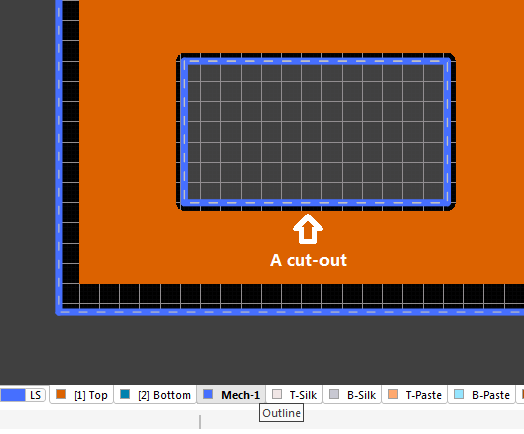
Figure 5. A cut-out
Drill Drawing tab
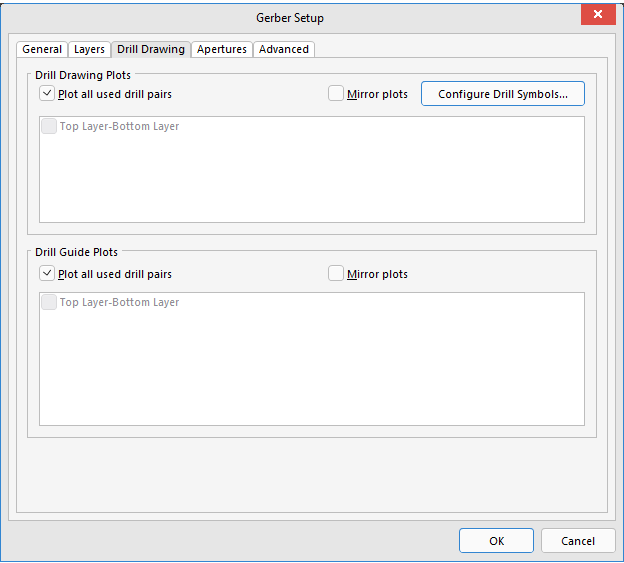
Figure 6. Drill Drawing tab setting
Apertures tab
Check Embedded apertures (RS274X)

Figure 7. Apertures tab setting
Advanced tab

Figure 8. Advanced tab setting
Click OK button to finish the Gerber Setup.
NC Drill Setup
Click on Configure on the right side of NC Drill Files.
- Use 2:4 for format
- Check Suppress leading zeroes
- Check Reference to absolute origin
- Check Generate separate NC Drill files for plated & non-plated holes
- Check Use drilled slot command (G85)

Figure 9. NC Drill Setup
Generating files
Check both Gerber Files and NC Drill Files, click Generate button.

Figure 10. Check Gerber and Drill then Generate
CircuitMaker will say "The project has modifications…", just click Save and Commit changes.

Figure 11. Save and Commit changes
Then click OK in the Save to Server dialog.

Figure 12. Save to Server
Click the Release button, this will save the generated files to cloud.

Figure 13. Release
A window called Confirm Release will appear, you can write a release note if you want, then click OK.

Figure 14. Confirm Release
A new windows will say "Project has been released successfully, open in Web Browser."

Figure 15. Released
Click on open in Web Browser, this will open the released files in a web browser. Click Hide Files to show the file, then click the download icon to download the Gerber and drill files.

Figure 16. Released files in web browser
Verify the files
Before uploading your Gerbers and drill file to JLCPCB for production, it’s highly recommended to cross-check the generated files with a 3rd-party Gerber viewer.
If you find any issues, fix them and export the Gerber/Drill files and check them in the Gerber viewer again.
There are some nice Gerber viewers here and there, just use the one you feel handy.
- Gerbv
- tracespace view
- Reference gerber viewer from ucamco

Figure 17. Inspect layers in Gerbv
If everything is OK, now you can upload the zip to JLCPCB to place the order.

Figure 18. Preview of the board in JLCPCB.com after uploading