How to Generate Gerber and Drill Files in Proteus
How to Generate Gerber and Drill Files in Proteus
When you finished your design in Proteus, the last step before sending it off to the fab house is to generate the Gerber and Drill files. PCB fab houses will use these Gerber and Drill files to make your boards. Some special requirements for JLCPCB are also covered.
Generating the Files
Execute Output → Gerber/Excellon Output… in the Menu bar.

Figure 1. Output Gerber/Excellon Menu Item
The CADCAM Output window will appear and you need to do some configurations:
- Choose "Output to a single ZIP file?"
- Select the necessary layers (Tick "Inner x" when copper layers > 2)
- Ensure that "Edge (will appear on all layers)" is not selected.
- Tick "Mech 1" layer
- Choose "Mech 1" for "Slotting/Routing Layer"
- Choose RS274X as the Gerber Format. Gerber X2 is not supported.
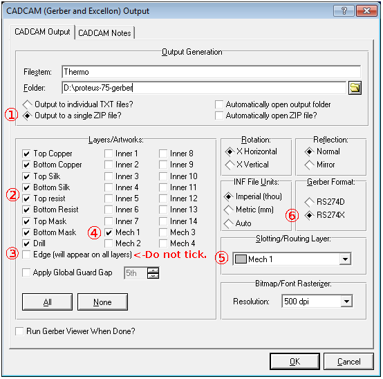
Figure 2. Proteus 7.5 Gerber Options

Figure 3. Proteus 8.9 Gerber Options
Click the OK button on the bottom right of the window. The Gerbers and the drill file will be generated and saved into a single ZIP archive.
Some Comments
Edge (will appear on all layers) Option
Don’t tick this option.
And here’s the considerations behind:
JLCPCB prefers a separate layer for board outline. With a single file for outline, it’s easier for computer programs to process the outline file and it also tells CAM engineers how to mill the boards.
If this "Edge" option is ticked, elements on Edge layer will appear on every Gerber layer (well this is kinda OK).
But when you have inner cutouts and draw them on Edge layer, these elements for cutouts will also be output onto every Gerber layer, this will mess Gerbers up.
So if we use Mech 1 for board outline and cutouts and Slotting/Routing, we can get a single file for outline.
Board Outline
Please draw a continuous watertight board outline on Mech 1 layer (generally with 10 mil width lines). This outline layer should only contain the board outline, no dimension measurements and text and other stuff.
If the outline was placed on Board Edge layer, it can be switched easily: Right click the outline then Change Layer → Mech 1
Figure 4. Change Outline Layer
Inner Cutouts
Inner cutouts (non-plated) and other kinds of contour that needs to be cut should be drawn on Mech 1 layer. Just draw the edge of the area that needs to be removed.
Non-plated Slots
Draw them on Mech 1 layer.

Figure 5. Non-plated Slots Minimum Width
Plated Slotted Holes
These slotted holes are used for DC barrel power jack/connectors, audio connectors and some micro USB connectors, they have wide and thin pins.
The minimum plated slot width is 0.65mm (25.6 mil), which is drawn with top and bottom copper pads, as illustrated in the figure below.

Figure 6. Slotted Holes Minimum Width
| Important | Just to be safe, you can write a special instruction in the remark area in our ordering system when you place the order, write like: "Please note: there are 3 plated slotted holes in this design". Our CAM engineer will sort them out from the "context" (like the annular ring and solder mask opening) when processing the files. |
Inspect the Files in a Gerber Viewer
Before uploading your Gerber files to our website for production, it’s highly recommended to cross-check the generated files with a 3rd-party Gerber Viewer.
When you are checking the file, please pay attention to the following items.
- Does the board outline exist?
- Is the board outline watertight(continuous/no gaps)?
- Do all inner cutouts and unplated slots show in the filename - CADCAM Mechanical 1.GBR or filename - CADCAM Mechanical 1.TXT?
- Do all drilling holes shown and are aligned with other layers correctly?
- Are vias covered by mask or exposed as per your design?
- And the Silkscreen, do they look good?
If you find any issues, fix them and export the Gerber/Drill Files and check them in the Gerber viewer again.
There are some nice Gerber viewers here and there, just use the one you feel handy.
- Gerbv
- tracespace view
- Reference gerber viewer from ucamco

Figure 7. View the Files in Gerbv
Last updated on Jan 2, 2024